Blackhawk 29 aka 2nd Stage Sustainer Build "and More"

The Rocketry Forum

Help Support The Rocketry Forum:

This site may earn a commission from merchant affiliate links, including eBay, Amazon, and others.

dixontj93060

Well-Known Member
Joined
Feb 19, 2009
Messages
13,083
Reaction score
45
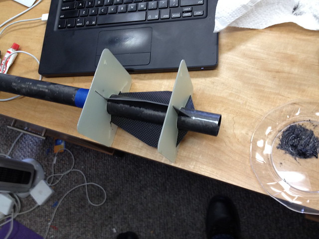
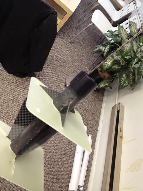
Well after viewing Dan Patell's nice two-stage Formula 54 build it got me back to a project I have had on the "back burner" for some time. I purchased a Blackhawk 29 from Wildman when they first came out. I didn't so much purchase it as a stand alone rocket, but really I thought it would be a sweet sustainer in a two-stage build, not unlike a Loki Dart. And then seeing the Formula 54 fin profile, I thought it would look nice as the booster. So now officially resurrected I pulled the Blackhawk 29 out of the build pile and am assembling extra parts for my bins to do the booster.

Blackhawk29+38mm2stage_v3.jpg
 
Last edited:
As with most of my build threads this one will be slow and sporadic with no set time limit for this project.

First order of business was measuring and cutting the main body tube. I did so with my Dremel cut off wheel leaving a lonely main parachute bay.

6472373863_87cee59f06_z.jpg


Then on to the aft end. Marked fin positions and mixed some JB Weld (for tacking, the Cotronics as in the instructions will be used for the fillets). Note the dark color of the JB Weld. I didn't want the grey/black contrast so I filled/tinted the JB Weld with some lamp black from my EX stash to get it back to a nice black color (caution for those that haven't used lamp black--it can wreck havoc on your clothes and other materials as, if not careful, it gets everywhere).

6472195811_48433a01e9_z.jpg
 
Then using the same mix of JB Weld I sanded/added the Slimline retainer. When I do the fillets for the fins I will give the top retainer edge a nice sloping fillet also. This retainer and its future modifications will be a critical component in doing the inter-stage coupling.

6472195827_9bdd56aa0c_z.jpg


Then with the last of the JB Weld I went ahead and added a body tube section for the sustainer av-bay (which should look familiar ;)).

6472195841_1c52363435_z.jpg


After this I set everything in my office bathroom with the space heater on to aid in curing.
 
Outstanding!

Good luck finding it. Really good luck, this thing is gonna scream. That's a great idea for an Av-bay.

What ya going to use for electronics & staging?
 
Good luck finding it. Really good luck, this thing is gonna scream. That's a great idea for an Av-bay.

Yep, as they say--the thrill of the chase. I'll do what I can to make it work--drogueless and then fairly small chute; BRB tracker in nose.

Outstanding!
What ya going to use for electronics & staging?

Raven 250g variety in sustainer and since it is minimum diameter and I don't want to mess with the Jim Jarvis ribbon cables, I will have a second standard Raven in the interstage coupler for ignition and booster deploy.
 
JB Weld cured nicely in just three hours in my makeshift oven. Critical fillets tomorrow.

6473277869_fff050bacd_z.jpg
 
What are your plans for the slimline? I have one on my miriah38, and am debating on how I want to streamline it some. :confused2:

:pop:
 
What are your plans for the slimline? I have one on my miriah38, and am debating on how I want to streamline it some. :confused2:

:pop:

If you are speaking of the finishing aspect, it will be similar to these two minimum diameter builds--nothing special really, just an epoxy fillet to smooth the right angle edge on the forward face of the retainer. If you are speaking about the secondary modifications to aid in the attachment to the interstage coupler, I have two options I am considering at this point (as a qualifier, I don't want to affect the flight of the sustainer by adding posts/sleeves to the minimum diameter design)... One option for positive alignment are slots on the bottom of the Slimline and have them seat over brass stock at the bottom of the transition socket. The second option is to drill and tap into the fore area of the Slimline above the aft body tube edge and use shear pins all around, again as a means of more positive retention in the transition socket. Both options are being considered and they are actually not mutually exclusive, i.e., I may use both depending on the stability of the final assembly.
 
Did an inventory at home last night and found out I didn't have all the scrap parts that I thought so had to place a couple of orders with PML and Wildman today. Getting ready to start on sustainer fillets, but first took some time to cut booster parts including the airframe, the interstage coupler, motor mount and fins. I could have just used my Formula 54 fins as a template, but didn't think of it before printing out from Rocksim. These are not Formula 54 fins though as they are 0.125" G10. Fin thickness doesn't affect performance much--in fact, in this application adding weight optimizes the design so the heavier fins make up for the larger cross-section.

6478214643_cbe6f473b8_z.jpg
 
Moving on to the Blackhawk fillets. According to CJ and the instructions these are critical to get right so trying to do it "just so." I decided that it would be better for me to do one set at a time versus the whole bunch. Although the mix may be pretty thick I didn't want to risk it, so I divided up the hardener in three even lots (well I did leave a bit over in a fourth for the Slimline retainer) of 1.1 grams each. Thought I'd better do this to save myself from running out on the last fillet set.

6478468911_ff0da27f11_z.jpg


So two set aside and one mixed with 5.5X the black resin. As Jed Clampett would say, "black gold, texas tea" at least that's about the consistency; a tar ball washed up on the Louisiana shoreline.

6478468373_827c20f93b_z.jpg


Then carefully applied and along tape edges and smoothed with dowel. Tape removed after about 5 minutes and first set shown below. Will wait about a half hour to set and then it goes into the "oven."

6478467903_3d8e9bcac4_z.jpg
 
This is a COOL thread!

I have three rockets to build in the near future. After that, I want to build a two-stage rocket.

I'm looking forward to learning from this thread. :cheers:
 
This is a COOL thread!

TZ250, thanks.

I'm now working through fillets on sustainer... In between I have been doing some measurements on parts and laying out the interstage coupler. After doing more simulations I realize I need dual deploy and tracking on the booster as well as the sustainer (booster altitude will be 7000+ feet) thus the interstage coupler has become more complex than originally envisioned. This is OK, I like a challenge. Current view is to have the transition and a 3" section of booster airframe act a nosecone and have a small chute deployed at booster apogee (I simulated the booster separately and it is stable in many motor configurations so a high probability of returning ballistic, thus the apogee chute). A 30" hemispherical chute located aft of the interstage coupler will be deployed upon decent at 800 feet. Some layered pics of the layout are attached. BTW, much inspiration taken from Adrian A.'s pre-L3 design.

BH292STGCOUPLER1.jpg

BH292STGCOUPLER2.jpg
 
Last edited:
I am watching this thread pretty closely as well. I am finished with the sustainer of my 2-stage Formula 54, and will be turning my focus to the electronics soon. I am intrigued by how you are planning yours, and mine may mirror your design to some extent.

My main question is regarding the fit of the Slimline into the transition. It seems like a limited length of engagement with a long moment arm on either side of it. To me, that makes it a potential pivot point should you get any radial loading of the sustainer (i.e. coning). Does this concern you at all?
 
My main question is regarding the fit of the Slimline into the transition. It seems like a limited length of engagement with a long moment arm on either side of it. To me, that makes it a potential pivot point should you get any radial loading of the sustainer (i.e. coning). Does this concern you at all?

Yes it does, ALOT. In fact, although the length is one caliber (similar to a coupler), I don't know if it will work. Besides making the socket a fairly tight fit (I will core out the transition and line with Kevlar mat), it will have shear pins around the transition and each pin will be sunk into the fore end of the Slimline retainer. If this doesn't give it enough stability I then plan to put four equi-distant notches in the bottom of the Slimline and then have pins at the bottom of the socket where the aft end of the Slimline will seat and secure it from angular movement. The final step, if needed, would be to put "stabilizer plates" extending from the top of the transition partially up and between the sustainer fins. In the end, it is an experiment. If it isn't stable enough I won't fly it and I will have to go back to the drawing board.

BTW, if I wasn't trying to get the overall look of the booster/transition like a Loki Dart and minimum diameter flight, I would likely be doing the coupling different and much more like my other HPR two-stager.
 
Last edited:
OK, fillets now complete including beveled fore edge on Slimline retainer. They came out fairly well.

6483018979_7ed5c9facd_z.jpg


And then did the beveled edges on the booster fins. Although I'll be doing fiberglassing of booster components this weekend, I'm about as far as I can go without getting my PML and Wildman orders in hand.

6483018265_0cec46b64f_z.jpg
 
Again, waiting on parts, but have made some progress today. First, as mentioned above, laminating the booster airframe.

6495842253_8a569912dc_z.jpg


And also laminating the inside of the interstage coupler to reinforce.

6495827173_54e3c72ea3_z.jpg
 
More importantly, and more challenging--the av-bay for the sustainer. First snapshot is the top of the av-bay sled utilizing a Raven2. In the middle/top is a 2-pole power switch (turned upside down) and toward the middle/bottom is a two-position common switched positive terminal block to simplify e-match connection.

6495786423_ff8a6d46a2_z.jpg


A side view of the board gives you an idea of the small locking pushbutton which is routed through the board and will be activated via the sampling hole in the back side of the coupler band.

6495799889_b3125ca364_z.jpg


Looking now into the aft end of the av-bay (aka, Rousetech 29/40-120 spent/cracked casing). Not shown, but there is room on top for another #8 all-thread piece which will be routed into each av-bay bulkhead to balance the applied force.

6495809811_f75df6274c_z.jpg


And then for completeness a look into the fore end of the av-bay seeing the end of the Raven. You might notice I used a fairly thick piece of G10 for the board (1/8"); I did so just because it gave the right spacing needed top/bottom for the components and switch access.

6495818725_e0fc2d2e76_z.jpg
 
Last edited:
My main question is regarding the fit of the Slimline into the transition. It seems like a limited length of engagement with a long moment arm on either side of it. To me, that makes it a potential pivot point should you get any radial loading of the sustainer (i.e. coning). Does this concern you at all?

OK, Dan, as you pointed out, critical juncture here... I did some careful sanding with my Dremel and a sanding block. Not completely done yet as I need some space to put in the Kevlar mat internal to the socket, but so far I'm encouraged. I am holding the whole sustainer out vertically and only holding the urethane transition at the aft edge--very nice fit with no movement yet the Slimline slides out fairly easily.

6521884869_90aa4ee2ab_z.jpg


Surprisingly, as it wasn't really planned, the epoxy fillet at the top of the Slimline doesn't look too bad and does a fairly nice job of matching the transition angle.

6521897515_7d0d636875_z.jpg
 
Very nice work. The slimline on a minimum diameter rocket was bothering me at first but with the epoxy it looks great. A natural fit with the transition cone.
 
OK, Dan, as you pointed out, critical juncture here... I did some careful sanding with my Dremel and a sanding block. Not completely done yet as I need some space to put in the Kevlar mat internal to the socket, but so far I'm encouraged. I am holding the whole sustainer out vertically and only holding the urethane transition at the aft edge--very nice fit with no movement yet the Slimline slides out fairly easily.

Looks nice! I still don't know what to suggest on this interstage coupler. A part of me is skeptical, especially with larger motors. Only way to find out is by trying it.
 
Very nice work. The slimline on a minimum diameter rocket was bothering me at first but with the epoxy it looks great. A natural fit with the transition cone.

I agree with this as well. No intention of ridiculing Tim, but I get the heebie jeebies when I see these retainers on MD rockets. For example:

page3-1038-full.jpg


Yuck.

I would personally rather deal with friction fitting or retaining off the top of the motor in these circumstances.
 
I like the clean lines of a friction fit, but this above example is kinda cool also. That cone at the bottom reminds me of a hypersonic rocket with conical aerodynamic stabilization. So at mach 5 when the fins burn off you can still rely on that retainer...
 
Dan, c'mon man, mine isn't nearly that bad!

Not even close...just posted that as a warning to everyone!

I like this project a lot and I am intrigued to see how it comes out. I am tardy on posting information on my 2 stager, mainly because not much as been done on it. So I am currently living vicariously through this thread.
 
OK, so where do the parts shown in post #18 (plus a few in my scrap box) go? Well first, the two centering rings round out my needs for the booster motor mount (dry fit shown below with one fin shown as reference):

6522363183_e3e182d79b_z.jpg


Most of the others work together to make the sketch of the interstage coupler shown in post #12 a reality. After a bit of cutting, fitting and sanding we have, from 12 noon clockwise: the aft coupler plate and bulkplate, the booster cap body, center FG charge sleeve, the dowel plunger (which turned out to be a coupler plate), aft transition attach (better to use ply than G10 as in drawing), the mid plate (which has transitioned to two G10 plates sandwiched together--the top will will become a CR for the charge sleeve), and finally the interstage coupler itself. Obviously more later as I put this stuff altogether...

6522363631_4fc2445780_z.jpg
 
So a bit done here on the booster. First assembling the motor mount leaving spacing for the Aeropack retainer and mid-CR set up for fin root edge.

6534229755_7cb361c131_z.jpg


And then gluing some parts together here... From 12 o'clock the booster cap and plunger, the inside of the interstage coupler socket where the sustainer fits and then the booster cap charge sleeve and mid bulkhead.

6534212657_0c6056e757_z.jpg
 
Booster fins tacked in.

6539007539_991a4e7a31_z.jpg


Internal fillets, then tip-to-tip glass on the fins across motor mount (Overkill for Mach 1.25?; well some would say yes, but my suspect of G10 and its propensity to microfracture leading to hidden failure modes has been well documented on this forum).

6539008309_3ebbab64a4_z.jpg
 
Last edited:
Back
Top