Wayco's RW Mongoose 54 build

The Rocketry Forum

Help Support The Rocketry Forum:

This site may earn a commission from merchant affiliate links, including eBay, Amazon, and others.
Wayne, any updates to your build?

I've kept him busy for the last couple of weeks, but have released him from "other duties" so he can get back to the Mongoose 54 build. There should be a post today since I know he has been working on the avbay.
 
I have made some progress with this build, but it's been in fits and starts. I did a "frenzy" finish to the fillets, and didn't take any more pictures. Now I'm working on putting an RRC3 and SLCF into the avbay. I was gonna wait to post it all up after it's done, but I'm pretty close now, and will catch you all up on it.
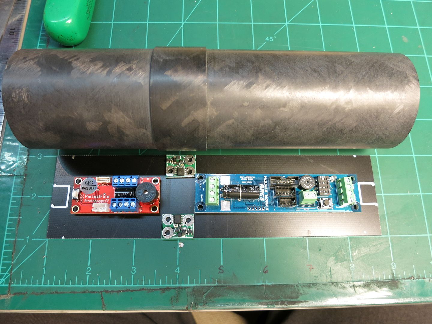
First, I laid out the parts on the sled that came with the kit:
016_1.jpg

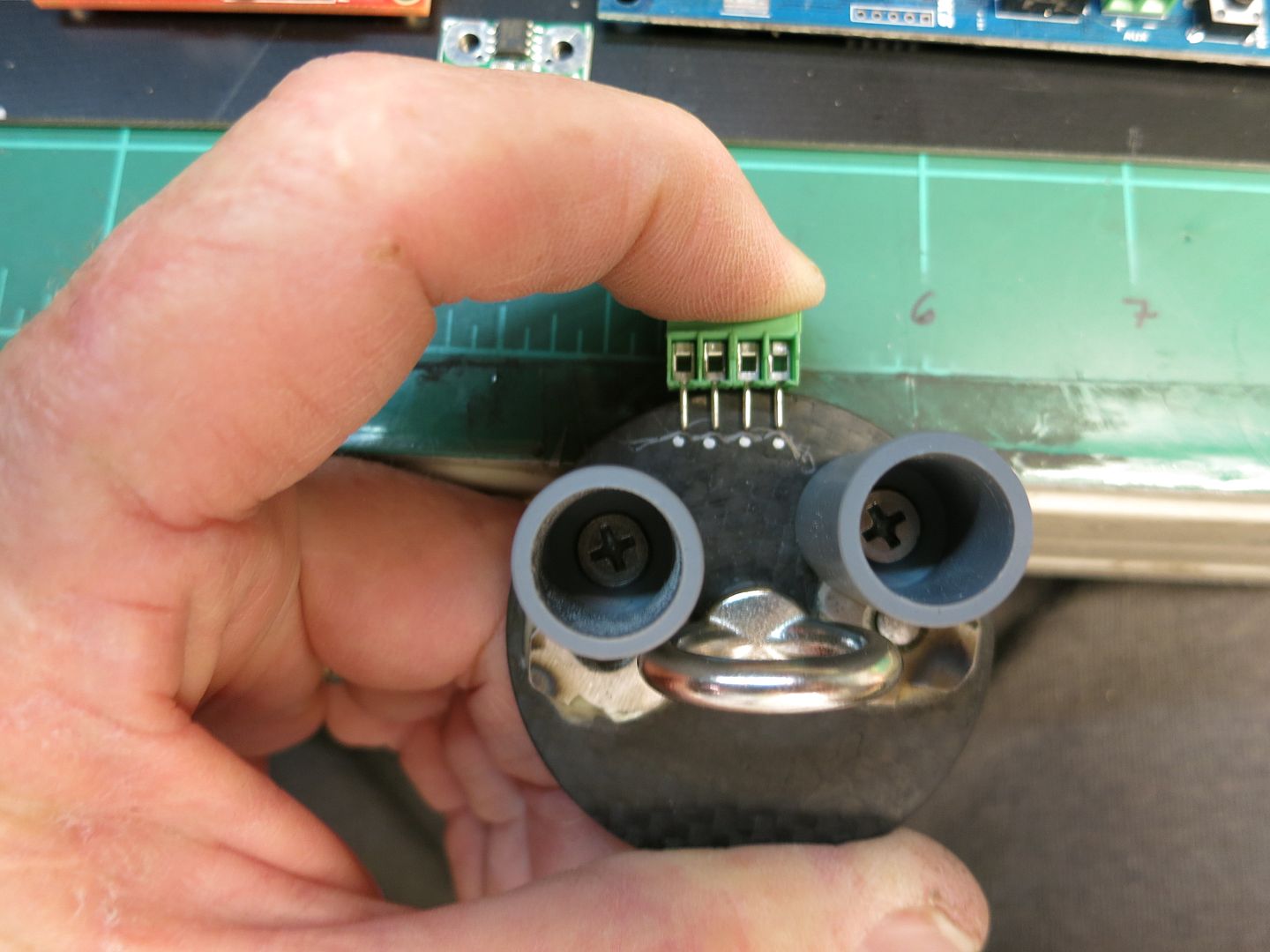
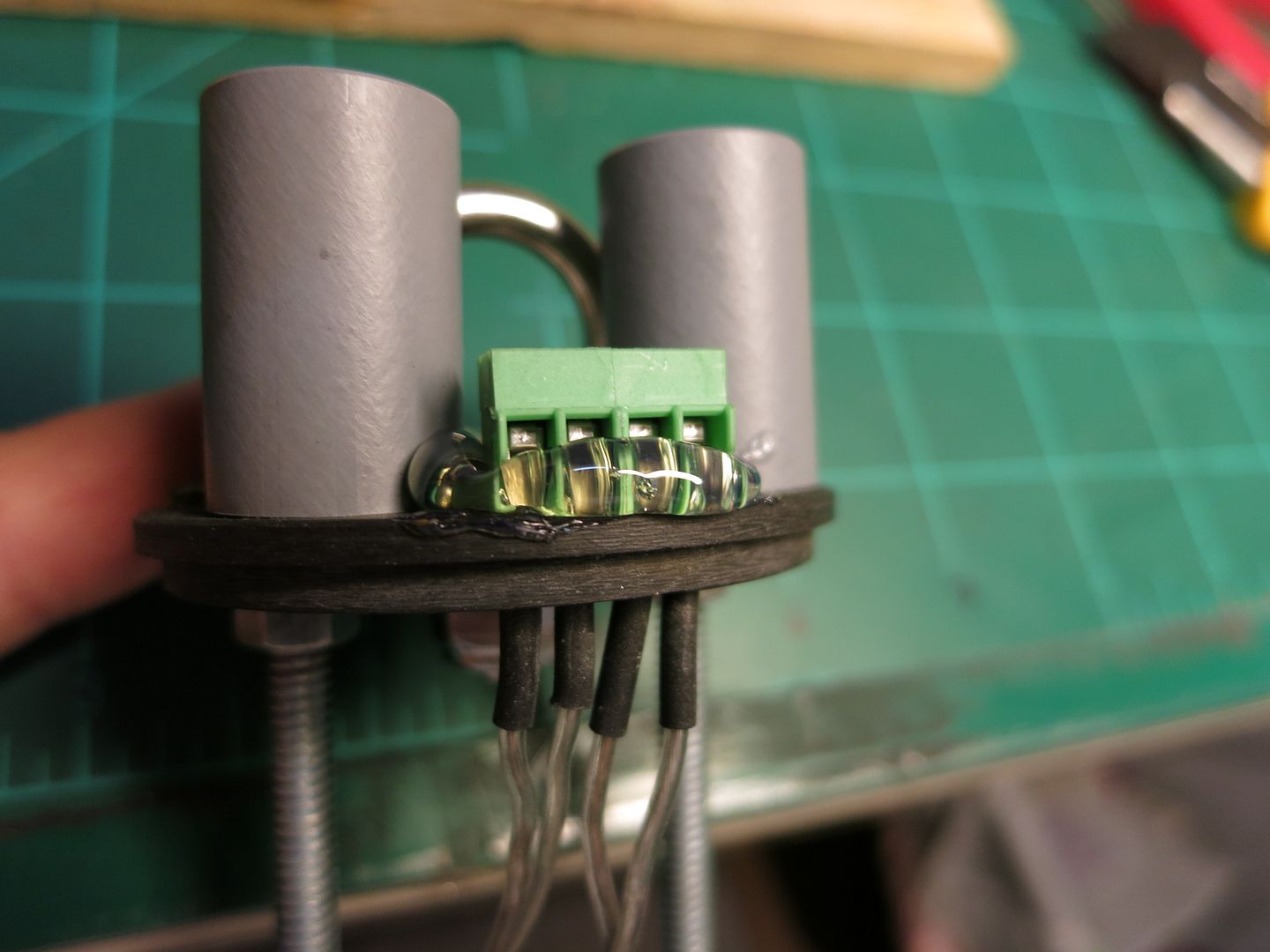
Silver marks are for where the nuts fit inside the lids. I also laid out parts on the lids. Since carbon fiber is conductive, I had to insulate the pins on my terminal blocks with heat shrink. Larger holes were drilled to accomodate this. I also mounted the "Dog House" charge cups by drilling and threading the holes in the bulkplate, and cutting off excess threads on the inside to make it easier to fit everything in. The all thread is mounted on the upper bulkplate with T-nuts epoxied in place:
020_1.jpg


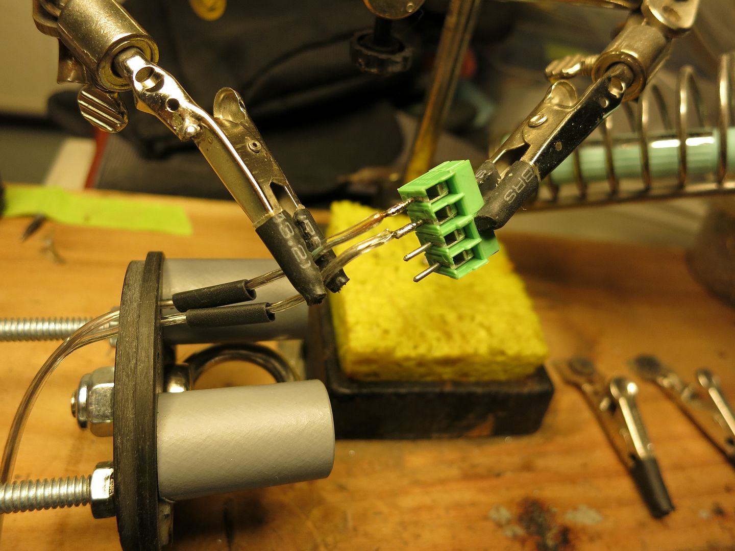
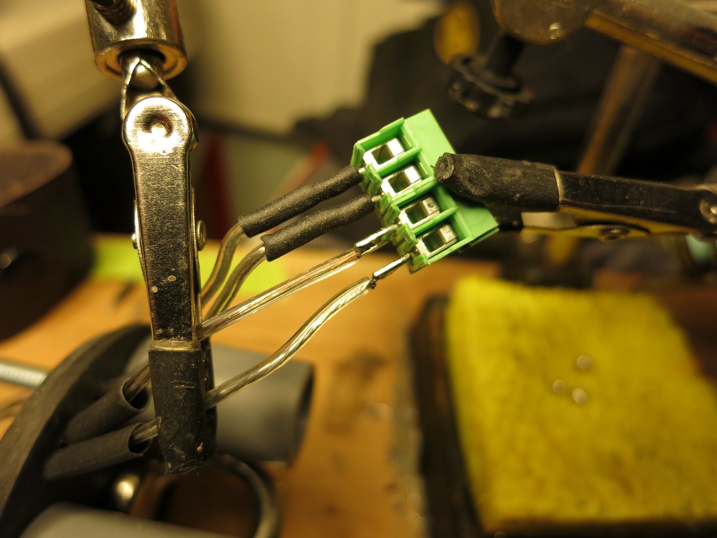
I drilled 7/64 holes and ran 24 gauge wire through, then added heat shrink. Here I'm soldering the terminal block in place:
021_1.jpg


024.jpg

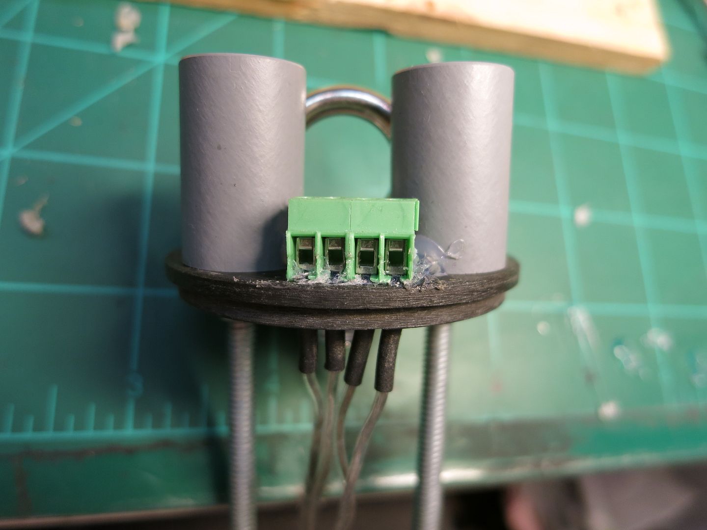
I seat the TB onto the bulkplate with hot glue. Makes it easy to remove them later when they get melted/corroded from use. Here is what it looks like before clearing out the openings:
027.jpg


A small flat bladed screwdriver removes the glue before it hardens:
028_1.jpg


The TB is pretty close to the edge here, so I might have to do some creative modifications to fit the ematch wires in.
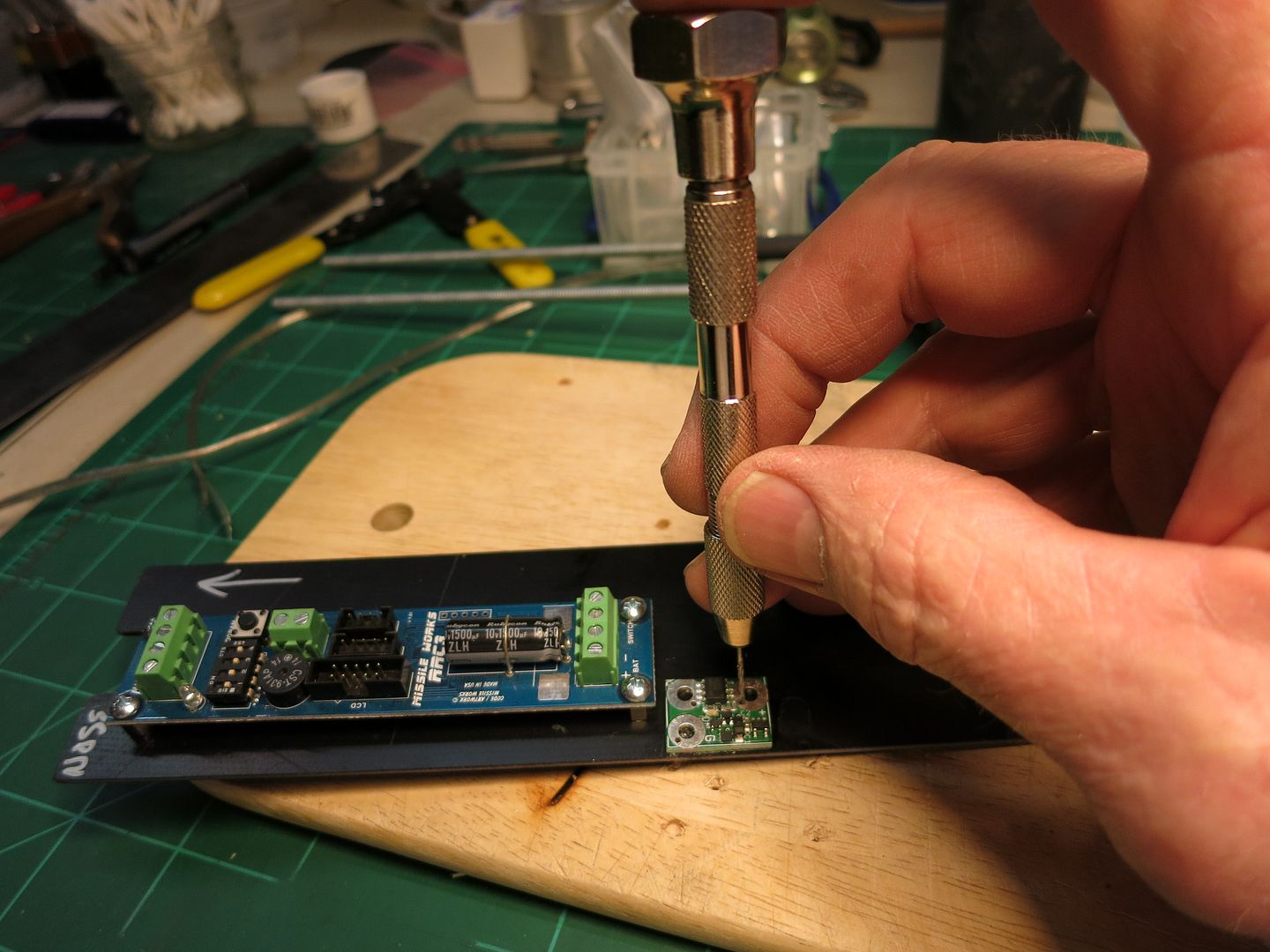
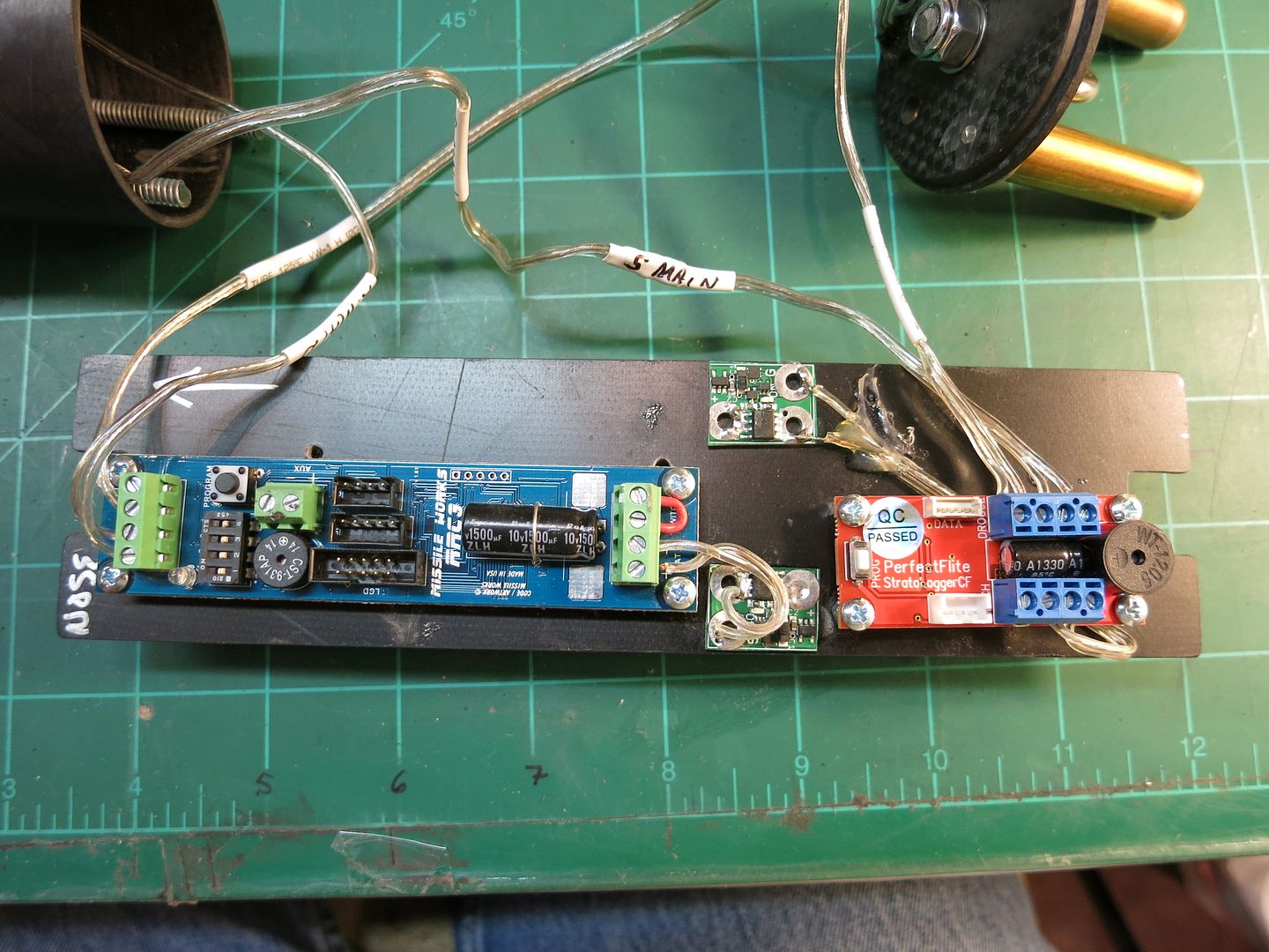
I'm currently mounting the RRC3 and magnetic switch to the sled using 4-40 stand offs I get from Perfectflite. The 9v batteries will fit on the other side of the sled, so I drill through holes and attach the wires through the sled:
030.jpg


Today I'm hoping to finish the custom battery box, more pictures coming.


....
 
So the carbon fiber will not interfere with the mag switches? I was going to use WIFI switch but lost signal once the AV bay was enclosed in airframe.
 
So the carbon fiber will not interfere with the mag switches? I was going to use WIFI switch but lost signal once the AV bay was enclosed in airframe.

I used the same magnetic switches on my Mongoose 75, they work fine. The rare earth magnets supplied with the switches are very strong. I don't think carbon fiber interferes with magnetic waves like it does with RF waves.

Just curious why you decided to use dual altimeters.

I had my first 54mm minimum diameter rocket smack in when an ematch failed ignite and deploy the drogue at apogee. After that event, I decided that any rocket I could squeeze two altimeters into would have redundant systems. After the unfortunate event in California, I think we should all try to make our recovery systems as flawless as possible. Between Sharon and I, we have twenty two dual deploy rockets, most of which are redundant. My last failed DD flight was the one mentioned above, on Nov. 11th, 2014. Since then, we have flown over 50 successful DD flights, including four with the 54mm MD rocket that smacked in.
 
I had my first 54mm minimum diameter rocket smack in when an ematch failed ignite and deploy the drogue at apogee. After that event, I decided that any rocket I could squeeze two altimeters into would have redundant systems...
Thanks. I had a suspicion the reason was based on a failure, but I just wanted to be sure.
 
One comment on your terminal blocks Fred. Duct tape. No really, Duct tape. Slap a strip over them once you get the ematches screwed in and it will offer some protection with "backflash" from the powder. Kurt Savegnago


The TB is pretty close to the edge here, so I might have to do some creative modifications to fit the ematch wires in.
I'm currently mounting the RRC3 and magnetic switch to the sled using 4-40 stand offs I get from Perfectflite. The 9v batteries will fit on the other side of the sled, so I drill through holes and attach the wires through the sled:
030.jpg


Today I'm hoping to finish the custom battery box, more pictures coming.


....


Good stuff Wayco. Are you using standoffs on you magnetic switches? It did not appear so in the photo. Also, when you are done wiring everything up, could you post some good photos of the magnetic switches? I have a magnetic switch on a rocket, but am not very happy with how I have it set up.
 
One comment on your terminal blocks Fred. Duct tape. No really, Duct tape. Slap a strip over them once you get the ematches screwed in and it will offer some protection with "backflash" from the powder. Kurt Savegnago

Allen :)tongue:), Wayne and I use green masking tape to cover the terminal blocks to protect them after the ematches are inserted. The green tape leaves less residue than duct tape IMHO.
 
Allen :)tongue:), Wayne and I use green masking tape to cover the terminal blocks to protect them after the ematches are inserted. The green tape leaves less residue than duct tape IMHO.

That'll work too! With my thin-walled cardboard rockets with free canisters epoxied on the end of the ematches to hold the powder. If I do a "blow-up" the sustainer tube deal I put a foam rubber centering collar around the canister. I believe that cuts down the "blow-out-the-side-events". Yeah charge holders are better and I don't mind the "blow-down" the sustainer to get the drogue out but in that case of a larger diameter rocket, it's easy to pull the cord and drogue out 'cause the fit is not so tight. AKS:wink:
 
Good stuff Wayco. Are you using standoffs on you magnetic switches? It did not appear so in the photo. Also, when you are done wiring everything up, could you post some good photos of the magnetic switches? I have a magnetic switch on a rocket, but am not very happy with how I have it set up.
My statement regarding the mag switches in the previous post is misleading, I only use standoffs on the altimeters.

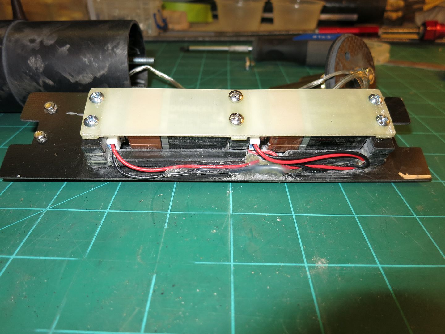
Finished up the avbay sled and lids:
017_2.jpg


I just hot glue the magnetic switches to the sled, and drill small holes through to attach the wires from the batteries. When you attach the switches, set them back a little from the edge, it helps keep them from hanging up when sliding the sled into the coupler. The battery box is from some 3/16" fiberglass flat stock I cut up with my wet saw and the lid is just 1/16" scrap fiberglass. The screws holding down the lid are 1/2" 6-32 and I tapped the holes through the fiberglass blocks.Wires are tacked down with hot glue.
020_3.jpg


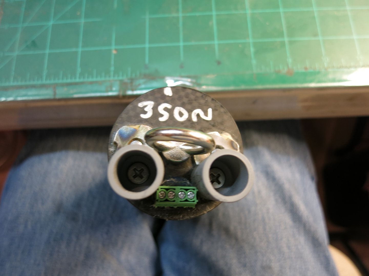
For the charge cups on the "Main chute" side, I used Dog house Rocketry 1.5 gram cups, and tap threads into the lids so the screws can be cut off flush on the inside. The terminal blocks are hot glued down with holes drilled through the lid, then sealed on the inside with hot glue. For those of you that notice details, I removed the terminal block and re-positioned it further back from the edge.
012_3.jpg


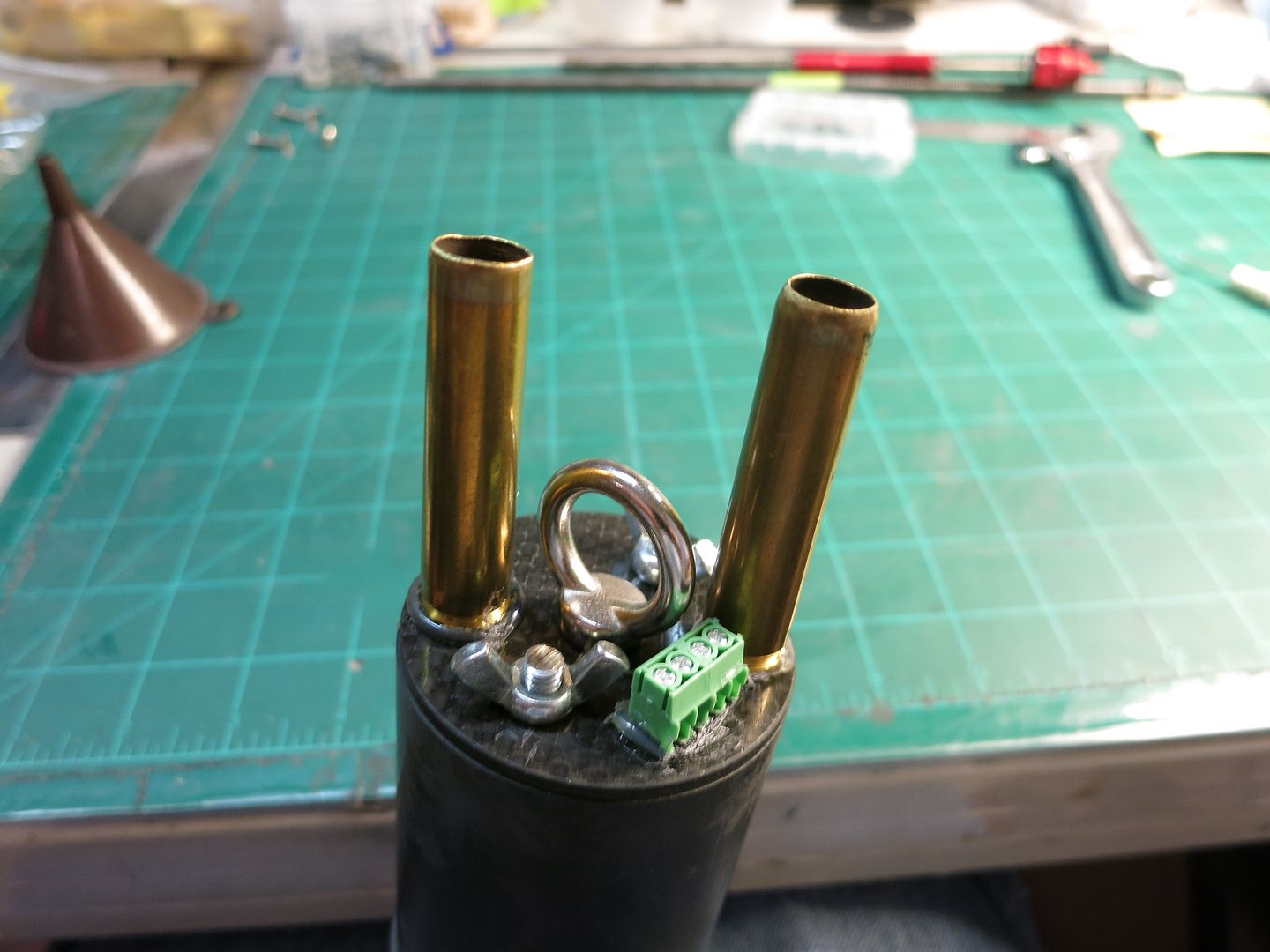
On the drogue side, I use 30-06 rifle brass. Drill out the primer hole for the 6-32 screws and attach them like the Dog house cups. I grind off the tapered end of the brass to make it easier to add black powder and e-matches.
008_3.jpg


If you use rifle brass, be careful with your e-match wires, wrap a bit of electrical tape on the wires where they bend over the sharp edge of the shell. The eyebolts come with the kit, and fit in perfectly.
 
Man Wayne, That nosecone tracker is going to get a workout with this one. Am hoping in the near future I'll be able to say there's a free real time tracking solution for the EggFinders that doesn't require an active internet connection for maps
like the Android app GPS Rocket Locator.

It's the Ham Radio program called YAAC (Yet Another APRS Client) but one doesn't need to be a ham to use it. It works now running under java/Linux but the Bluetooth pairing is not working in java/Windows.
The author is aware of this and is wanting to correct it as he desires the program to be usable with some Bluetooth Ham radio devices in Windows.
There is the potential of investing in a small $70.00 or less windows tablet with a cheap outboard bluetooth GPS device and have a real time mapping tracker for the EggFinders. If one has an Android phone with GPS, could likely use a free GPS tether program to send your position to the Windows tablet so they wouldn't have to buy an outboard B/T GPS.
I'm a proponent of not touching the data and it's highly desirous to have all the data analyzed and plotted automatically so the only thing one has to do is make the two icons come together on the map to effect the recovery.
The software and a portable map is free so the price is right. Plus still have the EggFinder LCD screen for manual backup for the data. Again, I was looking for a portable map so one wouldn't have to rely on a live internet connection.
Yes I know out West you can drive everywhere and a map is not so important. In the farmland flying fields it can be a big help to plot a course to the recovery site

Kurt Savegnago

https://aprs.fi/#!mt=roadmap&z=11&call=a/QCRS&timerange=3600&tail=3600
 
Thanks Kurt, I think I understand what you are trying to do, but wouldn't even try to figure it out on my own. Maybe if you get it all worked out before we go back to Kansas, I will give it a try.
 
Wayne,

Unless you have a Linux laptop with java installed, wait until the author of YAAC gets the bluetooth bugs out of it for
Windows use. Some pictures of this working in Linux is in this thread: https://www.rocketryforum.com/showt...apping-Tracking-program&p=1534933#post1534933

There is another hack with APRSIS32 but holee molee, it's really tough as is the fix for the Linux tracking program
Xastir. YAAC will be a very easy remedy compared to these two programs that I can get down to a one page instruction sheet. Kurt
 
Wayco...

What vendor do you use that supplies those feed-through TBs show in post #62? Mfr & model #?

Also, what size, type & length of shock cord are you planning to use with the MG54? Braided Kevlar? It seems packing space may be at a premium.
 
Wayco...

What vendor do you use that supplies those feed-through TBs show in post #62? Mfr & model #?

Also, what size, type & length of shock cord are you planning to use with the MG54? Braided Kevlar? It seems packing space may be at a premium.

I get the terminal blocks from Mouser.com, and their part number is 651-1984633. Remember that the CF avbay lids are conductive, so you have to insulate the posts where they go through. Next time I do something with CF, I'm replacing the lids with the fiberglass stepped lids that RW sells.
1/4" braided Kevlar, I get mine from Wildman, but there are plenty of vendors that carry it. My rule of thumb is 3x the length of the rocket for shock cords. I will adjust this somewhat depending on the application. The Mongoose has more room than the Blackhawks do, but you still need to be careful, especially with the drogue.

Update on my build, I'm starting on the nosecone now, adding bulk plates to the coupler and soldering another Eggfinder together today...
 
I get the terminal blocks from Mouser.com, and their part number is 651-1984633.... Update on my build, I'm starting on the nosecone now, adding bulk plates to the coupler and soldering another Eggfinder together today...
Thanks for the info and update.

I just finished my upper airframe section, also with an Eggfinder GPS NC. Photos attached...
MG54_Upr Airframe_012916.jpg MG54_NC_GPS_SA_012916.jpg
The NC coupling nuts were epoxied to the NC and then a FG cloth strap overlaid on top.
 
Last edited:
Nice,

How in the world did you get the coupling nuts to line up with the holes in the bulkhead? Did you put a short segment of threaded rod in them after they set up, Put ink or paint on the ends of the rods and made an impression with the bulkhead?
Drilled where the ink/paint mark was? Kurt
 
How in the world did you get the coupling nuts to line up with the holes in the bulkhead? Did you put a short segment of threaded rod in them after they set up, Put ink or paint on the ends of the rods and made an impression with the bulkhead? Drilled where the ink/paint mark was? Kurt
First I rounded the wrench facets on the nuts using a grinding wheel - leaving sufficient ridges for the epoxy to grab onto.

Having marked the coupler diameter (180° marks, with axial lines to ensure the coupler nut was parallel to the coupler axis, and depth lines to ensure the coupler nuts were at the same depth from the coupler's edge), I epoxied each nut onto the coupler - used a thin bamboo skewer through the hole as a alignment guide to the axial marks.

Once both nuts were set, I placed the bulkhead onto the coupler nuts and from the backside marked the drill position of the bolt holes using the method you noted above - a paint mark.

I used a 1/8" bamboo skewer (tip was blunt rounded to produce a nice clean mark) that was lightly dipped into white acrylic paint, and passed through the back side of the nut.

I should note that the coupling nuts and socket head bolts are SS 10-24 thread. The bolt length is 7/8".
 
Wayco...

I've gone over the photo and notes in post #1, but before I start drilling into a very expensive 40" CF tube I'd like to know I've understood the PEM nut installation process - this will be my first time using them.

I've taken the liberty of editing your photo for the sake of this post. In my case I will be drilling into an aluminum AeroPack 54mm MD internal retainer:

After positioning the retainer and drilling the first 9/64" hole, insert the 6-32 machine screw and drill out the remaining 2 holes. Remove the screws, and drill out the holes in the retainer to 7/32". Now place the PEM nut on the inside of the retainer (properly oriented), and install a 6-32 screw (with a flat washer) from the outside of the retainer. Screw in the 6-32 screw until the PEM nut is pressed into the retainer. Remove the screw and repeat with the other retainer holes.
M54E.jpgPEM Nut Install02.jpgInstallationProcedure2.jpg

Did I miss anything? BTW, what is the size, model no., and vendor source for the PEM nuts?

Thank you...

01/30/16 Addition - Reviewed the PEM nut specs for the 6-32 thread nut for compatibility with the AeroPack 54 MD retainer - wall thickness & material hardness (important factors). You may have used the type FEX-632 nut as the kit's CF coupler wall thickness is ~0.077". However, the MD54E wall is only 0.044", which is below the 0.059" FEX-632 specs. In my case, I should be using a FEOX-632 which accepts wall thicknesses between 0.039-0.045".

The MD54E is made from 6061-T6 aluminum having a Rockwell B hardness of 60 and that is below the PEM nut spec of 70 (max).

Lesson: One size does not fit all... :wink:
 
Last edited:
I get my PEM nuts from Missleworks:
https://www.missileworks.com/store/#!/PEM-Nuts/c/5760492/offset=0&sort=normal

If you have never installed them before, I would suggest you try them on a scrap piece of fiberglass first. As I stated in my first post, I use the nut to draw the pem nut into the fiberglass coupler, it can exert more force than the screw can.
Another option would be using plastic rivets, most vendors carry them, I know Wildman does. If you are concerned with the clearances and thickness of the AP retainer, the rivets might work better for you.
 
I get my PEM nuts from Missleworks...If you have never installed them before, I would suggest you try them on a scrap piece of fiberglass first... If you are concerned with the clearances and thickness of the AP retainer, the rivets might work better for you.
I do want to practice with them first and have some scrap aluminum for that purpose. Although I like the idea of the countersunk machine screws, I'm moving towards using 0.203" dia. plastic rivets - they have a smooth, low profile and would be easier to install.

I do appreciate your starting and maintaining this topic - it promotes thinking and allows for discussion - thank you!
 
Last edited:
Made a decision and installed the AeroPack MD54E retainer with plastic rivets (McMaster-Carr # 91020A198). These are not the size I first thought I would use. After measuring the combined wall thicknesses I found, the 0.203" dia. rivets were too long and were not available in shorter lengths. So I used 0.163" dia rivets, which needs a 4.2mm drill hole.

I already had the retainer's position marked out and the aft end of it has a 1" depth to the central support plate. So I marked a spot at 1/2", drilled a pilot hole, and then the 4.2mm hole. Did the same with the CF airframe, inserted the retainer, and locked it down with a rivet. Drilled-out the remaining two holes and installed those rivets. The retainer is now solidly positioned, but removable. Took all of ~5 min.

I'm very glad I took the time to reconsider my initial plans. Thanks to Wayco's patience...:smile:
 
Made a decision and installed the AeroPack MD54E retainer with plastic rivets (McMaster-Carr #91020A198). These are not the size I first thought I would use. After measuring the combined wall thicknesses I found, the 0.203" dia. rivets were too long and were not available in shorter lengths. So I used 0.163" dia rivets, which needs a 4.2mm drill hole.

I already had the retainer's position marked out and the aft end of it has a 1" depth to the central support plate. So I marked a spot at 1/2", drilled a pilot hole, and then the 4.2mm hole. Did the same with the CF airframe, inserted the retainer, and locked it down with a rivet. Drilled-out the remaining two holes and installed those rivets. The retainer is now solidly positioned, but removable. Took all of ~5 min.

I'm very glad I took the time to reconsider my initial plans. Thanks to Wayco's patience...:smile:

So you now have 54mm motors being retained by three 3/16" plastic rivets? Are you sure you want to do that?
 
So you now have 54mm motors being retained by three 3/16" plastic rivets? Are you sure you want to do that?
This option is something that could be altered. I can still epoxy the retainer in that position. But let's discuss your concern.

The motor's thrust will be transferred by the motor case closure ring to the circumferential longitudinal axis of the CF airframe (very strong). The motor will not have any ejection charge, and the rivets will withstand the drogue separation charge similar to what occurs with typical dual deploy main chute separation.

The retainer is really only keeping the motor casing and expended motor from falling out. What am I missing?

How do you know the motor retention will survive the ejection charge? What is the pressurization of the tube and the forces involved? What is shear strength of 3/16" plastic rivets? Also, it's not just ejection charge forces... What if you have a premature apogee event leading to a more violent separation? Many people figure holding force need at 50 to 100 gees multiplied by the mass you are trying to secure? What is the weight of the largest 54mm spent motor you expect to fly in this rocket (plus the MD retainer assembly also)? You need to figure the forces and do some math to prove it will be OK. I can't say it won't as I haven't done the math (yet, as it's pretty easy). Don't know where the suggestion came from, but I have never seen anyone use, in effect, plastic pins to secure their motor hardware.
 
Last edited:
How do you know the motor retention will survive the ejection charge?
Good question. Here's my answer. The drogue ejection charge to produce a 15 psi compartment (11.5" x 2.152") pressure is 0.32g BP. Increasing that charge to 0.5g creates sufficient force to shear two 2-56 nylon shear pins (83.2 LBF) in that section should I opt to use them.

The tensile strength of Nylon 6/6 (rivets are nylon not styrene) ranges 10,500 to 12,400 psi. Using the conservative value of 10,500psi, and a shear strength of 60% of the tensile strength, the shear force required for one rivet (0.163" dia) is 131.5 Lbf. With 3 nylon rivets the total shear force is 394.4 Lbf - 474% more that than that created by the drogue ejection charge.

While apparently few (if anyone) has used plastic rivets in a MD rocket, it appears that it may be a reasonable alternative to other methods. In fact it was Wayco who first suggested the notion to me...

OK, if you feel comfortable, I certainly want it to work for you.

Although maybe an outlier, you might also take a look at an extreme event such as a recovery anomaly that I mentioned before. The G-forces can surprise you.

Let us know how your flight(s) go.
 
While apparently few (if anyone) has used plastic rivets in a MD rocket, it appears that it may be a reasonable alternative to other methods. In fact it was Wayco who first suggested the notion to me...

I use them.

On everything from 29mm minimum to 7.5 in rockets.....just 3.

Never had a failure or issue of any type & I put them through hell!
 
Back
Top