Estes Announces 1/45 Little Joe II !!!!

The Rocketry Forum

Help Support The Rocketry Forum:

This site may earn a commission from merchant affiliate links, including eBay, Amazon, and others.
ifZ34YN.jpg


I’ll post more about it later. Anyone have any questions?

- George Gassaway


Yes...do the fins look in proper scale to the body width/length?...they seem a tad small in the picture here.
Maybe the white reflection is making the body tube appear larger.
 
Last edited:
Attached is a full scale top view template of the Little Joe II with it's fins attached. You might want to use it to align the fins when gluing them in place.

Really nice. Thanks for posting that.


Yes...do the fins look in proper scale to the body width/length?...they seem a tad small in the picture here. Maybe the white reflection is making the body tube appear larger.

Well, I have not measured, I ought to (Away from workshop right now). But in any case, by coincidence of the pose, the body is rotated so that you are seeing the fins at a 45 degree side view. So, they look shorter than in the classic 90 degree side view you may be expecting.

See drawing below that shows it rotated at 45 degrees to interface with a drawing Tom Beach made of the launch pad.

UPDATE - Measured the fins. Total span correct, tip chord correct, fin root fairing a tiny bit short (2%).

BTW - extra credit for the first person to hinge the elevons and install a servo into each fin/fairing assembly to allow for onboard guidance to steer it like the real thing (let's go for A-004 realism and not A-003 realism). No, I am not hinting at all that I plan to, it just occurred to me as a possible (but not easy to do) thing as I looked inside of the fin assembly.

NOTE: The drawings, personal photos, and other information I write are copyright and not to be posted elsewhere without permission.

- George Gassaway

Pad-Joe.gif
 
Last edited:
Well, I have not measured, I ought to (Away from workshop right now). But in any case, by coincidence of the pose, the body is rotated so that you are seeing the fins at a 45 degree side view. So, they look shorter than in the classic 90 degree side view you may be expecting.

See drawing below that shows it rotated at 45 degrees to interface with a drawing Tom Beach made of the launch pad.

- George Gassaway

Good point.
My order for one is in.
Looking forward to getting mine.
 
I am beginning building one of the kits. Wonder if I should post photos and notes here, or do a separate build thread either in LPR or in the “Scale” section?

BTW - For possible clustering, such as A-003 taking off on three C6's, an 18mm motor will not fit inside the scale nozzles. I should have checked the dimensions long ago to check the size. I was not really planning to build my first kit to cluster anyway, but did check it out. To do an 18mm cluster, looks like 3 options:

No scale nozzles at all.

Build so the kit nozzles can be on for display and removed for cluster flight.

Make custom nozzles, such as cardstock cones soaked with CA or thin epoxy, and simulating the flexible dark covering that was over the angled nozzle throat area, and try to strike a balance so that larger nozzles don't look cartoonishly big.

OK, 4th option.... some enterprising person draws up a 3D nozzle assembly that would allow for an 18mm motor to fit, and 3D prints them for sale. But the price for 6 of those would probably be more than the kit (or buy one set and mold copies).

In the image below, the topmost example is a nozzle assembly stuck together the outer end of the nozzle facing an 18mm engine (at its widest, it's about the diameter of a BT-20). In the lower example, half of a nozzle showing that an engine will fit inside for some distance, probably another 1/8" if the alignment pins/holes were Dremeled away after assembly. Could not fire the engine without melting it, but does support the idea of individually removable display nozzles for clustered flight of 18mm motors.

Of course, any clustered model would need a LOT more noseweight.

- George Gassaway

3k7hgzd.jpg
 
Last edited:
Yes, a 13mm tube will fit nicely.

0pjl04u.jpg


The thing is that the model could not fly well on just a cluster of say three A10's, if it was simulating A-003 that flew on three outer Algols (and was going to air-start three more outer Algols but it broke up from out of control spin first). So it would need a big engine in the center for the main thrust, like a D12 plus three A10's.

A-004 took off on Two Algols in the outer locations, two tiny Recruits in the outer locations, and three Recruits in the middle, then air-started two more outer Algols.

Now, the first two LJ-II's, QTV and A-001, had 7 engine clusters. But those flew on one Algol in the center and six Recruits which were very small compared to the Algols. But the biggest issue with those is that they used Fixed fins, without the fin root fairings, so anyone who wants to model either of those has some custom fin-building to do, and some complications with the kit body wrap which is formed at the root area to be used with the long fin root fairings, not the original fins.

Of course, I realize that many are not sticklers for realism. Say for example a model of A-003 that took off on a D12 and three A10's would be cool. And air-starting three more A-10's, even cooler. :cool:

- George Gassaway

4zxvoDL.jpg


S-63-15701.jpg
 
I would love to see you post now as you go George but if this would hurt your
Joy of the build, forget it.

By the way, I've always have enjoyed your personal website and all the info there to.
Thank you!
 
I had to build several models for a Trade Show coming up in a couple weeks and one of them was the Little Joe II. It came out pretty good, but not good enough to enter in a NAR scale competition. More primer, putty sanding of body tubes would be needed to make it really nice, but for something that was going to sit on a shelf, be looked at for a couple of days and then most likely end up in the garbage I figured it was good enough. By the way I ended up cutting vinyl for all those large black squares on the main tube, capsule and launch tower. This was SOOOO much easier to apply then decals. I could make the cad or a pdf file available it someone else wishes to cut vinyl.


John Boren

LJ2a.jpg

LJ2b.jpg

LJ2c.jpg

LJ2d.jpg
 
I have applied the body wrap. I tested first with the 3M Super 90 that was recommended by James Duffy. It came out splattery like a spider-web, did not seem right so I did not use it (I do not know if it was a bad can or is supposed to be like that). So I ended up using 3m Super 77, which sprayed on smoothly. ALWAYS TEST!!! James recommended testing too.

More info later, have to go to the store and do dinner.

- George Gassaway
 
I had to build several models for a Trade Show coming up in a couple weeks and one of them was the Little Joe II. It came out pretty good, but not good enough to enter in a NAR scale competition. More primer, putty sanding of body tubes would be needed to make it really nice, but for something that was going to sit on a shelf, be looked at for a couple of days and then most likely end up in the garbage I figured it was good enough. By the way I ended up cutting vinyl for all those large black squares on the main tube, capsule and launch tower. This was SOOOO much easier to apply then decals. I could make the cad or a pdf file available it someone else wishes to cut vinyl.


John Boren


That would be sweet. It will be nice to have choices once I start the build. I have thought about trying to enlarge a paper wrap that I made for a 1/70 scale Little Joe II
 
I have applied the body wrap. I tested first with the 3M Super 90 that was recommended by James Duffy. It came out splattery like a spider-web, did not seem right so I did not use it (I do not know if it was a bad can or is supposed to be like that). So I ended up using 3m Super 77, which sprayed on smoothly. ALWAYS TEST!!! James recommended testing too.

The web-like appearance of the 3M Type 90 adhesive is what it is supposed to look like, intriguingly. Nothing wrong with the adhesive, just a unique property of the product that I should have mentioned. I'll be doing mine in the next couple of days and will try to do a video.

With that in mind, perhaps we should have a "Little Joe II Pro Tips" thread?

Question for George: do you have a picture that shows the General Dynamics data plaque more clearly? That would be a neat feature to add to a build.

James
 
John,

Could you tell us what brand of silver you used? I must have 4-5 different brands of silver paint, and all are quite different. I think I've got the white chosen, but would not mind knowing what your choice was for the white, as well.

Thanks for all the info and pics you posted!
 
I used Testors Model Masters White, Black and Silver Acrylic paints or this build. They also make an aluminum that might look good as well. For prepping the surface on all my rockets I use Krylon Industrial Tough Coat Light Gray Sandable Primer - S00341. Orange Bondo spot putty fills in all the grain of the wood when I build normal kit type rockets but it can also be used on the spirals of the tubs. I very seldom use conventional sandpaper these days. I start with Sanding sponges, then move too Scotch bright pads and my final surface sanding if you can call it that is with 0000 steal wool. This Primer sands so easily that steal wool can get down into all of the corrugations of the wrap and make everything super smooth.

John Boren


John Boren
 
... my final surface sanding if you can call it that is with 0000 steal wool...

I have used steel wool for years on woodworking projects, but it never occurred to me for model rocket finishing. Now that you mention it, it seems so obvious that this would be another good application.
 
Question for George: do you have a picture that shows the General Dynamics data plaque more clearly? That would be a neat feature to add to a build.

Yeah, already planned to do that, and post it. Better than a picture, a scaleup of a drawing of the plaque, good enough to print out hi-res. I have to find the file and convert it... its from around 1991 using MacDraw and "Classic" Mac OS.

For those who wonder WTH that is, it was a thin very shiny plaque (two places) with black lettering on it, attached at the base. Visible in this cropped version of a picture shown earlier. A low-res inset is included from a different drawing GIF file. I had it on a 1/100 scale model of A-002. I made it by printing the black lettering onto clear decal film, applied the decal onto adhesive chrome mylar, then after drying cut out the whole thing and stuck it into place (well, two of them).

Bottom, the General Dynamics/Convair logo from an old report cover page. The plaque is much the same, rearranged, with Convair below General Dynamics, and no address.

- George Gassaway

MiMjF60.jpg


Qi7tDKm.jpg
 
Last edited:
The plaque is much the same, rearranged, with Convair below General Dynamics, and no address.

This is close, but still not quite right. Turns out that General Dynamics uses a proprietary font. Anyone work for them and have access to it?

Can't help but think that this looks vaguely like a Jeep grille.

James

General-Dynamics-Plate.png
 
The trademarked Jeep grille is seven slots, rather than eight. But otherwise, yes, it does have that look to it...
 
More primer, putty sanding of body tubes would be needed to make it really nice, but for something that was going to sit on a shelf, be looked at for a couple of days and then most likely end up in the garbage I figured it was good enough.
John Boren

Hold the phone a second! I'm about to cry thinking about those beautiful models ending up in the garbage. Your "good enough" looks pretty darn good to me! Why would they be thrown away? Heck I'll take them off your hands if they're just going to be tossed!

Glenn
 
Because every time I build models to display in a show that Estes personal aren't running the booth the models NEVER make it back to Estes and are never seen again.


John Boren
 
George why not just start a build thread?

Well, I'm torn between a separate build thread, and the "groupthink" in this thread. Of course, a separate build thread could be a "GroupBuild" thread.

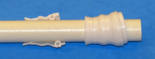
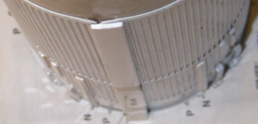
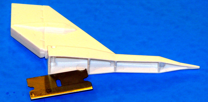
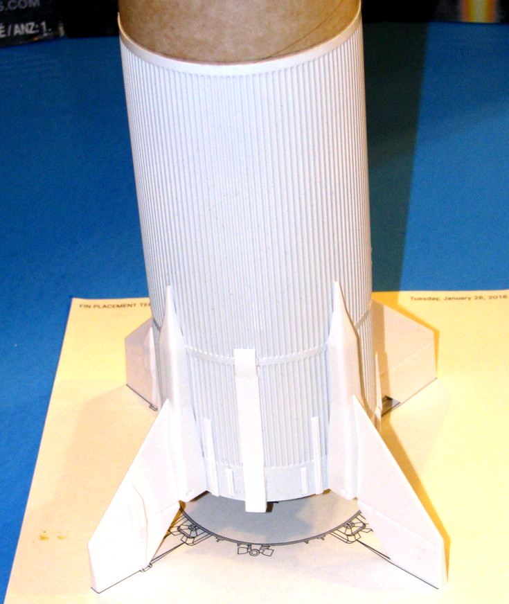
But here is an example of something of general interest. Now, for one, I should have tried to apply more adhesive along the two edges, if I had tried I'd have probably sprayed some excess into a cap to capture it in liquid form and carefully use a small brush to apply by hand. Anyway, the seam was OK at the time I applied the system tunnel. I was surprised to find that the long system tunnel was not aligned in the middle of the seam. It's aligned mostly to the seam, with only one edge touching one corrugation top on the left. I came back later to find this:

4K2uACI.jpg


It has pried out a bit. Now perhaps if I had used an elastic bandage or something to hold the whole thing compressed. But, anyway, what I will try to do to fix it is to carefully apply a bit of CA underneath and press together.

For a future model, I might just apply the tunnel one corrugation to the left, so the tunnel can act more like an external splice. Although if I can get a better bond along the edges to begin with, it would not matter as much.

That is not the only thing but one example. So does that seem suited for a separate build thread or this thread?

But, I am taking a LOT of photos of various steps, and if I posted lots of those in this thread it could get pretty gnarly. So, perhaps a separate thread and note the occasional odd stuff here?

I would love to see you post now as you go George but if this would hurt your
Joy of the build, forget it.
Well, I never enjoy building rockets.... but you can't fly 'em if you don't build 'em (unless RTF). :)

Hmm, how can I phrase this.... I'm not UNenjoying this as much as other builds? :)

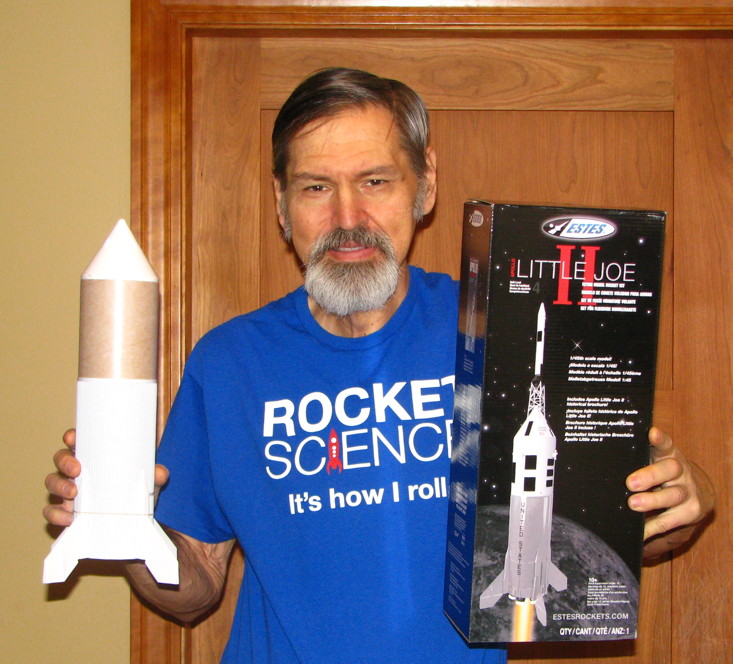
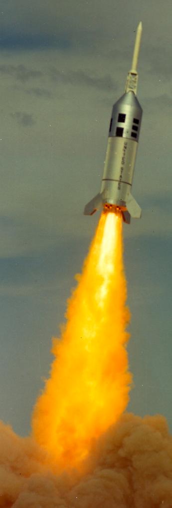
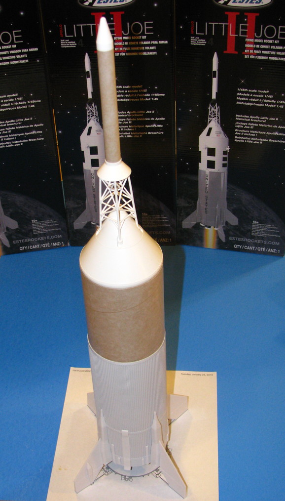
And man it sure makes a difference to be building a Little Joe-II of this size, from a kit, and not a scratch-built one.

I'm excited regardless. And on some level I am having fun building it even if it's more subconscious than anything else. There is probably only ONE other kit that I could get this excited to build, and I'm not going to say what so as not to jinx it.

And indeed right now there are some other projects that need attention.... but regardless I'm finding the time to build one anyway.

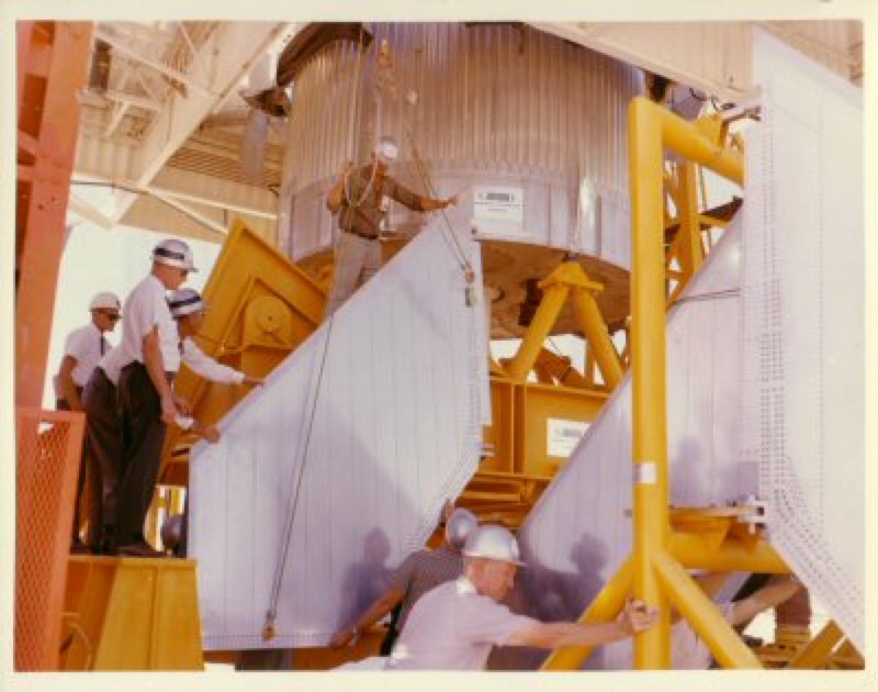
So, this is such a UNIQUE situation. Yes, I'm reliving building a 1/45 Joe much like I did in 1975. But unlike 1975... I actually know so much about the real rocket now. So I appreciate it on that level too, and can share some info most don't know as much about.

So, more of the fun in this is sharing the info. And also, I am taking the approach of building this as a "fun" model to sport fly. I'm not trying to make it judge-worthy. And so the occasional "oops", ah, no big deal. But also can learn from the first one to try to do better next time.

Likewise, not putting a lot of time into the build, I won't be as leery of simply sport flying it. I never sport fly my contest-worthy sport models (Well, my X-1 was a unique exception, a sport model I entered at NARAM for the heck of it and due to mission points and DQ's by others it moved from 5th to 1st).

I do want to note that it was Tom Beach who compiled the massive amounts of raw data starting in 1983, then shared so much of it with me in 1989 that I began to draw it up and we collaborated..... without internets or even Compuserve (I wasn't online at all till after the data project was over... we were mailing floppy disks back and forth, I'd draw mot of it, he'd review, make notes, sometimes his own tweaks to the drawing files, etc. And he made a few drawings of his own. Oh if only I had e-mail back then, Tom already did).

So, whatever level of knowledge I have about the Little Joe-II will never be as much as Tom knows.

https://georgesrockets.com/GRP/Scale/DATA/Tom.htm

- George Gassaway

FTjnv20.jpg


- George Gassaway
 
Last edited:
I’ll catch up on the various steps later, calling it a night. But basically, the Joe Body wrap has everything glued to it except for 2 fins and launch lugs. Tower struts glued together, but otherwise the capsule/tower/ and LES rocket are just plugged together, not glued. Remaining fin halves glued to each other, and six Algol nozzles assembled. I simply placed two Algol nozzles into holes in the centering ring for now, not glued.

- George Gassaway

eHTU67R.jpg
 
Last edited:
I believe I mentioned about the alignment of that seam with the tunnel. At one point it was more centered under that tunnel, but a screw up by me left us with what we have now. I'm sure one day someone will figure out the screw up, but I'm not telling until then.

Also a little CA glue run along that seam does wonders to hold it down.

John Boren
 
I had to build several models for a Trade Show coming up in a couple weeks and one of them was the Little Joe II. It came out pretty good, but not good enough to enter in a NAR scale competition. More primer, putty sanding of body tubes would be needed to make it really nice, but for something that was going to sit on a shelf, be looked at for a couple of days and then most likely end up in the garbage I figured it was good enough. By the way I ended up cutting vinyl for all those large black squares on the main tube, capsule and launch tower. This was SOOOO much easier to apply then decals. I could make the cad or a pdf file available it someone else wishes to cut vinyl.


John Boren

Hi John,

A PDF of the black squares would be great for me. I have some spare black vinyl laying around and a little fiskars cutter that will serve my purpose.

Cheers,
Michael
 
John, that wold be nice if you did post a pattern for cutting out vinyl for markings. I used some CriCut black vinyl last fall for another project and it should work well (used 40% off coupon at Michaels).

I am going to use printed paper wraps, at least for the SM (this is why I did not use primer on the tube). I need to modify a file from the old Little Joe-II drawings. When done, I’ll post them for anyone who wants to use them. They’d also be useful as an alignment template for applying vinyl.

Argh!!! My Canon camera stopped working. May be a few days without it. And my iPod Touch’s camera is not as good. But at least before the Canon went out I got a photo of something I wanted to show.

Inside of the fin root fairings, there are some circles sticking out (inwards), probably where the ejector pins are located in the mold. One in the lower bay, and two a couple of bays up (to the right in the photo). They interfere with the fit of the alignment and glue tabs on the body wrap, try to push the fin assembly away. So, I recommend carefully cutting out those circles (6 per fin assembly), at least for the depth needed to no longer interfere.

In the image below I played with the contrast and brightness to make those other two circles more visible.

MwHvjwi.jpg


OK, my camera is working again but it's intermittent.

The model with the 4 fins glued on. The other parts just plugged together for the pic. Model is standing on top of a printout of the drawing John Boren posted for fin alignment.

- George Gassaway

cB7ObzL.jpg


uVmsXse.jpg
 
Last edited:
What kind of glue do you all use on these Estes kits these days? I have not built one since the early '70s & I don't remember any plastic parts back then.
 
Back
Top