- Joined
- Jan 17, 2009
- Messages
- 5,204
- Reaction score
- 1,547
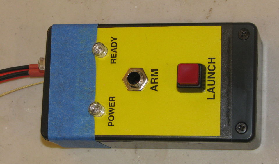
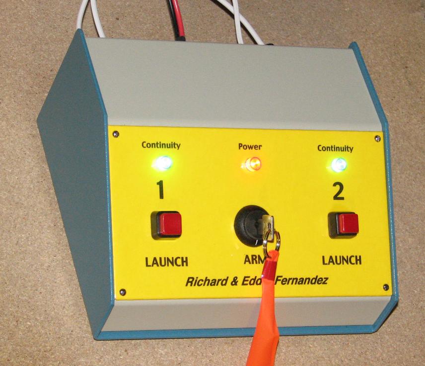
FWIW - A small launch control I recently made for someone (blue tape is covering their name and NAR #).

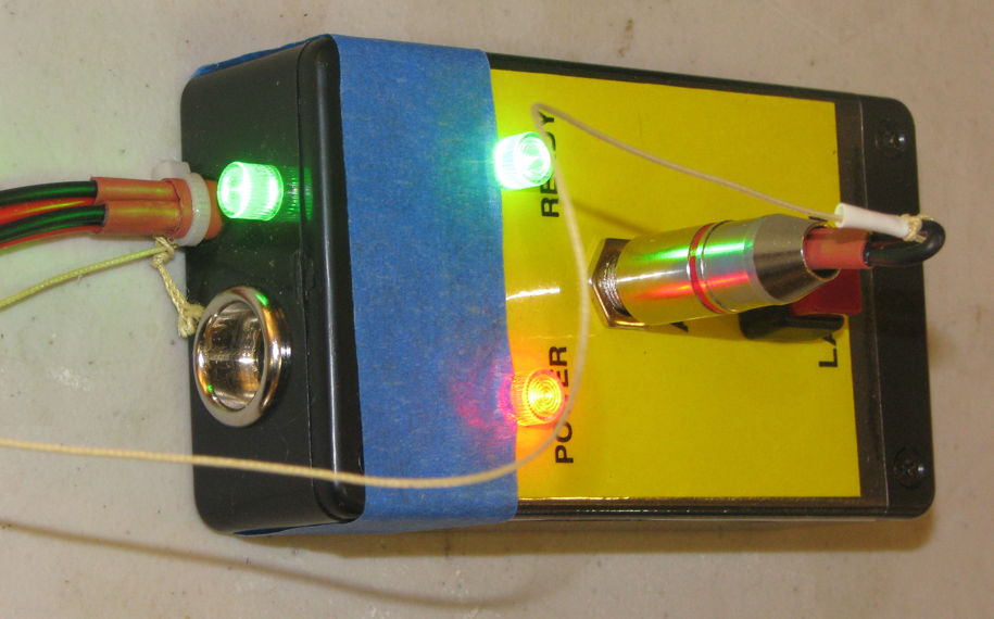
Super-bright LED's (using a dropping resistor) with CLEAR Cliplite holders from All Electronics to scatter the light for better viewing angles. By being clear, it is obvious when they are lit because either red or green is seen if lit, if still clear (with no color) then they are not lit. Otherwise , if the Cliplite holders were translucent red or green plastic, on a sunny day it would not be easy to know for sure if the LED's were lit up or the sun was illuminating them (for similar reasons, the LED's themselves are water-clear).

Also a Piezo Beeper is driven in series by a blinking LED to make it beep for continuity. I've used that blinking LED method for many years, super easy way to get a beep-beep-beep (the blinking LED itself is hidden inside, can't hold a candle to the super-bright water clear LED's).
18 second Youtube video here:
https://www.youtube.com/watch?v=JF8WmMLUuto
To keep the continuity current low (10 mA), the two green LED's, plus piezo beeper, are driven by a transistor that is activated when there is continuity (using a 1000 ohm resistor to drop the current going to the transistor). So, the actual current thru the ignitor is 10 mA, and goes to the transistor with the 1k resistor. The transistor then powers, in parallel, the green LED's and Piezo beeper/Blinking LED.
It works on 12V. Power source will usually be 3-cell Li-Poly batteries (11.1 V), from 2200 to 4000 mAh capacity.
I know that a 1/4" Phono plug is not good for carrying a lot of current. But they will mainly be using this for Solar Ignitors and Q2G2 ignitors, not clusters. I have seen problems with RCA connectors used as Safety keys, mainly the chassis jack coming loose, causing it to lose electrical contact inside. I've often used actual key switches, but for various reasons, did not for this.
- George Gassaway

Super-bright LED's (using a dropping resistor) with CLEAR Cliplite holders from All Electronics to scatter the light for better viewing angles. By being clear, it is obvious when they are lit because either red or green is seen if lit, if still clear (with no color) then they are not lit. Otherwise , if the Cliplite holders were translucent red or green plastic, on a sunny day it would not be easy to know for sure if the LED's were lit up or the sun was illuminating them (for similar reasons, the LED's themselves are water-clear).

Also a Piezo Beeper is driven in series by a blinking LED to make it beep for continuity. I've used that blinking LED method for many years, super easy way to get a beep-beep-beep (the blinking LED itself is hidden inside, can't hold a candle to the super-bright water clear LED's).
18 second Youtube video here:
https://www.youtube.com/watch?v=JF8WmMLUuto
To keep the continuity current low (10 mA), the two green LED's, plus piezo beeper, are driven by a transistor that is activated when there is continuity (using a 1000 ohm resistor to drop the current going to the transistor). So, the actual current thru the ignitor is 10 mA, and goes to the transistor with the 1k resistor. The transistor then powers, in parallel, the green LED's and Piezo beeper/Blinking LED.
It works on 12V. Power source will usually be 3-cell Li-Poly batteries (11.1 V), from 2200 to 4000 mAh capacity.
I know that a 1/4" Phono plug is not good for carrying a lot of current. But they will mainly be using this for Solar Ignitors and Q2G2 ignitors, not clusters. I have seen problems with RCA connectors used as Safety keys, mainly the chassis jack coming loose, causing it to lose electrical contact inside. I've often used actual key switches, but for various reasons, did not for this.
- George Gassaway
Last edited:


