Ultrafast G80T

The Rocketry Forum

Help Support The Rocketry Forum:

This site may earn a commission from merchant affiliate links, including eBay, Amazon, and others.

Faraday's Cage

Active Member
Joined
Sep 25, 2009
Messages
27
Reaction score
0
After having completed my first scratchbuilt rocket (see the medium power rocketry forum), I am now working on my next one. I tried to make the fastest possible design using a G80T. Rocksim predicts the maximum speed to be Mach 2, although the design would probably need new fins after every launch. It uses streamer recovery, max altitude 6250 ft and the predicted distance from launchpad in 3-7 mph winds is 1000 ft. I plan to fabricate almost everything myself (not sure about the nosecone though).

Here
is the design file (Rocksim).
________
Honda C200
 
Last edited:
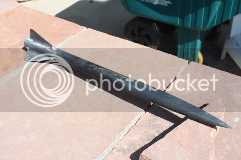
Looking at that file, the fins are a terrible shape for supersonic flight (you want them swept backwards to minimize wave drag), and a conical nose is not all that ideal either. If you're looking for maximum velocity, you want something that looks a lot more like this:

IMG_0281.jpg


Also, in all honesty, mach 2 is pretty optimistic for a G80T - mach 1.2 or so is much more likely. Rocksim often overestimates at higher speeds.
 
But wouldn't the mach cone be outside of the fins anyway? And there are supersonic aircraft with forward-swept wings.

Also, did you see the old version, or the updated one?

A screenshot of the one with the updated fins is attached. I optimized it to increase the contact area (amount of fin touching fuselage) because I was afraid that the fins would rip off.

By the way, since you seem to know a lot about aerodynamics, could a Busemann's Biplane be used for fins on a rocket?
________
buy volcano vaporizer

mach2.jpg
 
Last edited:
The leading edge of the fins will create a shock as well, and you want to keep the sweep angle greater than the mach cone angle if possible. Straight fins will work, but a swept delta will be stronger and lower drag for the same fin area. It will also be less likely to flutter, the most common failure mode for model rocket fins. As for the design I saw, I think it was the first version - that one you have now is better (though still not ideal). What are the small protrusions at the fin tips for?

As for the Busemann's Biplane, as far as I know, it is designed to produce no lift, and as such might pose a challenge for fins. It would also require a high degree of precision and stiffness in construction. I'd stick with standard fins for now honestly - I'd be surprised if you could get it to work even close to as well as normal fins.

Another thing to consider - if you're going for maximum speed, you want to minimize drag. A conical nosecone is a terrible idea to do that. Ideally, you would have something like a Von Karman shape (the shape used in the rocket I used as an example in the above post). Adrian Adamson, maker of the Parrot altimeter (and owner of that rocket shown above, which has successfully achieved >M2.0) has done some tests showing that a conical has a significantly higher drag rise at transonic speeds than a von karman (a fact that Rocksim does not properly account for). Honestly, I would try to mimic the shape of the rocket above as much as possible - it is very close to the optimum for mach 1.5-2.5 flight. If you want a lot of information, you could PM him - he is Adrian A on the forums, and is among the most knowledgeable people I know on extremely fast and high flight with relatively small motors.

Very glad to see that your college education is in no way being wasted!:)
 
What are the small protrusions at the fin tips for?

The small protrusions bring the CP backwards by the tiny amount that Rocksim needs to consider it stable.

As for the Busemann's Biplane, as far as I know, it is designed to produce no lift, and as such might pose a challenge for fins. It would also require a high degree of precision and stiffness in construction. I'd stick with standard fins for now honestly - I'd be surprised if you could get it to work even close to as well as normal fins.

I was under the impression that fins aren't supposed to create lift. I thought that they were meant to stabilize the rocket. Having a rocket with fins that produce lift doesn't really make sense; its like putting airfoils on a bullet. As for the construction, that is why this is an experimental rocket :p. Also, frankly, I don't really want to make just another woosh-boom-pop-pretty lights kind of rocket, and a busemann's biplane design has (to my knowledge) never been tested on a model rocket.

Oh yea, and you seemed to have been right about the nosecone:

Nose_cone_drag_comparison.png

1 = superior, 2 = good, 3 = fair, 4 = inferior
________
DT125
 
Last edited:
Of course the fins produce lift. That's how they stabilize the rocket. If the rockets deviate from straight flight, the angle of attack causes the fins to produce lift which pushes it back into line. An airfoil does not know anything about which way is up. It only senses the airflow past it and responds to changes in angle of that flow by producing more or less lift. When the airflow is dead straight into the airfoil (at least for a symmetric airfoil) it produces zero lift.
 
But then why is it that stable trajectories can be formed by objects with no fins? I was under the impression that:

1. The fins "straightened" out the airflow
2. The fins pulled the CP backwards, allowing stable flight
3. Stable flight is a result of the CP being behind the CG (without any external forces, eg: a crosswind)
4. All fins have measurable drag
5. The result of the drag on the aft portion of the rocket brings the CP aft (think of it by drawing vectors where the drag force "points"; the CP is the point where they all intersect)
6. Stability cannot occur without drag, this is why the Space Shuttle could tumble in space even though it is normally stable.

Also, I never said anything about "which way is up", I only speak in terms of fore and aft, which is defined by the direction of thrust. Furthermore, if you want to get into semantics, a fin can't "sense" anything, nor can it "respond" to stimuli. Lastly, lift is not necessarily generated by deflection of air.
________
Honda 599
 
Last edited:
A fin should behave exactly like a wing with a symmetric airfoil. It should produce zero lift at zero angle of attack, but it needs to produce lift when the rocket is angled slightly, in order to apply the corrective force to bring the rocket back inline. If the fins do not produce this lift efficiently, you get significant amounts of drag as the rocket wobbles around and the fins are at some nonzero angle of attack.

Another factor against a busemann's biplane is that the shape really only works as designed at one speed. Rockets tend not to stay at a constant speed for long - they are accelerating in every phase of flight.
 
Lift cannot occur without drag, so in that sense stability cannot occur without drag. For an object to be stable, the requirement is that if you displace it from its rest position, it will try to return to that rest position. For a rocket, that means that if we yaw it, then there must be forces generated that will try to push it back into alignment with the "relative wind". What we are really concerned about is moments around the CG. Drag can provide such a moment. Let's say the rocket is in a pure vertical trajectory. The moment produced by a drag force on a given component (say a fin) is the drag force multiplied by the distance to the CG NORMAL TO THE FORCE. For drag, which is down (opposite the direction of motion) that normal direction is the horizontal and the moment is the drag times the distance the fins are aft of the CG times the sine of the yaw angle. That's a small number. The lift of the fin acts normal to the flight path, so its moment is the lift (which is larger than the drag) times the distance the fin is aft of the CG. That contribution will be many times larger than the drag contribution. Objects without fins also produce lift and drag, though the drag is often larger than the lift. Fins are not the only way to stabilize something, but they are the most efficient way in terms of providing required stability with minimum drag.

My comment about the fins not knowing which way is up was motivated by the fact that most novices think of lift as acting up which is true for an airplane. However, lift really acts normal (perpendicular) to the flight path while drag acts along the flight path.
 
WARNING: May contain some elements of severe over-engineering.

Good point about busemann's biplane, but what if a very high altitude rocket was made that would eject a small busemann's biplane glider-ish thing. The glider would have electronics to eject a parachute at a certain height, but before hand it would fall via gravity (and would be designed such that the terminal velocity is close to the optimal speed of the biplane). Hey, its just an idea :D.

EDIT: posted while you (hardinlw) posted
________
buy easy vape
 
Last edited:
But then why is it that stable trajectories can be formed by objects with no fins? I was under the impression that:

1. The fins "straightened" out the airflow
Not exactly. The airflow is straight when flowing around a long slender object anyways, aside from the boundary layer, and the fins will increase the size of the boundary layer, not decrease it. Therefore, if anything, the fins decrease the overall straightness of the flow.

2. The fins pulled the CP backwards, allowing stable flight
Yes, the fins move the CP backwards. The CP is a measure of the location (roughly speaking) which all aerodynamic forces are centered around. Lift producing devices at the very back of the rocket will significantly increase rear aerodynamic forces at a small (but nonzero) angle of attack, which is the reason fins work.

3. Stable flight is a result of the CP being behind the CG (without any external forces, eg: a crosswind)
True. See my answer to number 2 though - the reason for this is that if the CP (which can be considered to be the center of aerodynamic forces at a small nonzero angle of attack) is behind the CG, then a restoring moment will be created for any deflection of the rocket. If the CG is at the CP, then no moment will be created - the rocket will be neutrally stable. If the CG is behind the CP, a moment will be created for any angle of attack that increases the angle of attack.

4. All fins have measurable drag
Of course. Any item moving through a real fluid will have nonzero drag.

5. The result of the drag on the aft portion of the rocket brings the CP aft (think of it by drawing vectors where the drag force "points"; the CP is the point where they all intersect)
This is where you go wrong. Fins do not work by increasing the drag on the aft portion of the rocket. They work by allowing the rear of the rocket to create lift at nonzero angles of attack. If the rocket is in an airstream at a small angle of attack (say, <5 degrees), and you were to measure all of the forces perpendicular to the centerline of the rocket (since forces parallel to the centerline cannot produce a moment around the center of gravity), you would find that the body produces some amount of lift, and the nose produces some amount of lift, and the fins produce some amount of lift. The fin lift will be much greater than the body lift or nose lift, which will cause the net perpendicular force vector to be centered fairly far back on the rocket. This is the center of pressure. Lift, not drag is the key factor (which is good, since it allows the restoring moment to be quite high for a fairly low drag penalty).

6. Stability cannot occur without drag, this is why the Space Shuttle could tumble in space even though it is normally stable.
Passive aerodynamic stability cannot occur without dynamic pressure. Stability can be created in many ways. The easiest for an atmospheric vehicle is passive aerodynamic stability, in which the rocket is inherently stable due to the aerodynamic forces acting on it. The stability is primarily due to lift forces, however your statement is indirectly true, since lift forces cannot occur without dynamic pressure, and an object in a moving flow always has some drag.

A quick note about your last statement: most space vehicles, like the Space Shuttle, are not passively stable through aerodynamic means alone, and would tumble if they did not have ways to actively correct their flight path.

Also, I never said anything about "which way is up", I only speak in terms of fore and aft, which is defined by the direction of thrust. Furthermore, if you want to get into semantics, a fin can't "sense" anything, nor can it "respond" to stimuli. Lastly, lift is not necessarily generated by deflection of air.

Which way is up is irrelevant. Typically, lift is defined as the component of the force perpendicular to oncoming flow, while drag is the component parallel to the oncoming flow. Fins do not "sense" anything per se, but their behavior does change depending on angle of attack. For angles less then the stall angle (fairly high for a swept delta, >15-20 degrees, and a bit less for squarish, higher aspect ratio fins), the lift force produced by the fin should be nearly linear with angle of attack. For twice the deflection of the rocket, the fin will provide twice the force, which will provide twice the restoring moment and twice the angular acceleration on the rocket.

As for your final statement, lift is always generated by the deflection of air. Anytime lift is created, there is a net deflection of air due to the force being applied to it. Simply saying that all lift is due to the deflection of air is not the most rigorous way to look at it, but your statement that lift "is not necessarily generated by deflection of air" is somewhat misleading.
 
Fair enough, I concede my point. However, you should look at all the posts, as there seems to be some confusion as to who is talking to whom.
________
buy vaporizers
 
Last edited:
Good discussion,

Jumping in on the Busemann Biplane, a key point to it is that it has no boom at 0 AoA (Angle of Attack) as soon as it would deviate from 0 AoA there will be Booms, and the flow between the two planes will get nasty (to use a very technical term). As far as model rocketry goes, It would be very difficult to build these while holding the tolerances one would need.

Finless stability is often achieve through rotation, bullets, footballs, some satellites, and some launch vehicles/rockets. Tube fins and ring fins work on the same principle as fins when deflected from 0 AoA they create lift. Cone rockets create lift off of 0 AoA but drag is likely a bigger player than in other methods.
 
But wouldn't the mach cone be outside of the fins anyway? And there are supersonic aircraft with forward-swept wings.

Well, yes, there was one (the X-29 you pictured). It was a research aircraft. It also had composites (graphite fiber) in the wing with ply orientations very carefully tailored to give the wing box structure the proper structural dynamic stability. You could not have built this same wing design out of metal; the required stiffness levels would have required thicker box skins than what would fit inside the contours of the airfoil. As it is, the composite version was not very practical (and that's why you only see the one aircraft with this feature).

The Russians tried a FSW, I think it was based on a Su-27 fuselage. It didn't go into production in Russia either.

Decades ago, there used to be a bizjet (the Hansa?) that had a moderately swept-forward wing configuration. It went away quietly.

This configuration is a good idea only for one very narrow aspect of aerodynamics, but in general (and overall) is not the way to go.

As far as:

could a Busemann's Biplane be used for fins on a rocket?

Assuming that you mean a straight length of this dual-airfoil section, I suppose you could use one length with a second length at 90 degrees for stability in all axes. If the overall rocket configuration yawed inflight, even if the aero effects between the airfoil pairs somehow cancelled each other, the outside would still give you flat plate effects. However, you would have horrendous drag with this setup all the way through the subsonic portion of the flight, and all the way through the transonic regime, and most of the way through the supersonic portions of the flight. You would only achieve the Busemann effect for an instant as you passed through the one velocity condition for which the Busemann airfoil was designed (whichever one you choose). And that's dragging around a lot of non-optimum performance at all those other inflight conditions for the hopes that you might get something good for a split-second before your rocket moves away from that specific velocity condition.

Doesn't sound like a smart move to me.
 
Another thing to consider - if you're going for maximum speed, you want to minimize drag. A conical nosecone is a terrible idea to do that. Ideally, you would have something like a Von Karman shape (the shape used in the rocket I used as an example in the above post). Adrian Adamson, maker of the Parrot altimeter (and owner of that rocket shown above, which has successfully achieved >M2.0) has done some tests showing that a conical has a significantly higher drag rise at transonic speeds than a von karman (a fact that Rocksim does not properly account for). Honestly, I would try to mimic the shape of the rocket above as much as possible - it is very close to the optimum for mach 1.5-2.5 flight. If you want a lot of information, you could PM him - he is Adrian A on the forums, and is among the most knowledgeable people I know on extremely fast and high flight with relatively small motors.

Hah ha. He could use a conical cone and attach an aerospike to reduce super sonic drag. Wonder if anyone has tried that concept? Something like a small nail flat side up, partially driven into the tip of the NC?

https://upload.wikimedia.org/wikipedia/commons/9/96/Trident_C4_first_launch.jpg
 
Last edited:
You could, though I don't think that really starts working until you're fairly solidly supersonic. For a G, it would be a waste, but maybe for the higher motor class record attempts. If nothing else, it'd be worth a try.
 
The high velocity is all about high thrust and low weight giving high thrust to weight ratios, enough total impulse to overcome inertial mass, and drag minimization reduce power requirements for a thrust level.

1.) The rocket motor must develop enough thrust to overcome the drag forces at mach 1 or higher.

Drag = 0.5 * Cd * rho * A * V^2

where Cd is the drag coefficient at mach 1, rho is the density of air which at sea level is ~1.3 kg/m^3, A is the cross-sectional area of the rocket, and V is the velocity of the rocket at mach 1 = 340.3 m/s. A good rocket will have a Cd ~ 0.3 at the beginning of the transonic region, and this will almost double to 0.6 near Mach 1.

2.) Besides have enough thrust to overcome the drag forces at mach 1, the motor must have sufficient total impulse to accelerate from 0 to 340.3 m/s. This requires a rather complicated multi-parameter fit.

3.) You need a low drag design to make Cd low.

Threads to read.

https://www.rocketryforum.com/showthread.php?t=5953

I expanded some rules of thumb in the above thread but didn't post any measured Cd values

https://www.rocketryforum.com/showthread.php?t=3995

Adrian A posted some nice measured drag curves in the above thread so you can do some hand calculations on what type of drag performance you might expect from a low drag design. Based on his Cd, your drag loss at Mach 1 is ~33 N.

As a quick guess if you loaded rocket weighs 300 g or less and has a Mach 1 Cd not exceeding 0.6, your rocket will most likely go supersonic.

Bob
 
haha thats funny i can get all the performance figures except the mach 2 out of an 18mm rocket i designed:neener:
 
Back
Top