- Joined
- Nov 5, 2016
- Messages
- 174
- Reaction score
- 295
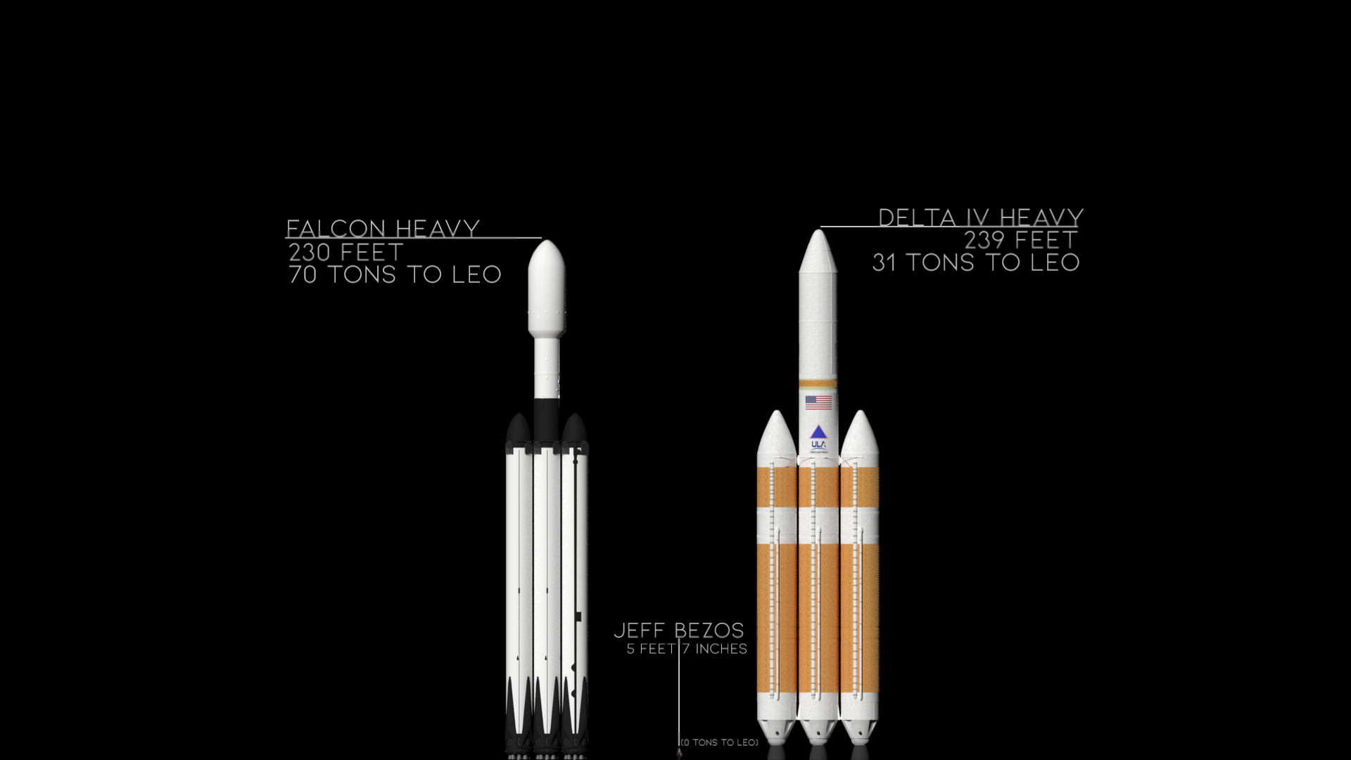
I've started working on a new build at 1/88th scale of the ULA Delta IV that launched the Parker Solar Probe on August 12th, 2018. You can watch the Parker Solar Probe launch here. The Parker Solar Probe is now the fastest human made object ever. This will be a three cluster three stage model rocket.
Here are a couple of cool videos related to this project:
As with my last project the goals of this build are ambitious:
1: 1/88th Scale so BT-70 tubes can be used for the body
2: A working thee cluster rocket with booster separation
3: Hidden fins for the second sage based on Tim's design at Apogee Rockets
4: A working third stage for the Parker Solar Probe
5: No glue, so parts can be replace as needed.
I'm going to use a modified version of my Falcon Heavy to create the Delta IV using the same magnetic booster attachment/separation and rear ejection recovery I've used before. For the second stage, I'm going to use the flip out fins I developed for my F9 project. I've never done three stages before, so I don't know what that is going to look like.
The 3D printing will be done on a Prusa i3 MK3s 3D printer and all of the designs will be created using FreeCAD software.
At first I thought I would be working with BT-60 Tubes as I've done before, but my initial calculations suggest that a BT-70 tube body would be closer to 1/88th scale for the Delta IV & comparable to the SpaceX models I've been building. In short, the Delta IV has a wider body than the Falcon 9 for the same height.
The first problem I've run into is a lack of dimensions for the Delta IV Heavy. From Wikipedia and other sources, I have body tubes about 16.8 feet in diameter and a total rocket height of 236 feet. But no breakdown of sections (unlike a wealth of information for the Falcon 9).
So where can I find reliable measurements of the Delta IV Heavy?
Last edited: