Tractor Helix rocket (front engine rocket that spins) project

The Rocketry Forum

Help Support The Rocketry Forum:

This site may earn a commission from merchant affiliate links, including eBay, Amazon, and others.
Thanks so much for doing this!

You are welcome.

Have my version about ready to go. I put a wrap of carbon fiber around the middle in order to seal a gap between the motor tubes and 3d printed body part.

George, thanks for the tip about thrust rings inside the 18 mm motor tubes. Will do that. Also put some dog barf in as
BigMacDaddy suggested.

I'm thinking the faucet riser is sort of floppy. I hope it doesn't result in too much drag. Would be nice to design some sort of a flap, instead of having to have a tube all the way through. Of course a flap would introduce friction as wel.

IMG_8194.jpgIMG_8193.jpg
 

Attachments

  • IMG_8192.jpg
    IMG_8192.jpg
    49.5 KB · Views: 6
  • IMG_8191.jpg
    IMG_8191.jpg
    56.3 KB · Views: 6
  • IMG_8185.jpg
    IMG_8185.jpg
    169.4 KB · Views: 9
  • IMG_8180.jpg
    IMG_8180.jpg
    104.9 KB · Views: 9
I'm thinking the faucet riser is sort of floppy. I hope it doesn't result in too much drag. Would be nice to design some sort of a flap, instead of having to have a tube all the way through. Of course a flap would introduce friction as wel.

Even if a flap was easy (mounted on the top of the rear ejection plug, and one in the nose cone area), there'd be two problems. One, without a guide, it would be tricky to try to get the top of the rod to go thru the centering rings inside. Rounding the tip fo the rod would help.

Biggest issue, I think, is the shock cord and recovery system getting in the way.

I originally did think of a way that would not require sealing off the rear of the model. For the BT-70 model, to work up an internal system to route each individual ejection charge into an 18mm tube running all the way to the back (so, a pair of 18mm tubes). There would be a chute stored in each 18mm tube. But that would be too much PITA to get into (and extra weight, and probably wearing out after a few ejections). Fortunately, not too long after, the current method came to mind.
 
Last edited:
Got out for a test launch today. 3-motor version took off great, but no chute deployment. My 1st attempt at rear deployment.

2-motor version only one motor fired. Chute deployed, though.

But pretty cool. Didn't take long to spin up really fast.

DSC03539_crop.jpg
 

Attachments

  • DSC03537_cr.jpg
    DSC03537_cr.jpg
    30.8 KB · Views: 7
  • DSC03538_cr.jpg
    DSC03538_cr.jpg
    28.4 KB · Views: 8
  • DSC03568_cr.jpg
    DSC03568_cr.jpg
    44.6 KB · Views: 7
Congratulations, Curtis.

The smoke trail of the 3 engine cluster looks really nice.

As for the misfire, I am now totally "sold" on the BP electric matches by MJG Technologies. Those are what I used for the last flying session (one misfire but it was a wiring hook-up issue that had nothing to do with those BP matches). The only thing I'd trust more would be the old Quest Q2G2's, that are OOP (I used some for two flights before I found out about these)

https://electricmatch.com/rocketry/see/23/6/bp-rocket-starters
I found that I did not have any balsa BT-60 noses, for the upcoming BT-60 model. Fortunately, MASA member Neal Higgins had a couple, I got those from him today while during a shopping trip out his way. I'm going to add a 1/32" ply disc to the base for heatproofing against the ejection charge heat.
 
In my after action report, I think my 2-motor failure was basically due to me being in a hurry. I have had very good success on BP cluster igntion by dipping Estes starters in Quickburst ProCast or QuckDip. On Friday, my launch lead alligator clips are a bit dirty. Usually, I take fresh multistrand wire and wrap it around the starter leads and the alligator clips in order to assure a good connection, but I neglected to do this. Also, they were flapping a bit in the wind and could have shorted.

I am always grateful for BP starter tips, so I will try out the MJG BP electric matches. I'm a fan of their regular electric matches, and they also have a smaller diameter one for those smaller composite motors, which I want to try out. Thanks Geogre for the tip.

The PETG held up fine to the ejection charge heat. I think all the bends and curves slowed down the ejection gasses.

I ordered some new BT-60 tubes from Apogee, which arrived Wed. They seem to be a few thousands bigger than my previous ones. I can't remember where I sourced the first batch from. Maybe Balsa Machining. Or there could simply be variations between tube runs. So George, I hope the jigs that I made for you will fit.
 

Attachments

  • DSC03576_cr.jpg
    DSC03576_cr.jpg
    36.3 KB · Views: 7
I ordered some new BT-60 tubes from Apogee, which arrived Wed. They seem to be a few thousands bigger than my previous ones. I can't remember where I sourced the first batch from. Maybe Balsa Machining. Or there could simply be variations between tube runs. So George, I hope the jigs that I made for you will fit.
I get most of my tubes from BMS, except when I need something more unique that eRockets has (like "Semroc" versions of unique Estes/Centuri tubes, like BT-19). Either way, I'm sure the jig can be used fine, even if I have to add some shimming tape to the mount tubes if the jig halves are slightly apart, or whatever. The hole marking jig, if it won't slide on, I can split it and use tape to make sure the two joints are the same distance apart. But hopefully you had BMS tubes before.
 
Last edited:
I've gone crazy making these. My latest is a 4-motor, 35 degree can, 10 degree skew.

So I have the marking guide. First, mark the holes, and then cut the motor tube holes.

Then the inside collar will be glued on the inside.

Finally, the outer jig will hold the tube in place while the glue dries.

George, I think the glue jig will work better cut horizontally, rather than vertical. That way there won't be multiple segments to hold in place.

IMG_8265.jpgIMG_8262.jpg
 

Attachments

  • IMG_8261.jpg
    IMG_8261.jpg
    128.3 KB · Views: 3
  • IMG_8251.jpg
    IMG_8251.jpg
    118.4 KB · Views: 3
At the MASA launch Sunday, I made two flights of the Tractor Helix rocket. Flight 1 went very well.

YLcRw4Q.jpg


Flight 2 got off to a poor start. I was using chewing gum to hold the electric match wires in the nozzles. Normally I use clay or putty but it was too cold to stick (can't use tape, the electric match wires need to let go easily. And Estes ignitor plugs won't fit with the thicker wires). On flight 2, I happened to have the wires pressed to one side, of each nozzle, that ended up causing the gum to lift to one side at ignition, which vented thrust sideways, which caused it to start to roll the opposite way from normal. As it started up the rod, the nozzles cleared, and it the normal thrustline torque caused the wrong spin to stop. The roll had stopped when it left the rod, and unequal thrust (two different brands of C6's) caused it to tip to one side due to no roll to even it out. Once it left the rod it started to roll the normal way and did not curve any more, a slanted boost.

From now on, I'll make sure that the gum or clay is pressed the other direction, to help the correct roll to start at ignition (As I think happened on flight #1). This is one of the big benefits of having an at-pad-camera with that view, to see what really happened when something odd occurs that is not noticeable real-time from a distance.

8QXhnrW.jpg


Also, the tail plug had felt a bit tight, so I removed a piece of tape. Well, it ended up a bit too loose, falling out during the boost, causing the parachute to deploy early from the back. But it landed safely.

 
Would a ring fin be an improvement? I think it woul keep the CP back there without resisting the spin.
 
Hold your igniters in place with 1/4" masking Tape... They will stay put and the tape will rip easily. This method is tried and true.

Note: burned put motor for example... I don't put igniters in place indoors... Like the guy who had an I65 ignite in his hotel room in Indiana years ago...

1646093375268.jpeg
 
Hold your igniters in place with 1/4" masking Tape... They will stay put and the tape will rip easily. This method is tried and true.
See message #3 for this thread. https://www.rocketryforum.com/threa...rocket-that-spins-project.169137/post-2196985

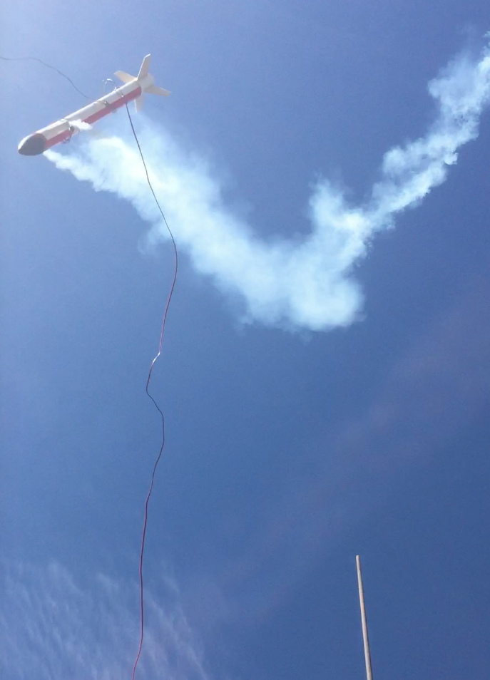
Tangled the ignition leads, that got wrapped up around the body.

8d8Z4dg.jpg


That was the last time I used any tape. This model is very unique. I needs for the ignitor to leave the engine as soon as possible, gently, with no yanking.

The putty/clay/gum (when cold) method works pretty well for that. The drawback is that effect I described, which now that I'm aware of it, I can actually use as an advantage, by pressing the wiring the other way, to cause the ignition side-thrust to help start the spinning sooner than normal.

Funkworks, a ring fin for stability and minimal effect on roll is a nice idea. It still would have to be mounted by some stub-fins, though those would have a lot less area, so far less of an effect on "roll drag". A cardboard tube would have a problem of squashing out-of-round when laying on its side, and this model is so big I do not even have a box for it, I just lay it in the car on top of other stuff. A ring out of plastic could solve a bit of that, though still an issue, then adding some problems of adequately glueing strongly enough. For the physics of spinning I like that idea. Though for the aesthetics, I've not cared too much for that design approach.

A way to address the roll drag would be to either cant the fins a few degrees in the direction of the spin, or to do it more simply by gluing the fins straight but adding spin tabs.

But I like the spin rate this has, at least when flown single stage. Since when staging, it does have a problem of the spin slowing down, that would be the biggest reason to cant the fins or add spin tabs.
 
I am writing up a report about this project. I am referencing some models I know of from the past, which had elements of this method, such as non-spinning tractor models.

There is a photo I can recall, from the 1980's or so, of a model that had canted engines MID-WAY up the body. So if it had a 36" tube, the canted engines were at about 18". But I thik it was a longer model than that. IIRC it was a homebuilt model, not a kit.

If that rings a bell, please provide a link to a photo of it or other info.
 
Well, I forgot to post this video that I used for my R&D presentation at NARAM until now.

Yes, R&D. Took second place for or our Neutron Fusion Team in "D" (Team) Division. Not bad for what I refer to as a "third place report", when we do not have a top-notch project that would be likely to win. OK, so there were only 3 Team R&D entries..... :)

The first few minutes I talked & showed the model, then ran this video and did live commentary as it played on a projection screen. Then when it ended I talked for another minute or so (10 minute presentation).


I made two flights of it Friday at NARAM-63, during Scale. Photos by Tom Beach.

Nbhl30s.jpg


Launch 1

py6ThLX.jpg


Coming down under the chute.

yekD25T.jpg


Well, note that originally I had a drogue chute too. Well, that drogue lost a lot of lines and I stopped using it, and did not have a spare. I should have made a new drogue, but kept rolling the dice. On the second flight, #13, it boosted very well. But the main chute never came out, so it crashed very hard. Nose section destroyed, skewed mounts ripped out.

Boost of the second flight (#13). I did not take any "after" photos.

16Alohq.jpg


I do still plan to build a BT-60 version.

.
 
Last edited:
Back
Top