Tractor Helix rocket (front engine rocket that spins) project

The Rocketry Forum

Help Support The Rocketry Forum:

This site may earn a commission from merchant affiliate links, including eBay, Amazon, and others.
Inspired by the wondferul notes and lessons learned here, I am trying my hand at this. 15 degree cant angle and 10 degree offset for spin. Using two motors and rear ejection.

I'm printing a 3d motor mount. I will fit BT-20 tubes in the 3d printed part, which goes into a BT-70 body tube. The PETG has a baffle to direct the ejection charge backwards. It will probably melt after about 5 launches, but I'm just experimenting at this point.

I designed two motor and three motor versions but will try the 2-motor one first.

BT-70 seems like a nice size for this

@georgegassaway thanks for the build log. Your cant angle seems a bit bit, but OMG, how impressive when it works.

1638117346016.png
1638117391331.png
Bottom pix shows a cut away

1638117549983.png
 
Flew the Tractor Helix rocket a few more times at the Nov 20th MASA launch.

Y1n9nP5.jpg


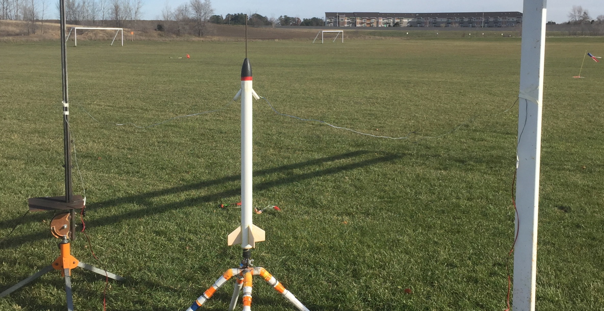
Due to the club’s set-up at the field, one of the side umbilical posts I used was a soccer goal. The other was a pad with a rail when nobody else needed to use it. I had a couple of long rods to stick into the ground, but those were more convenient and secure.

PR8UjMn.jpg


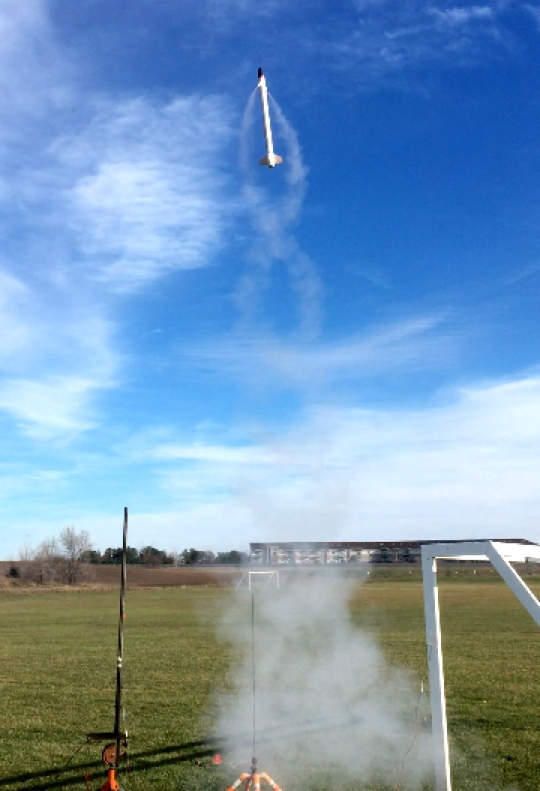
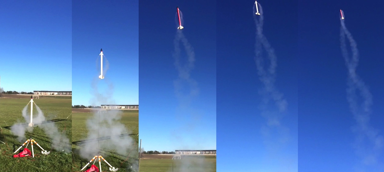
Flight one went very well, mostly vertical, in wind of 7-9 mph.
qhIvOTE.jpg


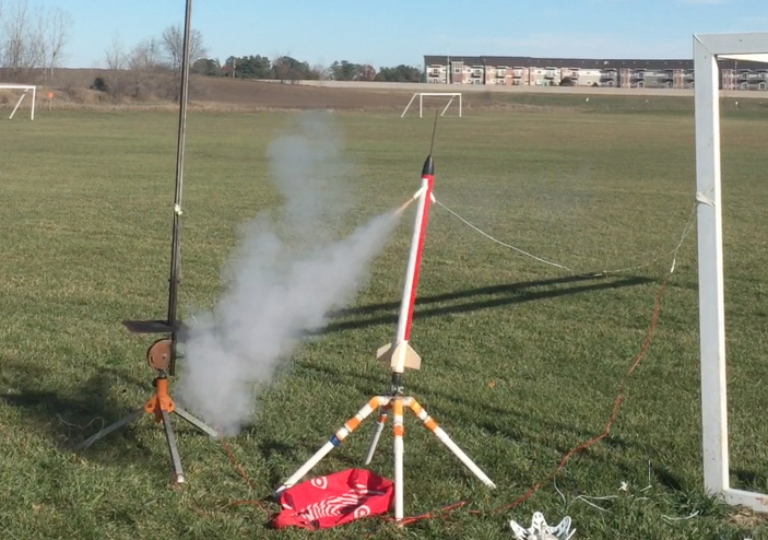
Flight two was Chad-staged, using a C6-0 taped securely (Scotch tape) to the upper C6-3, in each mount.
vvQN5CO.jpg


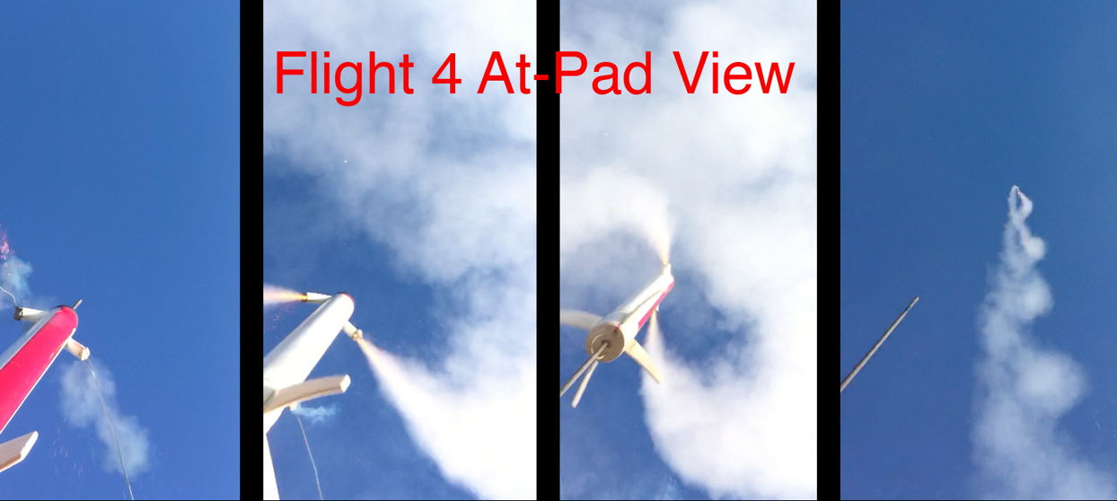
It took off and weathercocked some. It is more nose heavy with two extra engines up front, so that may account for a good bit of that. Anyway, also, at staging it “veered” a bit, to make it get even more horizontal. Later, I saw from the at-pad-looking-up video, that one engine staged 7 frames before the other engine (that’s about 1/4 second difference, which is a pretty big mismatch for the high thrust spike of the engine that staged first). So, it may have by coincidence pitched more horizontal due to the direction it was rolled (meaning, if the opposing engine 180 degrees away had staged first, it might have actually veered a bit back towards vertical).
KeasKX6.jpg


And definitely it stopped rolling during the second stage burn. Not only does the smoke trail stop being a helix, but the pulsating thrust sound goes away into a constant “normal” thrust sound at high altitude. Weird. The same had been noticed on the previous CHAD-staged flight, but the at-pad camera did not show that as clearly (both staging “puff” moments) as with today’s flight 2.

Fortunately, it ejected before hitting the ground, landing far away mostly upwind. Definitely if I stage it again as-is, it will need to be pretty calm. Or else do the C6-0 to C6-0 (with BP charge) trick. If I really want for it to keep rolling when CHAD staged, I’d add some spin tabs to the fins.


Flight three…..actually didn’t happen but I call it that anyway. Only one engine lit, and…….it stayed on the pad. That was a good surprise, that it didn’t get into the air, so no damage. It was not the ignitor’s fault, it was a clip whip not making the proper electrical connection to set it off, I did not double-check it as I should have.
r4SL4yA.jpg


Flight 4, one of the e-match ignitors was the same one that did not fire before, because it was not at fault. Single stage, two C6-3's. Ignition was great, and it took off very well for a mostly vertical flight, best so far.
MML7rMy.jpg


JOym4m5.jpg


The chutes have gotten worn out (Main chute lost half its lines even though it’s a reinforced over-the-top type chute. Just….old and worn out. Like, one is 10-15 years old, and I borrowed the 12” chute from a model built in the early 1990’s). So I need to make new ones before it flies again. And the next club launch won’t be till late January. Do not say nylon/cloth chutes, the chute packing space is way too limited due to the axial lug running thru it.

These flights were my first time using e-Matches that fit model rocket nozzles, from MJG Technologies (they say they fit in 13mm BP engines like 1/2A3, have not tried yet). They worked great for this model, so no more using precious OOP Q2G2 ignitors. They come in 12” & 36” lengths, for 3 cents more I went for 36” since this model can make good use of that length for the twin umbilicals so far apart. https://electricmatch.com/roc.../see/23/6/bp-rocket-starters.


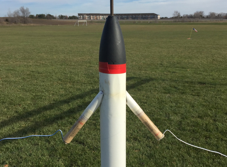
To help make sure of a “clean” separation of the e-Matches when the engines ignited, I could not use tape to help hold them (that was the prime cause of taking up the leads a few weeks ago). So, I used a window putty sort of like modeling clay, but it does not melt in sunlight in summer. On a cold day like this, it is stiff and did not stick to the nozzles too well, but I managed to get it to work out. Though one time, the wind eventually caused one to wiggle out.

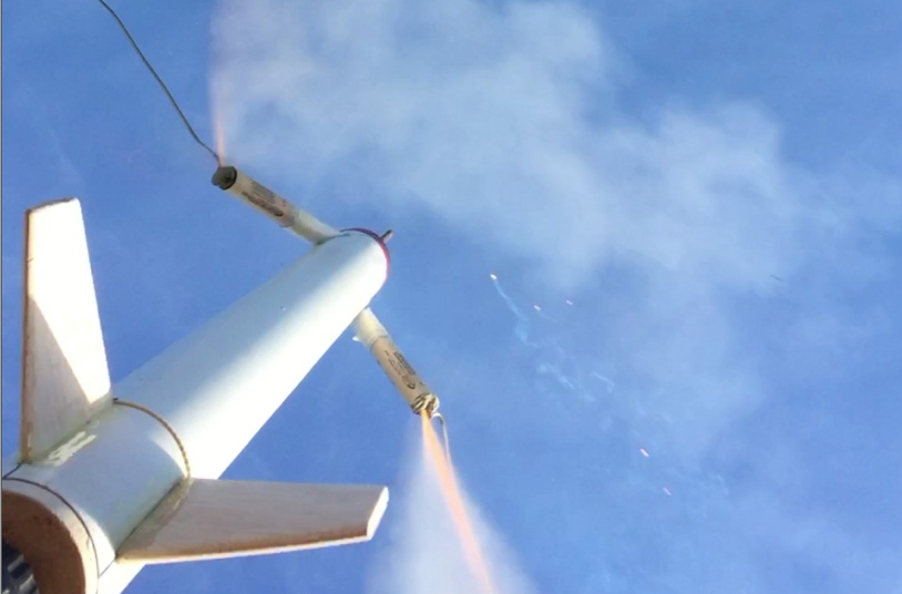
I was surprised to see in slo-mo of the at-pad video for flight 2, Chad-staged, that the model started to rotate the opposite of normal, as the motors began to ignite. Then I realized the putty plugs were causing exhaust to vector a bit sideways for a moment, and the CHAD staged nozzle distance gave extra leverage to cause the roll the opposite way for a moment. But that had no effect on flight, the model was rolling the other (normal) way before it moved much up the rod. The screenshot below, you can see the moment of ignition, with exhaust being momentarily deflected by the putty (note the sideways engine exhaust at upper left, and non-parallel flame at lower right).
RkmgooJ.jpg

Yet again, the odd stuff you sometimes see with an at-pad camera view like that.

I had tack-glued the axial lug assembly in, and it has come loose, sliding out at ejection (the two 1/2” vent holes are not big enough. I kept sliding it back into place. And the fit with the nose cone’s sleeve tubing (Tube #3) is not good anymore. So I need to do some overhauling of that lug system. What I really wish I had was a stiff fiberglass tube (more like arrowshaft or kite spar, not rocket tube), that was a bit more than .25” I.D, and some sleeve tubing to fit over it, rather than the paper tubes I have been using. But shipping is cost-prohibitive to order just a couple of such things (No, Amazon, I do not need to buy 12 arrowshafts for $49 with free shipping, even if the I.D. was right. Or buy one from elsewhere for $15 shipping).

I’m really happy with how well this model flies.

So, yes, of course there is video.

The coolness factor of this build is way up there. Love the visual of the twin spiral exhaust trails, and the sound it makes as it spins up even more.
 
Inspired by the wondferul notes and lessons learned here, I am trying my hand at this. 15 degree cant angle and 10 degree offset for spin. Using two motors and rear ejection.

I'm printing a 3d motor mount. I will fit BT-20 tubes in the 3d printed part, which goes into a BT-70 body tube. The PETG has a baffle to direct the ejection charge backwards. It will probably melt after about 5 launches, but I'm just experimenting at this point.

I designed two motor and three motor versions but will try the 2-motor one first.

BT-70 seems like a nice size for this

@georgegassaway thanks for the build log. Your cant angle seems a bit bit, but OMG, how impressive when it works.
Yeah, the model I made is BT-70. I'm trying to work out how to do it smaller/lighter, with BT-60.

If I had the skills to do up 3D parts, I'd do it as a couple of jigs to specify the outward cant angle and skew angle for spin. One 3D part would be a collar to slide on, that would have openings to trace by pencil to mark where to cut the complex curves for the engine mount tubes to go thru. (I need to take a photo of the tool I made up to help me. On break at work right now so can't).

The other would be a removable external jig, secured to the main body, but also holding the engine tube in place, during the process of gluing the mount in. I know there is a slight mismatch on the model I built, but figured the spin would even things out.

So, there was a two engine spinning tractor rocket that planted the seed for this. After the Challenger accident, NASA considered the system below, to pull a crew member out one by one, if the orbiter could not land safely (over ocean for example). I do remember seeing video of some testing, but cannot find it now.

PWsoDKC.jpg


Instead, NASA went with a deployable curved pole, that a crew member would snap a clip to, and in going out the hatch, the curved pole would direct them down and away from hitting the left wing.

But I did re-find a video I saw 1-2 years ago. The "Yankee Escape System". Using a twin-nozzle fast spinning rocket motor to "yank" a pilot out of a plane, instead of an ejection seat. This was done in the mid 1960's, and it seems like what NASA tested for the shuttle was at least based on this concept, if not the same company.

 
OK, so here is a composite image showing several views of what I used to determine the shape of the holes to cut into the BT-70, for the 18mm engine mount tubes to fit. I used an 18mm balsa coupler, cut at the cant angle I wanted. Put 240 grit or so sandpaper on the BT-70, and sanded it to get a curve into the balsa. Also, I held it at a skew angle as I sanded up and down along the tube. Sort of hard to see the concave surface in the two lower pics, but I tried. In the upper two pics, I just have it laying on top fo the tube for the pics, it's not glued.

WBCWkU5.jpg


That was used to trace the complex ovalish shape onto the tube, 180 degrees apart. I did end up with more total outward cant than I had intended, not entirely due to the original diagonal cut, but also that skew angle added even more to the combined cant angle. Although, while I had intended for less of a cant angle (less thrust loss to cosine angle), I will say it does add to the helical smoke pattern being wider than it would have been if it was canted less.
 
Yeah, the model I made is BT-70. I'm trying to work out how to do it smaller/lighter, with BT-60.
'''
The other would be a removable external jig, secured to the main body, but also holding the engine tube in place, during the process of gluing the mount in. I know there is a slight mismatch on the model I built, but figured the spin would even things out.

I can whip this one up in a jiffy for you. BT-60. What angle and skew do you want?

George, thanks for the historical reference. That's very interesting.
 
Last edited:
Reworked the MM. BT-60. 25 degree cant, 20 degree skew.

A faucet riser from HD will make a nice tube down the center for the launch rail.

Will re-work this tonight and print for a jig for George, based on the params he wants.


1638277264453.png
1638277283783.png
1638277300296.png
1638277309857.png
1638277414166.png
 
Wow, those parts look really nice!

Sorry I did not get back to you before on your offer to make a 3D mount. I was doing a lot of thinking.

With the current model, I really like the ability to remove the nose cone to access inside the mount area. That is why I use vinyl tape to hold the nose on.

I found that the inner layer of the paper tubing gets roasted by the ejection charge aimed right at the inner wall like that. I have added some aluminum tape to help take the brunt of it, need to open it up and replace that aluminum tape. If I had thought of this issue during the build, I would have added a section of coupler tubing in the area , and coated the inside of that with thin epoxy to try to prevent charring.

I think ejection heat damage is going to be a major problem with the 3D parts, you estimated replacing after 5 flights, but they may be “toast” after one flight.

For the BT-60 version you are offering to do for me,I’d like to be able to put a cardboard tube liner inside, to protect the 3D part, and I’d also give a coat of tin epoxy to the cardboard tube inside (using the 3D part to mark the holes and cut out by knife, a bit oversize, to fill in gaps with epoxy).

I was thinking perhaps BT-55 liner, but looking at parts fit and such it would be better if the cardboard tube OD was bigger. I see your engine mount part is are very thick like 3/16” to 1/4”?). I figure you can alter it to be thinner. I know that being thick it helps to align the engine mount tubes better, but to me the key is have the hole shape correct, and I could do some things to try to be sure the engine tubes do not “wiggle” during gluing, to maintain the desired angles (Or, rather than just holes, add a bit of external hood sticking out). I do not even want to specify a diameter for the cardboard sleeve tube to fit inside of, as I realize even BT-55 leaves less room inside than I would like, thinner is better. So whatever the 3D mount inside diameter ends up being, I can custom cut a BT-60, cutting out a gap, to custom fit the inside diameter of the 3D part (I have made BT-60 tube couplers this way, cutting a gap out of BT-60 and using the cut out gap strip as a lengthwise joiner strip).

As I said before, it is nice to be able to access the inside, from the top. So if you make one for me, it would be good for the 3D part ot have a coupler at both ends. Not just the bottom but the top too. So there could be a short section of BT-60 tubing between the 3D mount and the balsa nose cone (I’ll be adding a 1/32” plywood disc to the BT-60 version, as heat protection, and probably add some epoxy protection if not something else more durable. Perhaps two layers of 1/32” ply).

You mentioned a faucet riser for the lug tube, and now I see that in a photo. I like for the lug tube to be straight to begin with. I figure the launch rod will straighten it out for yours, with a bit of sliding friction. Certainly with your BT-60 version being lighter, and less of a cant angle, you’ll have more thrust to weight ratio to get it going. I am concerned that EJ heat will melt it, you meed some sort of heat protection near the upper area.

I have a three foot piece of 5/16” aluminum tube from K&S, 36” long (9/32” ID, so 1/32” clearance for a 1/4” rod). I was going to use that on the first model, but could not find any 11/16” tubing in my collection of K&S tubes. So, yesterday I went to a hobby shop to get 11/32” tubing to use for the short piece for the tail plug, and longer piece for the nose cone (so I can remove the nose at any time, taped on with vinyl tape). Actually, they had 36” long 5/16” aluminum tube too, so I got another one as issues have developed with the axial lug tubes in the original model, so I plan to remove the whole axial lug assembly that has the three tube diameters and replace with 5/16” aluminum tubing.

As for the cant angle and skew angle for BT-60…… roll-wise the problem with going from BT-70 to BT-60 is that the engine casings (thrustline) will tend to be not be spaced as far out, so less leverage, less roll torque. Although originally I imagined a slower roll….. now that I’ve flown it, I like the fast roll.

Anyway, the “cant” angle I’d like should be zero (“huh”? :) ). And the “skew” angle to be 35-40 degrees (I need to try to measure the effective combined cant/skew angle of the original model). OK, I checked Apollo data and see that the LES abort nozzles were canted at 35 degrees, so I’ll go with 35.

Below is a composite photo showing a very crude example of what I mean by zero cant and 35 degree skew for roll.

Bd826Kx.jpg


I used some wooden sticks as a spacer and just have the engine casings sitting in place. I definitely want for the top of the engine mount tubes to be totally inside of the cardboard liner tube I refer to, so the engine casings may need to be closer together than shown by the wood spacers. Indeed it might require not having any space at all between the mount tubes. So what about the rod and the lug in the center? Well, easy, the top of the mount tubes will be cut short , leaving plenty of room for the lug in the center.

One thing occurred to me about the BT-60 model. I’ve planned to use a 34” tube. But it occurred to me later that I could make it 10-12” longer, and not need to have a hole thru the nose cone at all. Just plug the top of the 5/16” aluminum lug to keep the EJ from leaking thru, and have the 48” rod inside the model (about 2” is lost from the pad mount at the bottom). I still might just go with 34” tube, as that is easier to transport. Of course I could also just plug the top anyway and have the model just sit 10-12” up on the 48” rod. But it’ll get a better launch with a longer rod. And it certainly looks different to have a model sitting on the pad….. with the rod coming out of the nose cone.
 
George. Thanks for your thoughts.

I was going to try to make a design for me with the motor mount 3d printed, I can certainly additionally make a jig.

The jig would look something like this, and I realize the marking and gluing ones need to be separate (or the latter would be unremovable!). One would be for marking. Then I would print it in two halves to be used for gluing.

I would see "cant angle" as the side to side from the vertical axis, and skew as the angle that gives the roll. So I think we are using them backward, but that is not too big a deal as long as we understand each other (So 35 cant and zero skew).

My day job is calling, but I'll digest the rest of your email tonight and get back with you.


1638794597419.png1638794630334.png1638794652606.png
 
Curtis, thanks for your help.

(I wrote some of the text below before seeing your post today. I did not realize that for me you were thinking jig anyway)

I have an idea for how a 3D jig could be done, not using as much filiament and less print time.

Think of a collar to fit around the outside of the BT-60, thick enough to align the mount tubes well (and the inside of the holes being traced out to cut out the area of the BT-60 for the mount tubes to go.

But not a 360 degree collar. Only a 90 degree collar, with the tube marked like you would for 4 fins, but in this case the 90 degree marks that the sides of the 90 degree collar would be aligned with, and taped to the outside of the tube (also upper and lower horizontal lines around the tube to define the top and bottom of the 90 degree collar location). But I do not think it would be practical to remove the collar after gluing a mount in place.

So, to have the 90 degree collar split parallel along the 35 degree “skew” angle for the engine mounts. The 2-piece collar would be taped along the 35 degree skew break lines, used like it was one piece. Then after tack-gluing a mount tube in, all the tape removed and the jig collar removed in 2 pieces.

I am very concerned about heat protection in that tricky area, and the need to force the engines closer to the middle due to the internal thickness, and being heavier with a 3D part. By using a jig, the heat protection I can add to the ejection area, before gluing, could simply be a BT-60 tube coupler.

I modified photos as shown below to crudely indicate the 90 degree collar, and 35 degree skew split line.

ZgzLcJh.jpg


However, after seeing that, perhaps a 90 degrees arc may not be sufficient. So perhaps a 120 degree arc for the collar, and I’d mark the tube alignment lines like for a 6 fin rocket.

For whatever reason, I was thinking that a 2-piece jig split horizontally might not allow the jig to be removed after the mounts were glued in. But seeing your images above, a horizontal split probably would work (I note that the part you show looks like it has all cant and no skew, rather than 35 degree skew & no cant).

After seeing your post above, well, certainly a 360 degree collar would be better, and a thin walled marking guide to make the lines a bit more accurately. I was just thinking of reducing the amount of stuff you need ot do to draw them up and print them (OK, so it may be easier to draw a 360 degree collar than to chop it up into a 120 degree arc).
 
George, this relatively small part, so the amount of filament is small. I think 90, 120 or 180 degree wrap around is in the noise.

I do see your point that a vertical split might be better than a horizontal split. Here is what the glue jig would look like, although I would extrude out the other side (need to run).

1638823272221.png
 
George, thanks for all your thoughts and good ideas. Has my head spinning (pardon the pun) in a good kind of way.

Additionally, since you are building Apollo LES abort nozzle, I designed a 3 motor version. I find the CAD design very zen and relaxing, so I love cranking these things out. A few clicks and sort of something from nothing.

Will print some of these up this weekend and check for tolerances. May take a couple of tries to get the slip fit correct.


1638883151478.png
1638883164814.png
1638883181003.png
 
Interesting design and some great 3D design skills...

In my experience printing with ABS there is no need to use motor tubes (although I have not launched any of my rockets w/ 3D printed parts a dozen times or anything). If you design the 3D printed motor mount with an integrated block you can easily keep your motors from moving up too far, etc... I have not used PETG.

I also think that you could leave a bit more of a compartment / space for the ejection charge to go into so that the pressure would exit out the rear with less likelihood of melting the parts. This could even give you a bit of space to put some dog barf which would / could? reduce the melting while allowing pressure to still eject our rear tubes.

I have also had good luck with making twist lock parts. This could provide a way to have a replacement top that would screw and lock onto the top of the engine mount and can also allow you to include both motor blocks and retainers in your parts.

Not sure if this is easy to see here but this is the design I did for the Tao rocket. The engines are loaded from the top and then the engine block (the disk in the middle is shaped to slip onto top of angled motors below) is placed on top of the engines and twist locked into the compartment / lid (this was designed to give a bit of space for ejection charges to dissipate and eject gases out of the empty motor mounts -- I was only planning to use 4 of 8 mounts so gas could eject out of empty bays). This had a BT50 tube that inserted through the whole thing which is not necessary in your design obviously. You could do something similar to make your engine block and dissipation / redirection chamber replaceable with a simpler locking mechanism in the nose cone or top tube section.

Edit: Glad I posted since I realized I had recombined parts incorrectly on the latest digital version of the Tao and cut out some critical internal parts.

1638971052999.png
 
Last edited:
Great ideas. Thanks for sharing. The locking parts is something I will have to work up to.
Started printing parts for fit check. Got the BT-60 diameter a bit off and will have to tweak and redo.

And to be clear. This is the positioning jig for gluing the motor tubes in place

1EB353E1-620D-485C-B870-C93C22FEFB30.jpegF236D03F-7937-4A2D-B55A-2DA09193B8D5.jpeg
 
Last edited:
My 3rd photo didn’t post. Small bit of play around tube. A few pieces of blue tape would probably suffice, but better to get it right.FE055130-645B-4560-970D-31C555BAF9A3.jpeg
 
And to be clear. This is the positioning jig for gluing the motor tubes in place
View attachment 493149
That looks very nice for a jig to a non-spinning tractor.

But if that is for me, the cant needs to be zero and the skew 35, with the top fo the engine tube barely inside the edge of the tube, like this crude example:
Bd826Kx.jpg


Also, BigMacDaddy, look at how the skewed angle causes the ejection charges to be aimed inside the tube. I've had major ejection burn damage to the BT-70 tube of my prototype. This is is totally unlike a normal "straight up the tube" ejection charge heat damage issue.
 
Last edited:
So for George, I have 1) a cutting template. Slide over BT-60 tube, mark, remove, cut.

2) positioning jig. Put jig in place. Slide motor tubes to desired depth. Glue. Dry. Remove jig.F5B12364-E165-48E2-AA8E-41D08FD552D8.jpegE8097C28-1A86-4207-BA66-F6348B807B95.jpeg

3) (optional). A thin collar to be used with 2 that fits inside of tube. Maybe just glue it in place. Which I haven’t printed yet. And I need to reprint (2).
 
2) positioning jig. Put jig in place. Slide motor tubes to desired depth. Glue. Dry. Remove jig.View attachment 493189
I really appreciate the work you are doing. But the above looks like cant of 35 and skew of zero, not cant of zero and skew of 35 (Maybe I confused things using those terms?). The model would not roll at all due to thrust.

The mount tubes ought to be aligned such that in an end view, the mount tubes would not even touch each other if they extended all the way inside of the tube. Compare with the pic in message #50.
 
That looks very nice for a jig to a non-spinning tractor.

But if that is for me, the cant needs to be zero and the skew 35, with the top fo the engine tube barely inside the edge of the tube, like this crude example:
Bd826Kx.jpg


Also, BigMacDaddy, look at how the skewed angle causes the ejection charges to be aimed inside the tube. I've had major ejection burn damage to the BT-70 tube of my prototype. This is is totally unlike a normal "straight up the tube" ejection charge heat damage issue.
FIRE AND BRIMSTONE...A WRATHFUL ROCKET GOD! Adding a dolup of epoxy to create a plugged motor will only lead to the Dark Side.
A gas piston deploying retarded bomb fins for a helicopter recovery would be cool. Or gas ejecting a side chute would be awesome. Gives me a Garand ejecting out the strip clip kind of feeling.
 
Last edited:
A pop wing, Dune style Ornithopter with glide recovery would be cool.

A spinning tape worm rocket would be very popular at the RSO table! A cant angle too far.
IMG_20140719_143256910.jpg
Tractor Motors Rule! Too much oddroc fun!
 
Ah. George, you want the thrust lines offset. Sorry, slow on the uptake. I’ll rework. No worry

Edited.

Like this. Here is the start

1639096940172.png

1639096975016.png
 
Last edited:
FIRE AND BRIMSTONE...A WRATHFUL ROCKET GOD! Adding a dolup of epoxy to create a plugged motor will only lead to the Dark Side.
A gas piston deploying retarded bomb fins for a helicopter recovery would be cool. Or gas ejecting a side chute would be awesome. Gives me a Garand ejecting out the strip clip kind of feeling.
Hmm, if I knew what you were taking, would I want to try it or not? :)

BTW - your comment of what would be cool, reminds me of when I made my scale R/C X-1 rocket glider: "What would be really neat would be if it deployed landing gear". Or my space shuttle with SRB's that automatically sep 1/2 second after burnout (wind-up timers deploying chutes), RC sep of orbiter from ET (onboard computer ejecting chutes for the ET), and orbiter gliding down by RC: "But what would be really neat would be if it had tiles and deployed anding gear". And my 1/16 Lunar Module Quadcopter: "But what would be really neat would be if the Ascent Stage took off after landing". As though those models were not "neat enough".

My standard reply to such things now is "I look forward to seeing your model that [does whatever "really neat" stuff they thought was needed]."

This model is cool enough. If someone wants to see something more, I look forward to seeing them fly theirs. :)

And the jig would look like this:

View attachment 493383
Ah, yes, that looks NICE.
 
Last edited:
I think I have got it

- Cutting guide. Slips on outside of BT-60 rocket

- Gluing jig in two halves. The jig halves fit tightly together, but I can't do that and take the picture (not enough hands)

- Optional inner positioning collar. Glue inside BT-60 tube. The advantage of using it is that it has a "stop" to make sure motors are inserted to same depth.

George, PM me your address. I will mail them Mon. The only thing I ask for in return is feedback in the design.

Edges will need a bit of sanding

IMG_8169.jpgIMG_8164.jpg
 

Attachments

  • IMG_8161.jpg
    IMG_8161.jpg
    53.1 KB · Views: 4
  • IMG_8160.jpg
    IMG_8160.jpg
    59 KB · Views: 3
  • IMG_8142.jpg
    IMG_8142.jpg
    70.2 KB · Views: 3
That looks GREAT!

I can just mark the distance on the lower end of the mount tubes, to stop at the lower end of the jig (after I’ve test fitted the mount tubes to see how far to go inside). That is what I did with the original.

Also, in order to allow clearance for the launch lug in the center, and to allow the ejection charge to expand outward as soon as possible, I’m going to sort of diagonally trim the top ends of the mount tubes. Most likely use the BT-60 marking jig to also mark the upper end of the mount tubes (will make the mount tubes longer to allow for the trimming).

BTW - to consider for your own model, inside the 18mm mount tubes, I’ll be using 18mm coupler tubing not only as a thrust ring, but also to provide an extra layer of heat protection from repeated ejection charges. I did that with the prototype too.

PM’ed my address.

Thanks so much for doing this!
 
Back
Top