SSRS Lasor Series

The Rocketry Forum

Help Support The Rocketry Forum:

This site may earn a commission from merchant affiliate links, including eBay, Amazon, and others.

MarkII

Well-Known Member
Joined
Jan 18, 2009
Messages
8,250
Reaction score
46
Anyone remember this minimum-diameter mid-power rockets from the 1980s?

Like many other rocketry-related things from the past three decades, I learned about these rockets and the company when I saw one of the company's (by then rechristened as Crown Rocket Technology) catalogs on Ninfinger.

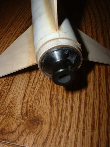
I was immediately taken with the Lasor Series. SSRS/Crown thoughtfully included pretty complete dimensional information for their components and models in their catalog, so the Lasors looked like they would be easy to clone. Semroc had compatible parts.

There are no plans or assembly instructions for any of Lasors on any of the usual online sites, but I did find Steve Naquin's RockSim file for the Lasor 114 on the rocketreviews.com website. Steve's clone design deviates from the original Lasor 114 in a few ways. He identifies some of them, and i deduced others by comparing his components and dimensions with those listed in the catalog. His design was especially invaluable in providing me with a template for the fins.

Thanks to Steve, I have a fairly firm idea of the design of the Lasor 114. Other than the information provided in the catalog, I don't have any information for the other two models in the series, the Lasor 95 and the Lasor 134. I tweaked Steve's RockSim file to make it more closely agree with the catalog information (using Semroc parts). Then in order to create the other two, I used part dimensions from the catalog and scaled Steve's fin templates accordingly. I have no idea if this accurately represents the 95 and the 134, but it seemed like a reasonable assumption and it worked for my purposes.

Here is my basic Rocksim design file for my Lasor 114 clone.

SSRS Lasor 114 balsa nc 2.jpg

View attachment SSRS Lasor 114 balsa nc.rkt
 
Last edited:
For my Lasor 114 clone, I used:

  • Semroc BC-11549 ogive balsa nose cone - 4.9"
  • Semroc LT-11530 heavy-walled spiral-wound airframe tubing - 30"
  • Hardwood (poplar) dowel payload coupler - 1.125" x 3"
  • Aircraft plywood fins - 1/16"
  • Launch lugs - 1/4" x 1" (2)
  • Couple of thick wire screw eyes
The Lasor 114 is a 29mm minimum diameter design, so construction of it was pretty simple. I started by brushing a heavy coat of Minwax Wood Hardener onto the nose cone. I gave it a couple of days to dry (this was last summer), and then gave it a moderate sanding, and then brushed on another coat of wood hardener. Then I set it aside to dry and planned to return to it no earlier than a couple of weeks from then.

Using a 1.125" dowel for internal support, I neatly cut off 6" from the 30" length of Series 115 tubing. I cleaned up the cut ends of both pieces of tubing with sandpaper, and then turned them around so that the two clean factory cut ends would butt together at the payload section-airframe joint.

I used my Japanese-style dowel pull saw to trim a 3" section from the 1.125" dowel. I inserted and glued 1.5" of it into the clean factory cut end of the 6" section of LT-115 using 30 minute epoxy. I turned a thick-wire, small-diameter screw eye into the free end of this coupler, withdrew it, dropped more 30 minute epoxy into the hole and then screwed the eye back in. I covered the surrounding face of the coupler with more epoxy. Once all of the epoxy had cured I used my fingers to smear several applications of Titebond II wood glue onto the exposed end of the coupler. After that glue had dried I sanded the coupler smooth and insured that it had a good fit into the remaining airframe tube without excessive binding.

(Note: the nose also has a coat of white primer in this photo.)

DSCF0909-2.jpg


DSCF0907-1.JPG
 
I used the attached fin template, derived from Steve Naquin's Lasor 114 RockSim file, to trace out three fins onto 1/16" aircraft plywood. I cut them out using a utility knife with a new blade and a steel ruler as a straightedge. I match-sanded the three fins to even them all up and to clean up the edges, and then I sanded them smooth with my block sander.

Since the Lasor 114 is a minimum diameter design, there is no built-in positive motor retention. I created a wrap-around fin marking guide using the online tool at PayloadBay.com and used it to mark the cut end of the 24" length of LT-115 for three fins. Then I cut a 1/4" wide strip out of some cardstock, wrapped it around the very end of the tube and drew a line around the tube, 1/4" from the end.

I bonded the three fins onto the tube so that the aft end of the fin roots were even with this 1/4" line. Then I used a homemade foam core fin alignment guide to hold the fins in the correct alignment until the glue dried. After they had dried, I used a glue syringe to apply fillets of Titebond II. After the first set of fillets dried, I applied a second set. After all of those fillets had completely dried, I applied a final set of fillets, once joint at a time, using plain Aeropoxy 6209 Structural epoxy. Immediately after applying the fillet, I smoothed it with a gloved fingertip dipped in isopropyl alcohol.

By working on just one fillet at a time and carefully smoothing the epoxy after applying it, I was able to obtain smooth, even fillets without the need for any sanding. No sanding was done on the fillets that you see in the photos below.

The fins are very stiff and very securely bonded to the airframe. The small gap between the fin roots and the aft end of the airframe provides space for a wrap or two of tape around the joint between the airframe and the thrust rings of the single use 29mm motors that I plan on using in the rocket. This will supplement the friction fit of the motor for purposes of motor retention.

DSCF0911-1.JPG
.....................
DSCF0914-1.JPG


View attachment SSRS Lasor 114 Fin Template.pdf
 
Last edited:
My initial thought was to go completely lugless and launch the Lasor 114 from a mid power/high power launch tower. I am not sure now when or even if I will be able to built a tower, though, so now I am considering the possibility of using wrap-around launch lugs or rail guides that spring away from the rocket once it clears the rod or rail. If not, I will simply glue on a pair of bevel-cut 1/4" lugs.

Overall length is 35" (34.9", actually) and the diameter is 1.22". The mass of the hardwood dowel payload bulkhead/coupler and thew thick wire screw eye add a noticeable amount of weight to the forward end, but this should balance out the weight of the installed motor.

You may have noticed that I did not mention installing a shock cord. I plan on using a 12' - 15' length of 100 lb. microbraided Kevlar cord for the shock cord. I will tie small, sturdy non-slip loops into each end of it. Before I install the motor for flight, I will drop one end down the airframe so that the loop extends out of the aft end. Then I will pull it to the side and install the motor. Then I will slip the loop over the nozzle of the motor and remove any slack by pulling the cord tight from the upper end. Then I may drop a long coupler down into the airframe from the upper end and push it down to the top of the motor, trapping the first several inches of the cord above the motor between the coupler and the airframe wall. This will add some protection to the cord. Finally I will attach the loop on the upper end to the payload section screw eye with a quick link.

For recovery I intend to use a 4" x 40" metallized Dura-Lar streamer.

The rocket isn't painted yet, it is just wearing a coat of white primer for now. The final color will be a bright fluorescent yellow with dark blue or black bands and lettering.

Next up is my Lasor 134 clone.

DSCF0903-1.JPG
 
Last edited:
I love this rocket, nice job. I might copy it in a year or 2 if that's ok.
 
Mark II-

This is awesome. I am vintage HPR nut. I was going to do an NCR Hypersonic or maybe a AAA Modeal Aviation Lasersonic...but this is looking good to me.

Thanks for posting it!

Jason
 
My next, and most recent, Lasor is a clone of the Lasor 134. Another digger, slightly longer and larger in diameter than the 29mm minimum diameter Lasor 114, it still sports a 29mm mount, 1/16" plywood fins and a longer, more pointy ogive nose cone. Materials that I used to construct it were:

  • Semroc BC-12561 - balsa nose cone, ogive, 6.1"
  • Semroc LT-125150 - white heavy-walled body tube, 15" long (7" used)
  • Hardwood dowel section - 1.25" diameter, 3" long
  • Semroc LT-125300 - white heavy-walled body tube, 30" long (24" used)
  • Semroc LT-11555 - white heavy-walled body tube, 5.5" long
  • 1/16" birch plywood fin stock
  • Screw eye, thick wire
I followed the same basic sequence for constructing it as I had used in building the 114. I used 24" of the LT-125300 for the main airframe and 7" of the LT-125150 for the payload section. (I saved the excess pieces for another project.) Instead of the 15" long piece, you could order the 8" long tube from Semroc (LT-12580), have less material left-over and save $0.85.

As with the 114, I used a length of dowel for the payload section coupler. SSRS' hardwood "bulkhead" (solid couplers) for their 1.34" diameter tube was 3.5" long, but I used 3" of dowel in order to save a little weight.

Again, I had no template for the fins, so I simply upscaled the fin template from the Lasor 114. (Scale factor: 1:1.10, or 110%.) For final filleting, I used Aeropoxy 6209 Structural Epoxy, into which I mixed a somewhat smaller-than-usual amount of Sig Microballoons to improve the sandability. The fillets came out so even and mirror-smooth that I doubt that I will bother trying to sand them. (They don't appear to need it.) As with my Lasor 114, I attached the fins 1/4" forward of the aft end of the airframe.

With an inner diameter of 1.25", the 134's airframe is a bit too large to allow a 29mm motor to be friction-fit for retention. no problem, though, because LT-115 (motor tube for 29mm; 1.22" OD) is a perfect slip-fit into it. I simply glued a 5.5" long section of LT-115 into the aft end for a motor mount. To enhance the motor retention, it will be a simple matter to simply glue a small ring of LT-125 onto the thrust ring of an AeroTech 29mm single use motor, and then wrap tape around the junction of the ring with the 1/4" of exposed tube at the aft end of the airframe.

I have not attached launch lugs yet because I am contemplating using one of the other methods for initial guidance that I mentioned previously for my Lasor 114. I also bought and constructed an ejection baffle from Semroc (EB-125), but I haven't decided yet whether to install it or not.

Dimensions: Length - 37" (actually, 37.1"). Diameter - 1.34". Empty weight (without recovery system): 4.87 oz. (138 grams).


DSCF0924-1.JPG
 
Some more photos of my Lasor 134 clone, comparing it to my Lasor 114.

DSCF0929-1.JPG
........
DSCF0940-1.JPG


DSCF0948-1.JPG
.......
DSCF0954-1.JPG
 
Detail photos of the Lasor 134's motor tube.


DSCF0955-1.JPG
.......
DSCF0959-1.JPG


The photo on the left below shows the motor mount partially inserted into the airframe. I eventually installed it to be flush with the aft end. The photo on the right shows the completed aft end with a 29mm single use motor slid in (but not restrained). The white ring that is bonded to the spent G40 is the thrust ring that AeroTech included with the motor.

DSCF0957-1.JPG
.......
DSCF0964-1.JPG
 
Next up will be the final entry in the series, the Lasor 95. This was a minimum diameter dragster that was designed to be flown on SSRS' 24mm E45 single use motor. It was the smallest model in the series. I will post process pics when I start building my clone (which should commence shortly).
 
Back
Top