SpaceX Falcon Heavy Build 3.0 (1:90 Scale, BT-60 tubes)

The Rocketry Forum

Help Support The Rocketry Forum:

This site may earn a commission from merchant affiliate links, including eBay, Amazon, and others.

Switch

Well-Known Member
TRF Supporter
Joined
Nov 5, 2016
Messages
174
Reaction score
295
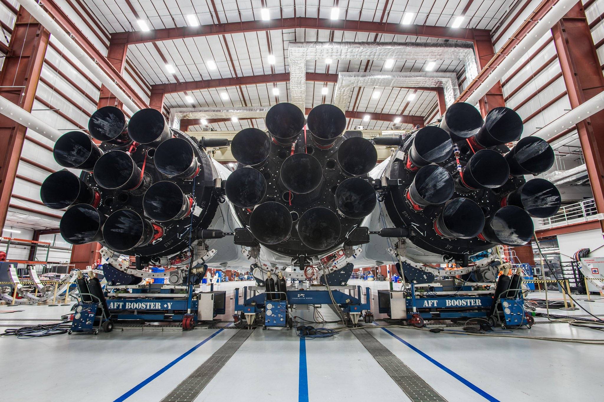
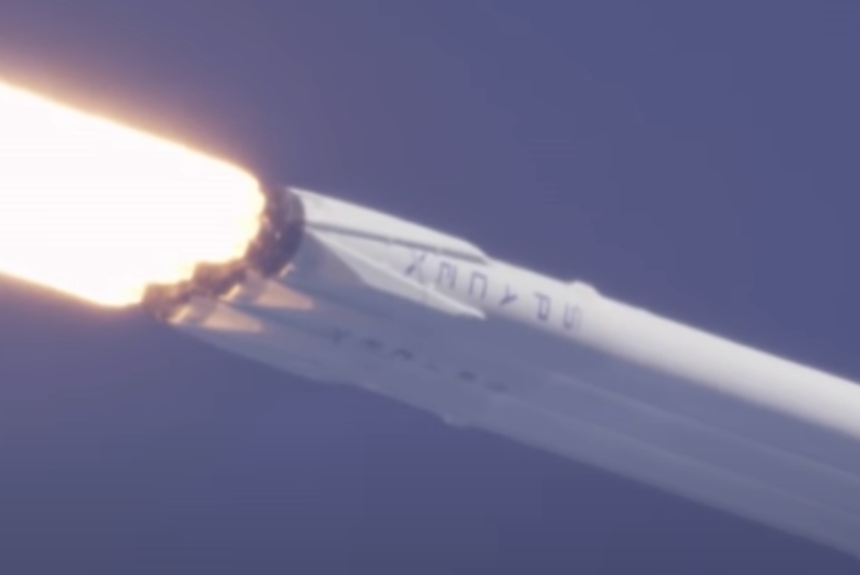
On Feb 6, 2018 SpaceX conducted their first Falcon Heavy test flight. They used Elan Musk’s red Tesla Roadster as the payload. You can view the actual launch here. And you can track the current location of the Roadster here.
Oy8O2rAK8MJCmRPRKWzwN32zOaYTMQC3UPeZDi8C-ThQ6uPnhEHPHjQiSJreZd5CkohPfoL4HWUWk5Vt4ED19K8MPUr5PobOp1upuEShX3Fwhfdv6_YXCdXOY8fgKPoSa2XaogNQ


Here, I present my latest build (3.0) of this rocket at 1:90 scale. This is a three cluster, 2 stage model with booster separation at Booster Engine Cut Off (BECO), second stage ignition at Main Engine Cut Off (MECO), and a Red Tesla Roadster as the payload. This scale allows the use of BT-60 tubes for the core rocket and booster bodies and a BT-70 tube for the payload fairing. The design uses Estes E12-0 or D12-0 motors for the core, and C-6-0 or B6-0 motors for the boosters, with an A8-3 motor in the second stage.

It measures 78 cm high and weighs ~460 grams (without motors)

In the most recent versions of my SpaceX Falcon models, the landing legs extend for an attempt at upright landing of the boosters and core rockets. You can see how the landing looks at the end of this launch of my 1:65 scale Falcon 9 Crew Dragon.

This is my 3rd build of this rocket at this scale. With each build I have added new features and fixed problems with previous builds. Here is the history of my progression of this model:

Build 1.0: used a model Falcon 9 kit from SpaceX for the core, BT-60 tubes and parts from Boyce Aerospace Hobbies for the boosters, and custom made booster mounts and motors. Features included:
  • 3 core, 2 stage rocket
  • Booster separation at booster engine cutoff (BECO)
  • Second stage ignition at main engine cutoff (MECO)
  • Recovery of boosters and core using rear ejection of the rocket motor tube
  • Magnetic shear pins for booster attachment/separation
  • Replaceable parts: minimal use of glue
  • Payload: Red Tesla Roadster

This model flew successfully on 11/27/2019. It also flew successfully as a Falcon 9 (without the boosters) on Feb 20, 2020 at a SARG club launch in Sacramento CA.

Build 2.0: In addition to the above, features include:

This model has yet to fly successfully due to repeated cluster ignition failures. It turns out that reliable cluster ignition is hard.

Build 3 (this build): In addition to the above, features include:
  • Use of self adhesive paper “skins”* adapted from AXM Paper Scale Models.
  • Use of snap-in parts**
  • No paint***. On Build 2, a significant amount of effort was spent on painting and wet sanding and I never figured out how to apply SpaceX graphics over the 3D printed parts.
  • Hybrid BT-50/BT-20 core motor tube. The BT-20 tube extends from directly above the part that houses the motor to the 2nd stage, which permits more room for the recovery chute. This also allows for more powerful (D and E) motors which Build 2.0 did not.
  • Magnetic booster attachment of the upper booster mount with magnetic-puenatic separation (basically I learned in the 2.0 build that puenatic separation alone does not work).
  • 3D printed parts using two colors (black and white) in the same part
  • Magnetic lower booster attachments.
  • Improved reverse recovery mechanisms
  • Improved techniques for using tape to secure motor parts.
In this version, I corrected a number of bugs in the 2.0 build.
  1. The addition of the lower booster mount arms improve booster stability.
  2. Refined reverse recovery parachute retention and release using an all new technique.
  3. Also note that the first three features above make for a significant reduction in the build time for this rocket.

*These were first developed on my Space X Falcon 9 Crew Dragon BT-60
**This was introduced on my Falcon 9 Crew Dragon Build 2.0
*** This build still has paint on the nose cones but everything else is White PET plastic or self adhesive paper printed on a color printer.

I plan to do the first flight of this model at that SARG club launch on April 23rd 2022.

Photo of (almost) all parts:
1673051552744.png

Finished build:
IMG_1577.JPG

IMG_1578.JPG

Close up of landing legs
IMG_1579.JPG

Retracting thrust struts


Flip-out-fins on second stage
IMG_1581.JPG

Booster attachment and separation work like my previous Falcon Heavy builds
1673051789589.png

Due to the character limit of this forum, I'll have to upload additional information about his build in a follow up post.

As mentioned above, I plan to do the first flight of this model at that SARG club launch on April 23rd 2022. I'll let you know how that goes.
 
Last edited:
Table of all parts

Part NamePart DescriptionQtyDimensions (mm)Unit Mass (g)Total Mass (g)
BT-20 Nozzle RTPBell Nozzles for 18mm motors160.386.00
Bell nozzle mount BT-20 RTPCore motor mount (bottom)23.957.90
BT-20 Upper Motor tube mount part 1 RPTThe upper motor mount is printed in two pieces that can be glued together to form the attachment/repulsion magnets needed for booster attachment/separation21.302.60
BT-20 Upper Motor tube mount part 2 RPTThe upper motor mount is printed in two pieces that can be glued together to form the attachment/repulsion magnets needed for booster attachment/separation22.004.00
booster top section with nose cone V 2 RTPNose cone with holes for booster attachment parts.211.8023.60
Landing leg magnet ring RTPHolds landing legs upright24.408.80
Booster lower section with strut mounts RTP28.5017.00
Landing leg V2 Landing leg RTPLanding legs84.8338.60
Booster BT-60 LOX Top Part RTP21.402.80
Booster BT-60 LH2 Top part RTP20.651.30
BT-60 Lower LOX section RTPLOX fuel line lower section32.306.90
BT-60 LOX 2nd section RTPLOX fuel line lower section 231.003.00
LH2 line RTP60.00
LOX fuel line section RTP60.00
Landing leg sheild v2.1 RTP120.00
BT-60 tube337820.9062.70
BT-20 tube34572.738.19
BT-50 tube1893.503.50
BT-20 tube motor stop20.501.00
19mm motor retainer cliptwo 19mm motors on boosters + one 199mm on second stage30.772.30
24mm motor retainer clip11.001.00
Grid fin mount RTP120.081.00
Grid fin RTP121.0012.00
Eyelets for landing legs120.00
Magnets for landing legs120.00
Magnets for landing leg magnet ring123x61.6019.20
magnets for lower booster center attachment23x61.603.20
magnets for lower booster strut attachment43x61.606.40
magnets for upper booster center attachment43x61.606.40
magnets for upper core booster center attachments23x61.603.20
magnets for core - booster Center attachment24x100.00
Aluminum tube for landing leg upper tube1260.120.00
Aluminum tube for landing leg lower tube1254.70.00
AXM Paper skin lower section20.00
AXM Paper skin upper section20.00
18" Recovery chuteCore and Booster parachute30.00
Falcon Heavy Bell nozzle mount BT-50 RTP13.903.90
BT-50 Nozzle RTPBell Nozzle for 24mm motors80.383.00
BT-20 Tube Upper Motor Mount RTP11.501.5
BT-50 to BT-20 coupler RTP11.701.7
Lower core landing leg section with improved booster mounts RTP110.0010
Interstage with Grid fin and exhaust holes v2.003 RTP17.407.4
Core BT-60 LOX Top Part RTP00211.701.70
Core BT-60 LH2 Top Part RTP10.800.80
Thrust Arm with Hinge for PLA arm 2mm RTP40.281.10
upper booster mount part RTP20.00
3/8" dental rubber bandsRubber bands for thrust strut retraction20.00
Thrust Arm eyeglass screws40.00
Landing leg V2 Landing leg w find slot RTPLanding legs44.8319.30
fins42.6010.40
AXM Paper skin lower section10.00
AXM Paper skin upper section10.00
2nd stage motor Lower section to print18.308.30
2nd stage motor Upper section ready to print15.205.20
2nd stage flip out fin41.686.70
3/8" dental rubber bandsRubber bands for flip out fins8
BT-60/70 coupler RTP18.808.80
Falcon Heavy Nose Cone RTP117.8017.80
BT-60 tube1955.005.00
BT-60 tube166.53.503.50
BT-70 tube1896.206.20
AXM Paper skin upper section10.00
12" Recovery chute10.00
Launch lugs2
Red Tesla Roadster1
Total249373.89
 
Last edited:
Here you can see the lower booster section printed with black and white PET in the same part. At the nose cone, you can see the holes for the snap-in grid fin mounts and other parts. The motor tube is also shown with the magnets for booster attachment and separation. You can also see the four magnetic sheer pins that hold the landing legs in place.
HC08apXnkfFawSnhjdd4G76z3AvVYVd8-teXQb1QIgmBfJEggyBBfwEI7iVCq75BLj2XgD4QNRIdkMhTpoQTgCIjMrTQdRz5xSGDtlQcFJEWAme9l4lJDpNqJXxiUrGw_vZ0Lkdh

IMG_1436.JPG

IMG_1437.JPG

Each landing leg has a small magnet in the end, which is how it is held upright until the motor ejects from the rocket during reverse recovery. Here I'm press fitting a magnet into the tip of landing leg.
IMG_1419.JPG

Test fit of lower booster mounts (no magnets on lower booster arms)
IMG_1427.JPG

Test fit before applying skins:
IMG_1443.JPG

Here this lowest section of the AXM paper skin has been applied:
IMG_1453.JPG

-n3YL_fzTwUnuKdaeVf0nd4iJ0qJR8BDQwOAlfS_0e3Jhfk6d4Wuytna-ktX6BN9h6Zo2Zlf8zIcU41UMASqikkN7XIWdlsvP83ZuA0ei5xPaE4OZ2PLvSL3ZtpsIE-hnejr6FXe


The paper skins are printed on self adhesive (sticky) paper
IMG_1441.JPG


The skins act as "the glue" to hold sections together:
BZU8_35SgQ4EPk6wiVauAPc-8CQ10Y0HMe6KuFzYMqfyAeiGCW2SsexFI2DxR6GieNKHHcQA8vPdEmYP1oV9oCbSVG_BOT9tMHpqGp4v4PmwTNkbNHbzdP0v0UU-LRNe-uelAVkl


Here is the interstage section of the core rocket with the booster mounts being test fitted. The grid fin mounts can also be seen in this photo -they snap-in to the square holes on the interstage section. The round hole on the interstage section is hidden behind the grid fin & allows cold air to escape from the motor tube when the ejection charge ignites, this prevents the 2nd stage from popping off like a Champaign core and facilitates ignition of the 2nd stage. It also cause the grid fins to flip outward for the landing.
IMG_1417.JPG

Close up of booster mounts with magnets
IMG_1426.JPG

Grid fins extended.
Grid fins.jpg

Landing legs extended:
close up of landing legs.jpg
I was using electrical tape to secure parts together but found that it does not perform well over time.

IMG_1438.JPG

Now I'm using gorilla tape that has been cut to size to get a much cleaner application.
IMG_1582.JPG

Here is the additional lower booster mount that I added for stability
IMG_1587.JPG

The metal parts are small magnets (2mm x 1mm x 8mm) to try to model the metal arms on the Falcon Heavy booster mounts.

O1LXE.jpg
 
Last edited:
Time to prepare the Falcon Heavy for transportation:

So I designed and printed these mounts.
1652935122980.png
1652935162262.png
1652935213556.png

The base of the mounts has holes for fasteners but can also be secured using 1" adhesive Velcro strips.

IMG_E2055.jpg
Hopefully you didn't notice the white 1/16th inch shock cord I'm using to attach the recovery parachute to the nose cone area. Not until I pointed it out anyway. There's a loop of shock cord running under the grid fins of the booster in the foreground. And you can see it running between the engine nozzles on the left. Hiding the shock cord is on my short list for my next version of this rocket. In the next version, I think I can use 1/16" and 1/18" shock cord in place of the liquid hydrogen LH2 and liquid oxygen LOX fuel lines and almost completely concealed.
 
Last edited:
Here's the Falcon Heavy at Artesia Dry Lake, NV on 05/21/22
IMG_2100.JPG

This is with two C6-0 (one in each booster), and E12-0 in the core, and an A8-3 in the 2nd stage.

Note that while the boosters can be fitted with D motors, I'm intentionally keeping the booster motors under powered so that I can observe the flight and minimize damage.

At first, things appeared to be going well. But the expected roll was followed by a pitch to horizontal and then things got worse.


Here is my breakdown of events:
Shortly after takeoff, the Falcon Heavy pitched to a horizontal flight path:
View attachment 519959


This was immediately followed by an unplanned right booster separation:
1653360410572.png

By this point, the right booster has flipped around with the motor still burning.
1653362621091.png

and then the motor is (finally) ejected from the booster (but not completely):
1653362776795.png

But now the core is also tumbling. Here you can see the core flying backwards and the motor ejection from the right booster never completes:
1653363015974.png

Now, after a complete flip, the left booster has separated and the core can be seen clearly with landing legs deployed but no revere ejection of the core motor:
1653363294967.png

A lot is happening in that cloud of exhaust:
1653363708647.png
2nd stage ignition occurs but the core motor is not ejected. Meanwhile the left booster has ejected its core and recovery has initiated.

Now all of the pieces fall (LOL) into place.
1653364023424.png

Lastly, we can see the 2nd booster recovery working pretty much as best that can be expected: landing legs down
1653364108235.png

I'm learning to treat recovery of parts after these flights like a crime scene:

Right booster:
IMG_2105.JPG
Core photo missing

I'm pretty sure the 2nd stage ejection occurred on the ground but nothing was damaged.
IMG_2103.JPG


So there it is.

FAIL or WIN (you get to decide):

Here's my scoring.

Fail
1: Horizontal pitch just before BECO
2: Unplanned right booster separation
3: Failure of reverse ejection of the motor tubes for the right booster and core
4: Hard landing of the right booster resulted in the loss of a bell nozzle
5: Hard landing of the core resulted in destruction of the lower 3D printed core body section and motor mount. One fin is missing and another needs to be replaced due to blackening from motor exhaust.

Win
1: Successful ignition of all three cores
2: Successful ignition of the second stage
3: Both boosters were recovered with no damage and can be flown again with no repairs.
4: Despite the missing and broken parts noted above, this rocket can be repaired and flown again because the rockets can be disassembled by removing the adhesive paper skins and gorilla tape that holds them together.

Root cause analysis. Items 4 and 5 on the FAIL list are a result of items 1 - 3:
1: I think the unexpected pitch was due to the Red Tesla Roadster payload. I did not take care to make sure that it was centered in the payload fairing. My solution (for now) is to add a 3D printed mount for the Roadster to secure it in the nose cone as far to the top of the rocket as possible.
2: I think the right booster separation was a result of the rotation of the rocket to a horizontal flight path during flight. The booster mounts are designed to secure the boosters to the core when held upright. The entire rocket can be lifted by one booster in the upright position (previous builds required that two hands be used at all times). The booster mounts are also secure if the rocket is handled from the core in a horizontal position. But I think that the rotation of the rocket to a horizontal position caused the booster separation. Hopefully (if problem 2 is related to problem 1) both will be solved by improving the axial center of gravity (COG) of the entire rocket. Obviously booster mounts could also be stronger but that will require a new design of the booster mounts. I should not forget to mention a small problem that I ignored prior to this flight. I had added small magnets to the lower booster mounts and noticed that one of them was siding in its mount and allowing the right booster to rotate a very small amount on the center line. This would have been fixed with a droplet of superglue but I forgot to correct that before the flight.
3: I still need to do a tear down of the core and right booster to get a better understanding of the problems that occurred here. In general, this has been an area of focus and concern. I need to develop a more reliable way to pack the parachute and prevent it from shifting both during the acceleration of lift off and reverse ejection. I was discussing the problem with Steve (who attended the launch with his family) and we struck on the idea of using a clear tube for the rocket body to actually see what is going on there.

That is what I have to report so far. I still need to tear down the rocket and make repairs. On a positive note: I got my Level 1 Certification with my Apogee Zephyr on this same weekend. And between the lessons learned on this 1:90 scale Falcon Heavy project and my 1:65 scale Falcon 9, I'm (slowly) making progress towards my goal of flying my 1:65 scale Falcon Heavy.

Special thanks to Wayne, Ron, and Jennifer from Rocketry Organization of Northern Nevada for making this launch possible.
 

Attachments

  • 1653360388318.png
    1653360388318.png
    126.3 KB · Views: 0
  • 1653362705305.png
    1653362705305.png
    51.1 KB · Views: 0
Last edited:
If that video is 'real time' as it looks to be, then I do not think you had enough velocity coming off the rod.
The arcing over is very typical of too low a velocity then things keep going bad.

What does the Sim give you for launch speed off the rod?
 
Back
Top