


Tonimus
Well-Known Member
- Joined
- Jul 8, 2014
- Messages
- 1,511
- Reaction score
- 11
I purchased a standard remote nixie tube clock board from https://www.open-rate.com/Store.html
It will drive standard sized tubes or smaller without issue. It has provisions for driving 6 tubes, 10 digits each, and running 4 ticking LEDs and 6 backlight RGB LEDs. The kit has an RTC module with battery backup that maintains the set time. It also comes with a photoresistor which automatically dims or brightens the tubes and LEDs to match the ambient light level.
This is my first attempt at a significant soldering project, and with it being all through-hole components, that made it a nice place to start.
I've been meaning to build one of these for a while. I ordered 18 tubes with sockets about a year ago and Christmas motivated me to build one for my best friend.
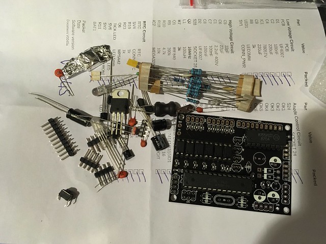
Contents of the bag of bits:
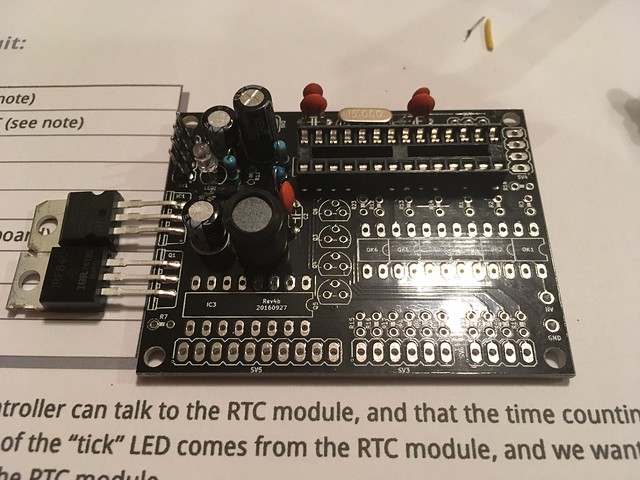
Low voltage (12v) circuit and soldered side:
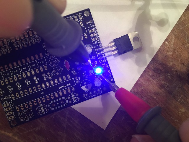
Testing the LED because I've never used the diode check on my meter:
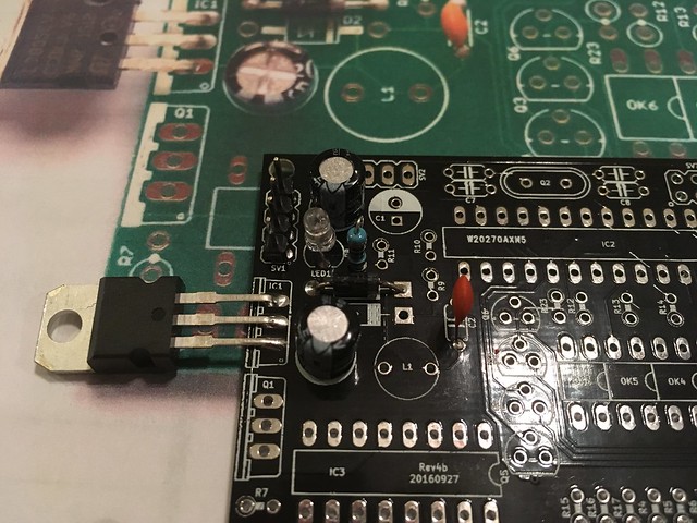
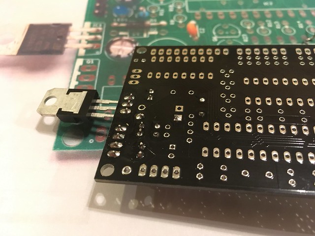
High voltage (150v-200v) circuit and soldered side:
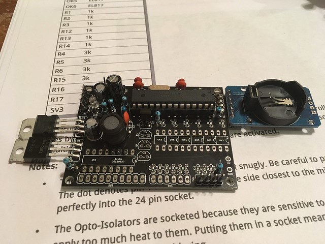
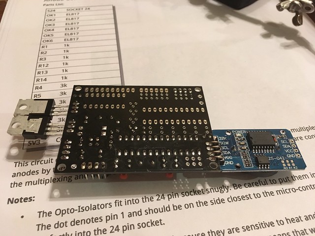
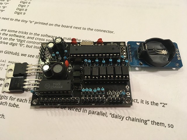
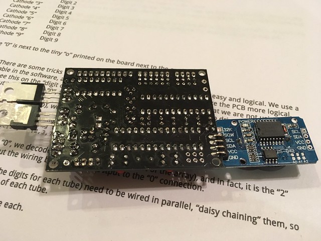
Pre-assembled clock board and main board crystal installed:
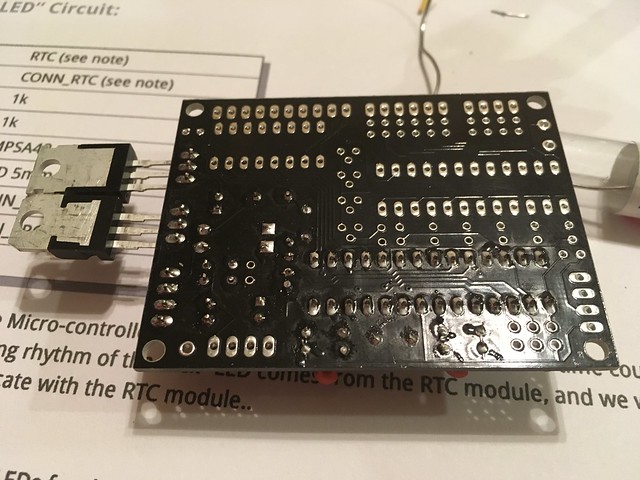
Last of the components on the board. Anode and cathode control circuits installed and header pins soldered on:
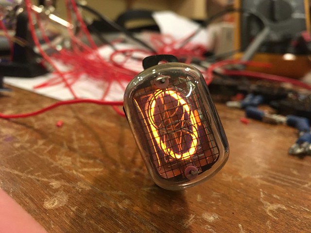
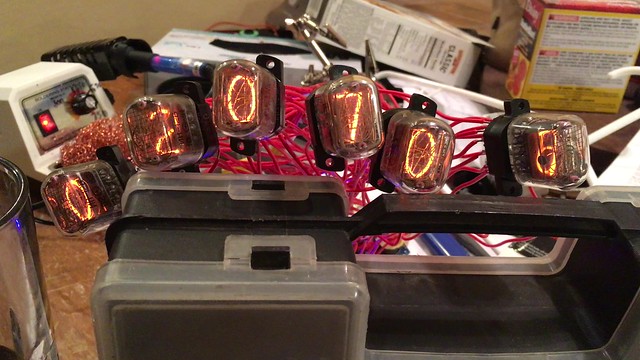
Test driving a single digit and confirming pinout of Soviet-era IN-12 nixie tubes.
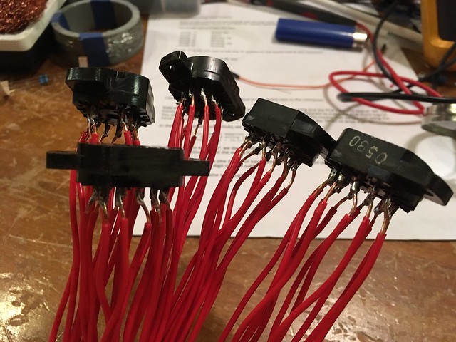
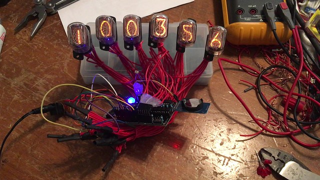
Soldered on the remaining five tube sockets:
Initial test run (click for video):
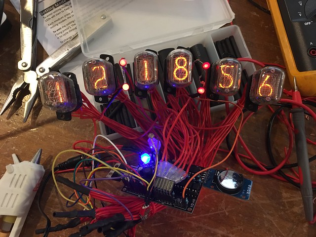
Bundles soldered, wires tied and running (click for video):
At that point, I thought I was done. I wasn't going to bother with the pulsing separator LEDs or backlighting. But after letting the clock run for a while, I decided it did need the tick LEDs...
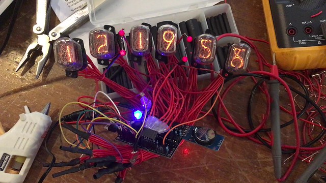
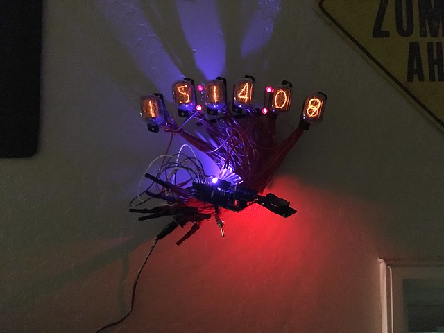
Running, with the tick LEDs (click for video):
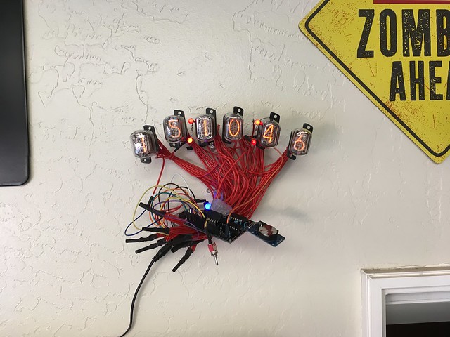
My buddy loved it. Here it is mounted on the wall of his shop:
It will drive standard sized tubes or smaller without issue. It has provisions for driving 6 tubes, 10 digits each, and running 4 ticking LEDs and 6 backlight RGB LEDs. The kit has an RTC module with battery backup that maintains the set time. It also comes with a photoresistor which automatically dims or brightens the tubes and LEDs to match the ambient light level.
This is my first attempt at a significant soldering project, and with it being all through-hole components, that made it a nice place to start.
I've been meaning to build one of these for a while. I ordered 18 tubes with sockets about a year ago and Christmas motivated me to build one for my best friend.
Contents of the bag of bits:
Low voltage (12v) circuit and soldered side:
Testing the LED because I've never used the diode check on my meter:
High voltage (150v-200v) circuit and soldered side:
Pre-assembled clock board and main board crystal installed:
Last of the components on the board. Anode and cathode control circuits installed and header pins soldered on:
Test driving a single digit and confirming pinout of Soviet-era IN-12 nixie tubes.
Soldered on the remaining five tube sockets:
Initial test run (click for video):
Bundles soldered, wires tied and running (click for video):
At that point, I thought I was done. I wasn't going to bother with the pulsing separator LEDs or backlighting. But after letting the clock run for a while, I decided it did need the tick LEDs...
Running, with the tick LEDs (click for video):
My buddy loved it. Here it is mounted on the wall of his shop:
Last edited:
")