


- Joined
- Feb 14, 2017
- Messages
- 210
- Reaction score
- 54
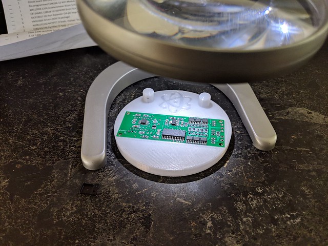
Here is my latest project, an Eggtimer Proton kit using a solder stencil and solder paste.
Chris was nice enough to release the Cream files for the Proton and hopefully this post will inspire him to release the files for all eggtimer products and to show people how its done.
Step One create the stencil.
There are many website that sell stainless steel stencils also guides on youtube on how to turn a popcan into one. For me I belong to a local maker space so I have access to a laser cutter so that is what I will explain.
A. Melt the soder. This is where it would be nice to have a reflow oven, although I did have access to one at maker space I choose to make my own using an old junk toaster oven I got from good will for $5 and a premade circuit board from rocketscream.com altogether I had about $50 in making it, you can either make your own or hopefully have access to one at local maker space. Some people will say that you can just throw it in a regular oven heat it up to X degrees and you will be fine, and maybe you will but to me I wanted to do it correctly with a reflow curve.
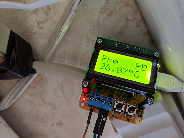
I told ya it was cheap")
B. After it goes the the reflow curve let it cool down to room temperature before handling it
Thats really all there is to it. I did not create a stencil for the top side since there was only a couple parts instead I just used the needle tip of the solder dispenser and placed a tiny dot on each pad. It did not look as good as the stencil but way better then I could hand solder.
Here is final product
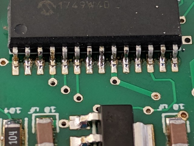
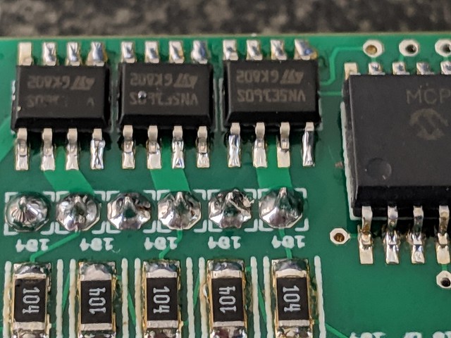
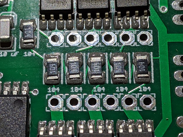
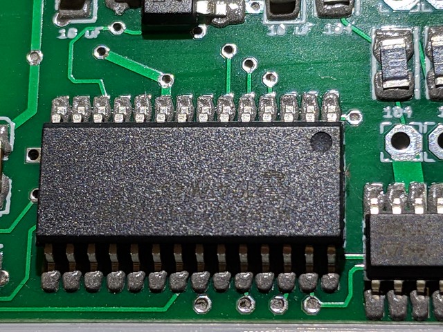
Its not perfect but its close enough for me. As you can see all the bridges are gone as the solder will suck into the nearest pad. I did have 2 solder bridges on the 24pin chip but they where very easy to remove.
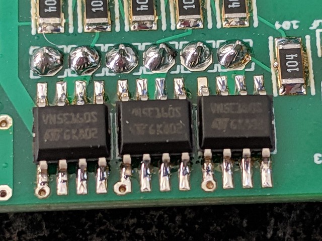
I have 100% confidence it will work even though its not perfect, coverage is not equal on all pads but I think a larger stencil would of been better option. I know the pictures dont always do it justice I assure you all the pads are soldered completely but some legs do have more solder then others.
Hopefully this will help anyone wanting to try this on your next assembly. From the time I started assembling including the 2 re flows top and bottom and all the hand soldering it was less then 1 1/2 hours I Im sure I could do a second in less then an hour but this was sort of a learning experience for me as well.
Any questions feel free to ask I will try my best to answer them.
Chris was nice enough to release the Cream files for the Proton and hopefully this post will inspire him to release the files for all eggtimer products and to show people how its done.
Step One create the stencil.
There are many website that sell stainless steel stencils also guides on youtube on how to turn a popcan into one. For me I belong to a local maker space so I have access to a laser cutter so that is what I will explain.
A. Open the Ger file in a Gerbal viewer program, I choose viewmate.
B. its best to shrink the pads since laser cutters tend to over burn the cut area, I shrunk all the pads by .001 and that seemed to work good.
C. Export the design to PDF, you can also print to PDF since some software does not allow you to export
D.This step is different depending on laser software, I then imported the pdf into inkscape and added 2 10mm holes to the top of them, unfortunately Chris did not include the drill holes with cream layer so lining them up was alot of trial and error I think it took me right around 20 cuts to get it lined up with the mount. I 3d printed a custom mount to keep the bottom side elevated and just make its generally easier to assemble being able to move it around in circles compared to being taped to the desk. Burn the image onto laser safe plastic like mylar or duralar I used .005 for this project but will try .01 for next.
Step Two Solder PasteB. its best to shrink the pads since laser cutters tend to over burn the cut area, I shrunk all the pads by .001 and that seemed to work good.
C. Export the design to PDF, you can also print to PDF since some software does not allow you to export
D.This step is different depending on laser software, I then imported the pdf into inkscape and added 2 10mm holes to the top of them, unfortunately Chris did not include the drill holes with cream layer so lining them up was alot of trial and error I think it took me right around 20 cuts to get it lined up with the mount. I 3d printed a custom mount to keep the bottom side elevated and just make its generally easier to assemble being able to move it around in circles compared to being taped to the desk. Burn the image onto laser safe plastic like mylar or duralar I used .005 for this project but will try .01 for next.
A. Apply a thin layer of solder paste across the top of the stencil. About 1mm thick
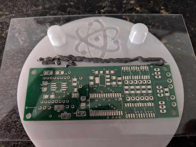
B. Use old credit card or similar to make ONE pass down, if you mess up and not get all the pads covered you must clean it all off and start again never do multiple passes because the stencil will move slightly and it gets ugly very quick.
After Spread
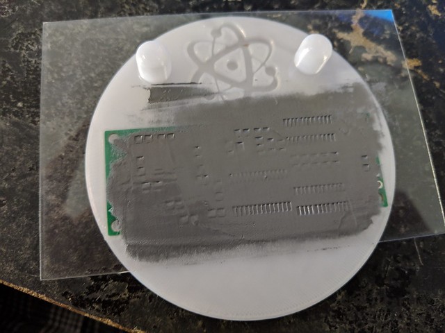
As you can see there is ALOT of bridging which I can assure you is completely fine at this stage as long as you made only 1 pass there will only be approx .005 thick solder on top.
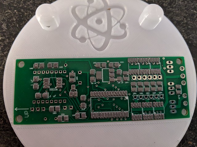
C. Place the SMD parts in any order you want but I did use the same order that is in the instructions so I wouldn't lose track.
As you can see there is still some bridging but as long as its not excessive it will be fine for the next step.
Step 3 Cooking the solder
B. Use old credit card or similar to make ONE pass down, if you mess up and not get all the pads covered you must clean it all off and start again never do multiple passes because the stencil will move slightly and it gets ugly very quick.
After Spread
As you can see there is ALOT of bridging which I can assure you is completely fine at this stage as long as you made only 1 pass there will only be approx .005 thick solder on top.
C. Place the SMD parts in any order you want but I did use the same order that is in the instructions so I wouldn't lose track.
As you can see there is still some bridging but as long as its not excessive it will be fine for the next step.
A. Melt the soder. This is where it would be nice to have a reflow oven, although I did have access to one at maker space I choose to make my own using an old junk toaster oven I got from good will for $5 and a premade circuit board from rocketscream.com altogether I had about $50 in making it, you can either make your own or hopefully have access to one at local maker space. Some people will say that you can just throw it in a regular oven heat it up to X degrees and you will be fine, and maybe you will but to me I wanted to do it correctly with a reflow curve.
I told ya it was cheap
B. After it goes the the reflow curve let it cool down to room temperature before handling it
Here is final product
Its not perfect but its close enough for me. As you can see all the bridges are gone as the solder will suck into the nearest pad. I did have 2 solder bridges on the 24pin chip but they where very easy to remove.
I have 100% confidence it will work even though its not perfect, coverage is not equal on all pads but I think a larger stencil would of been better option. I know the pictures dont always do it justice I assure you all the pads are soldered completely but some legs do have more solder then others.
Hopefully this will help anyone wanting to try this on your next assembly. From the time I started assembling including the 2 re flows top and bottom and all the hand soldering it was less then 1 1/2 hours I Im sure I could do a second in less then an hour but this was sort of a learning experience for me as well.
Any questions feel free to ask I will try my best to answer them.