PML Patriot 7.5 inch 98mm build

The Rocketry Forum

Help Support The Rocketry Forum:

This site may earn a commission from merchant affiliate links, including eBay, Amazon, and others.
Neils

You really don't need carbon fiber for this rocket, and it will present problems for transmitters as carbon is a conductor.

A potential problem with PML kits is fin flutter. Did your kit come with stock thickness fins, or are they the optional thicker ones. The stock thickness is definitely subject to fin flutter at or near transonic velocities. See https://www.publicmissiles.com/images/PMLG10FinsFAQ.pdf for details.

Also https://www.publicmissiles.com/images/PMLAirframesFAQ.pdf states that the PML factory glassed airframes use 2 wraps of 16 oz fiberglass cloth however this IMO is in error. The unglassed 7.5 inch airframe weighs 1 oz. per inch length and the factory glassed 7.5 inch airframe weighs 1.57 oz per inch length. 2 wraps of 16 oz cloth without resin weights 0.59 oz. per inch length so it's probably 2 wraps of 6 to 8 oz fiberglass cloth with resin.

Bob
 
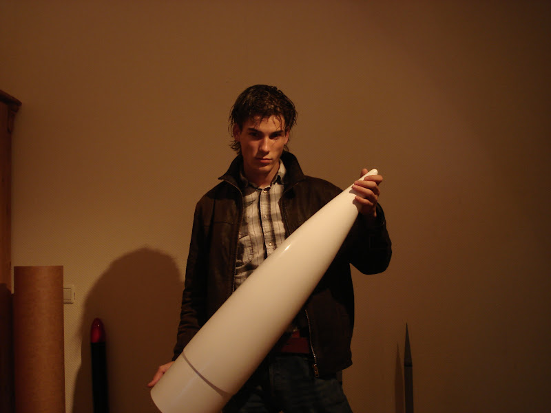
DSC02518.JPG

I love this shot. It makes me think "Twilight Builds Rockets". LOL
 
I love this shot. It makes me think "Twilight Builds Rockets". LOL

It makes me wonder if this is his James Dean imitation.

Hey, Neils,

I'm sure you have already considered this, but are you really going to be able to use those heaters without damaging the fiberglass covering or the bond to the airframe? If you turn the heaters "up" to a high setting, I would be concerned with thermal damage to the structure and contents of the rocket.

Just thinking out loud here (I don't know how much heat you need), but it might have been more simple to use an electric hair dryer/blow dryer plugged into the rocket. You would have to run out and remove it just before launch, but then again, you would not have to carry the extra heater weight during the flight.
 
I would be wondering if you would have trouble with the electronics with the temp changing so rapidly after removing the hair dryer. I have seen and experienced such failure from taking a rocket out of a warm car and going straight to the pad in cold weather. I believe the correct procedure is to let the rocket and electronics including the power source to acclimate to the temp it will be launched at. I do wonder about the temps aloft and if there is some degradation on performance. Maybe negligible for the temps we fly at in the winter and durations of the flights. Coldest I have launched at was 17deg. and a main chute charge did not fire. I thought it may have been the Batteries, that same day 3 other fliers had similar problems it was not until later we all made the same mistakes launching warm rockets. One reason I am interested in those heaters niels is going to use.
 
The heating system will heat up to 40 degrees Celsius,

the aluminum tube where the heating system is mounted on,
5 inches, and the airframe 7.5 inches

only the airframe gets a fiberglass layer.

the space between the aluminum tube and the airframe will be filled up with cameras watching outside the rocket.

A hairdryer is not useful for this experiment, cause it has a biological experiment on-board, and the gases inside the biological experiment has to be at a stable and control temperature.


I will show more pictures of that, when the work is done.


I'm thinking of place two or three backup altimeters in top of the nose cone.
small pipes connected to the pressure sensor of the altimeter.
will be connected to a condenser, where other pipes lead it to the outside air of the rocket.

why like this ?

cause I read something that turbulence can make failure to your altimeter.

also I'm placing a free fall sensor between the drag-connection and the main-connection from the altimeter,

to be sure that there will be not a to early apogee.

a free-fall sensor work verry simply and is easy to make by your self.
I will show tomorrow some pictures of how it works.


And thankz for advicing not to use carbon fiber.
I think I'll only make the fin-set in a layer of carbon fiber.


now with the upper section with a heavy weight, another problem has come up.
it is impossible to use a black powder ejection charge to eject the recovery.

Lucky I didn't glue to upper center ring yet,
the plan is now, to mount a pneumatic cylinder in the center ring.
that pushes the piston upwards

that way the weight of the upper section doesn't that matters
and I can use the pneumatic control I also used for the biological experiment


and now you maybe thinking how do you gonna do that with all that weight,
well every part I using in this rocket , I check there weight and the size, shape, location in the rocket, so I can calculate the CG,
to be sure it will be stable.

I also gonna ad a gyroscope to make it a little bit stable,


and why all that stuf,

well that the thing I love about rocketry
to make it advanced


edit English,

I'm just a guy from the Netherlands
 
well that the thing I love about rocketry
to make it advanced

Me too! I like it so far, I don't understand some of it yet as it looks like it is getting very heavy but this is a good place to work things out. With other people looking it helps some times :)
 
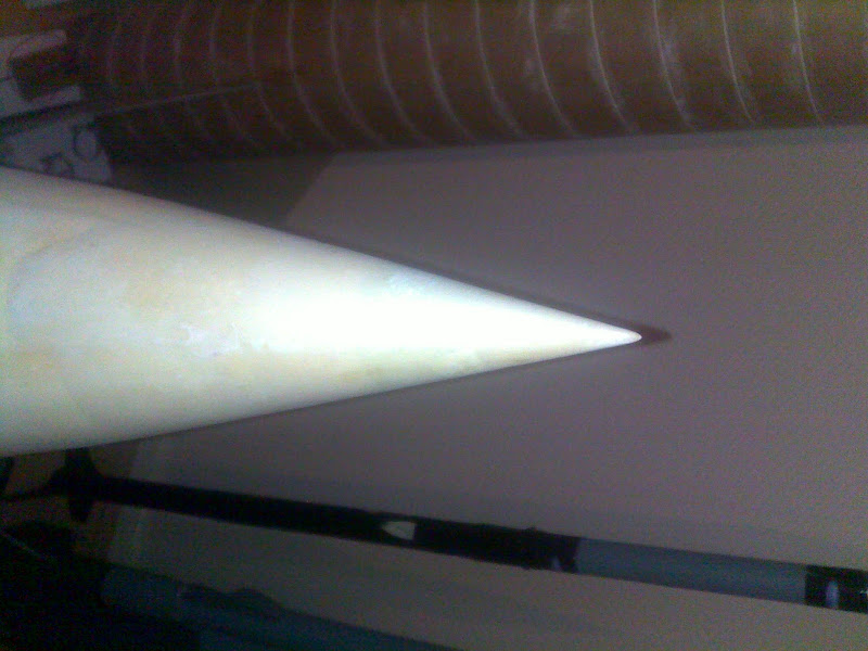
making a sharper nose tip, I've used Epoxy and some layers of paper together with some fiberglass to make these tip.
01112010827.jpg
 
Last edited:
edit English,

I'm just a guy from the Netherlands

You are using better English than half of this country is capable of. We are just happy to have you show your project (it looks like a lot of work!) here on TRF.

If we tried to talk in ...Netherlandese...(what language do you guys use? Dutch?) there are not very many of us that would do any better.

Placement of the pressure ports for your altimeters will indeed be influenced by turbulence. You will also get distorted pressure readings from the airflow changes around the nose cone. Pressure changes can cause the altimeters to think the rocket is going faster/slower/higher/lower than it really is, and mess up recovery deployment. The best place for pressure ports (and altimeters) is in a region of steady, smooth airflow like the side of the body.

But if you are locating the altimeters in the nose, you could also simply use an air data probe sticking out the front of the nose cone--where your altimeters already are. Make the probe long enough to reach out to "clean" air in front of the nose cone (20 cm? I'm guessing), and make a hole in the side of the probe just like you would make in the side of the body. Keep the air pressure source isolated in a sealed tube that runs straight back to the altimeter bay. In theory, this should accomplish the same thing.

Before using this approach you should check the surrounding airflow with a CFD model, to make sure your pressure port is out in clean air.
 
Better yet, if you're not doing Dual Deployment, and just popping a main chute at apogee, simply use accelerometers. No venting needed. It'll simplify an already very complex build.

R
 
30102010812.jpg


And thank you for the compliment of my English, I just love to improve it every single day.
 
Last edited:
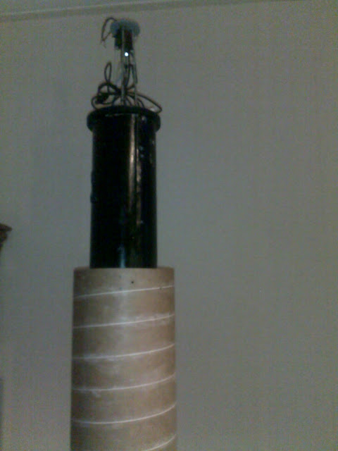
this pictures you above,
is the frame for the board computer, its build in the upper section and the nose cone.
it fits perfectly into the nose, I used bulkplates to make a transition first 7.5 inch than a 6 inch to a 2.5 inch bulplate,
under the 2.5 inch bulkplate I mounted a rs232 GPS system,
the messing color grid you see on the 6 inch bulkplate is to protect the GPS from the radiation of the experiment, more grid will be mounted soon. like a faraday cage

and where is the radiation from?

the 120KV lightning that will be used in the experiment gives some bad radiations for electronic and stuff
 
now its just waiting until the summer starts again,
its to cold to fiberglass


I will show you more when its done.

now starting new building project beside this one.
like the upscale XP raptor ( Qmodelling orginal)

Edit: I mean break,
 
Instead of using fiberglass, I applying a aluminum plate (0,8mm)
on the booster and second section of the body tube,

three reasons,

one: It protects the rocket better for ejection, impact and zippers
two: Its lighter than the layer fiberglass and parts of carbon fiber I planned.
three: Its cheaper than fiberglass


I'll show in a new topic how I place the aluminum layer around the body,
 
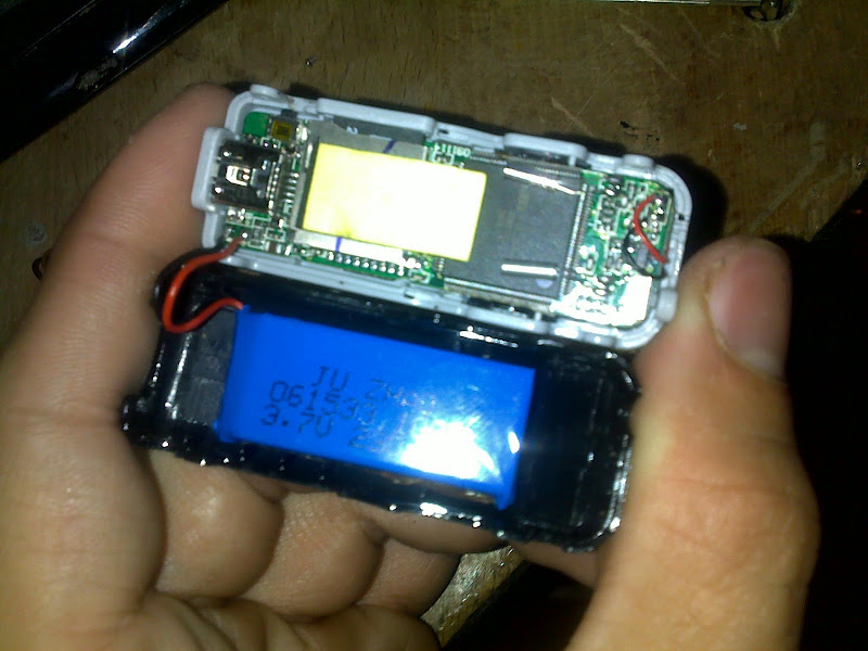
A camera, for inside the rocket experiment

08102010719.jpg
08102010720.jpg
08102010723.jpg


And the module fits now perfectly in the rocket.
09102010725.jpg
 
I would like to see more on your camera. Like where you got it and how you hook it up. It looks nice and small.
 
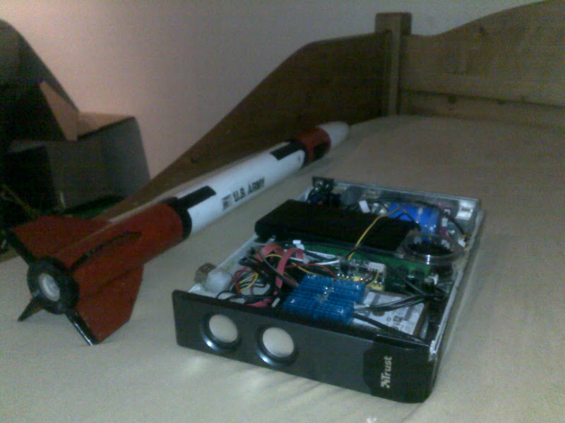
I just love this picture I made today,
a 1/10 scale patriot with a D12-7 engine, with a little damage of the previous flights
next to a mini-itx Intel Atom computer, I case-mod into a old speaker-box.

09102010734.jpg


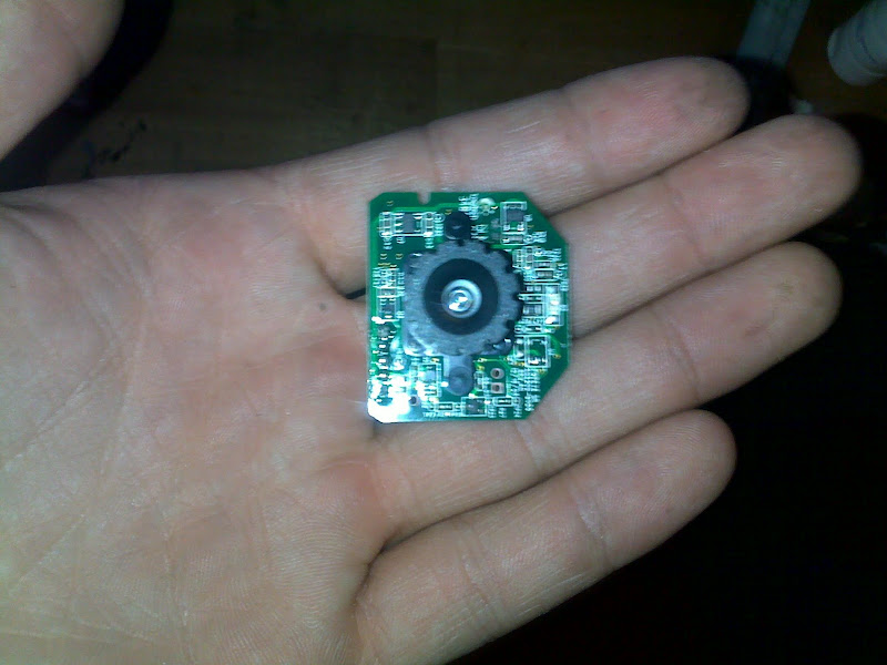
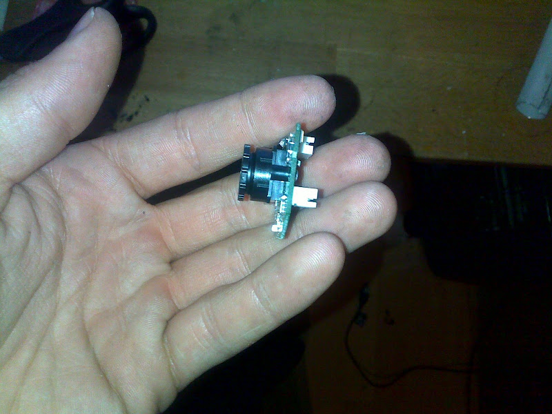
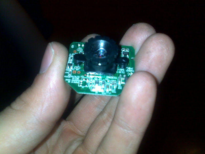
This camera is from a logitech web-cam
1024*768

I connect it with USB to the onboard computer inside the rocket,
this way i can connect more camera's and use the audio input for some sensors,

08102010719.jpg


I've seen more rockets with this board inside
This is a VIA Pico-ITX mainboard, it has a 1ghz c7 cpu onboard,
with 1gb ddr2 sodimm,
I want to use this with a SSD so it can survive to 30G,
it can run windows XP, the size is just 150mm * 100mm.
this board is not yet mine, I'll order it in a view months

027.jpg

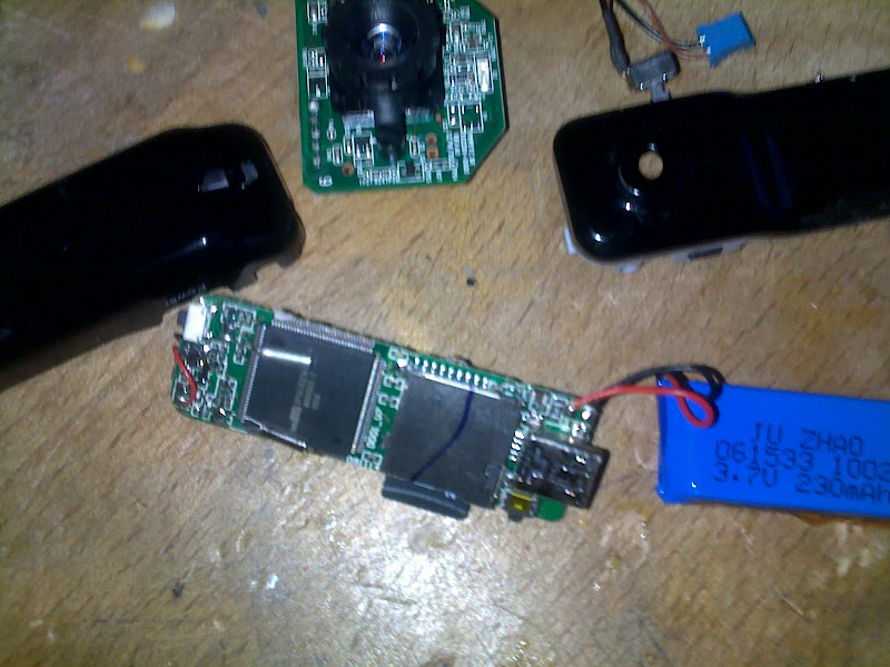
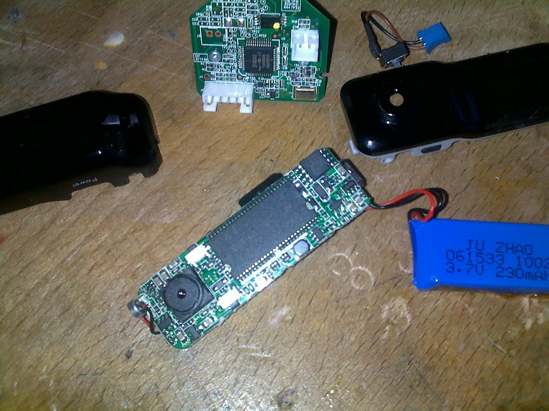
here another camera

its really small, and weight less than 20 gram,
I used it by more launches
it survived a free fall of 300 meters on a dirt ground.


https://www.amazon.co.uk/dp/B0034D3MDW/?tag=skimlinks_replacement-20

10102010736.jpg
10102010737.jpg
10102010738.jpg


I found my astronaut
09102010730.jpg
 
Last edited by a moderator:
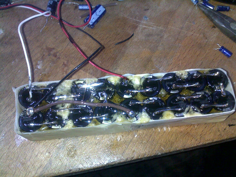
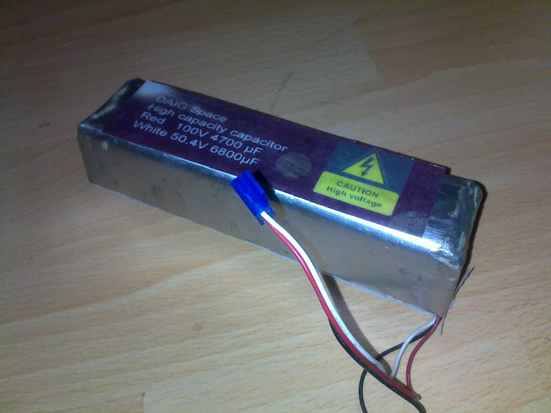
most rockets run on 9V, this one has a standard of 50.4V and 100V for the electronic equipment.

I use some capacitor for supplying the peaks of all the electronic equipments,
I use two capacitor banks in a single case made of aluminum and some glue,
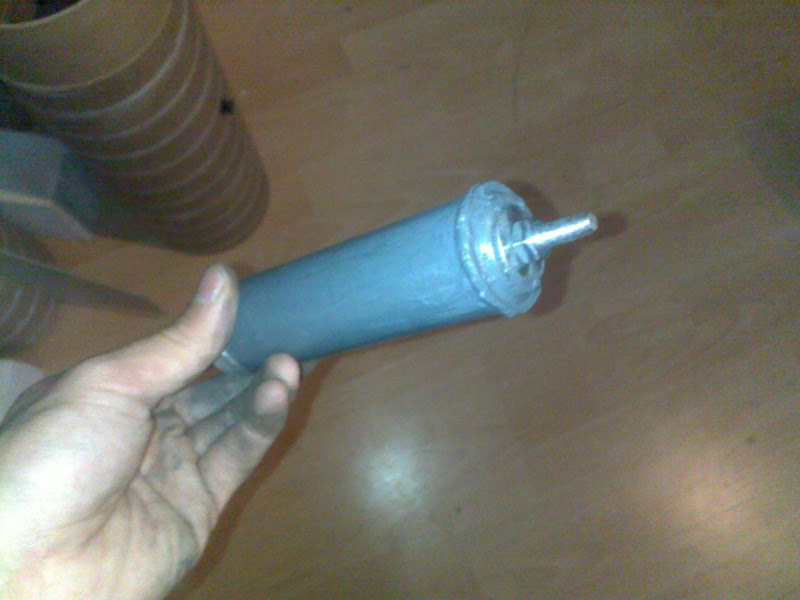
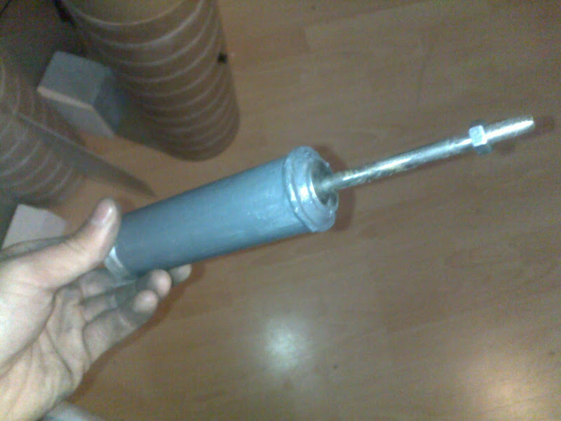
8 6.3V 6800µF and 10 10V 4700µF, here some pictures.

15102010744.jpg
16102010749.jpg


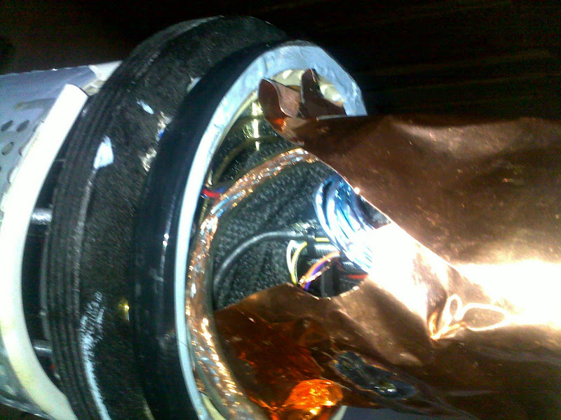
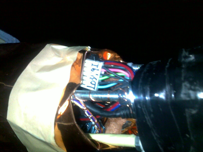
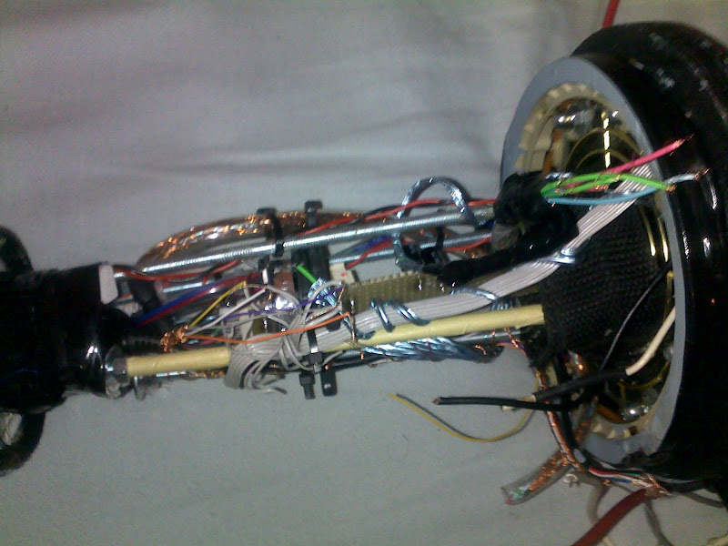
also the upper section of the payload has some upgrade in it.
placing the wires, adding some tape to keep things in place when the glue is drying.
as you can see are those wires protected with an layer of aluminum,
and the coper foil around it, make it a perfect Faraday cage.
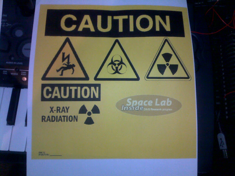
this will help to protect the electronics for X-ray thats produced by the experiment.
16102010762.jpg
16102010763.jpg
 
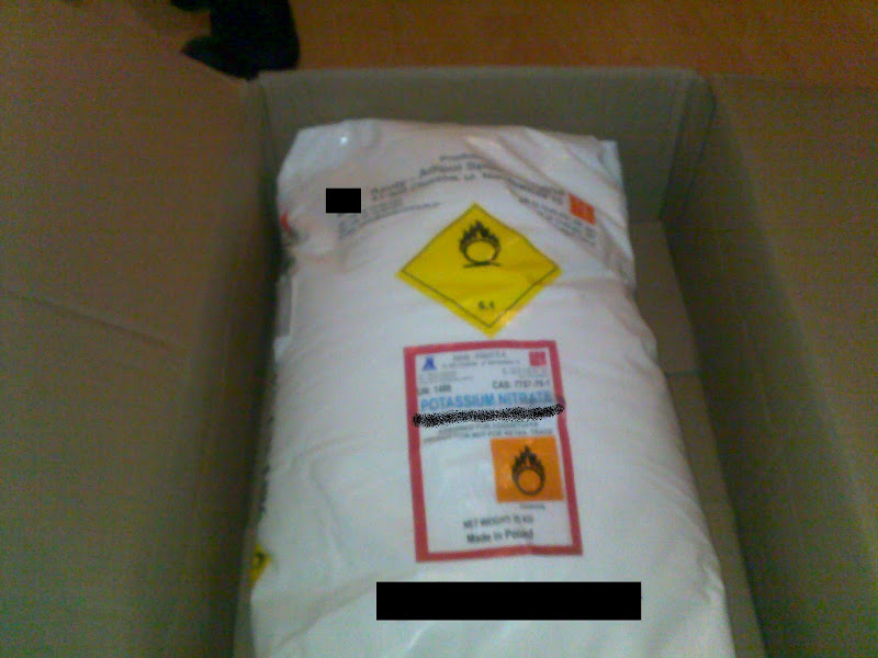
Why the black bars on the bag of potassium nitrate?
 
This is starting to look less like a rocket, and more like a bomb :>


Seriously, I've been playing with some high voltage capacitors on a few new builds for electromagnetic nosecone ejection. with all of that exposed metal, one wrong finger placement, and ZAP.....

I lost the nosecone plate of an experimental rocket at MWP8 last weekend, and had to warn the RSO that nobody should pick it up, as the capacitor was probably charged and it puts out 300 volts. not a lot of amps (run by a AA), but enough really wake you up.
 
Why the black bars on the bag of potassium nitrate?

well we don't like if wrong persons get this stuff in their hands.:y:
so I've painting the manufacture name away:D
 
Last edited by a moderator:
This is starting to look less like a rocket, and more like a bomb :>


Seriously, I've been playing with some high voltage capacitors on a few new builds for electromagnetic nosecone ejection. with all of that exposed metal, one wrong finger placement, and ZAP.....

I lost the nosecone plate of an experimental rocket at MWP8 last weekend, and had to warn the RSO that nobody should pick it up, as the capacitor was probably charged and it puts out 300 volts. not a lot of amps (run by a AA), but enough really wake you up.

well this capacitors ar not to eject,
its for the experiment, they are charged between 50KV and 165KV
when the rocket hits the ground, a sensor will detect the impact, and make the capacitors inactive, so it will be save to pick up at that moment.

and no its not gonna be a bomb, just some experiment to understand more about lightning, the potassium nitrate is only for the engine grains,
 
damn I did today some sample test for fuel:)

I will show pictures and video's soon,

I'm shocked, this way it can fly on a powerful engine, looking like a CTI N4800
 
06112010832.jpg
06112010833.jpg


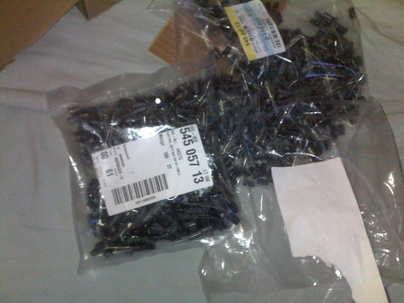
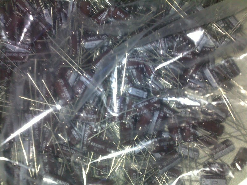
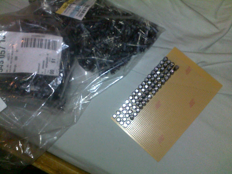
now the hard work getting thousands of capacitors together
06112010834.jpg


this will take a view months putting all together.
than i will test it on 165.000 Volt
 
well we don't like if wrong persons get this stuff in their hands.:y:
so I've painting the manufacture name away:D

Actually, here in the US. You can buy potassium nitrate easily from the internet, no permits needed at all.

I do admire your necessitation for safety though.
 
Back
Top