Optimizing an Inefficient Nozzle

The Rocketry Forum

Help Support The Rocketry Forum:

This site may earn a commission from merchant affiliate links, including eBay, Amazon, and others.

ClayD

Well-Known Member
Joined
Dec 10, 2010
Messages
2,440
Reaction score
8
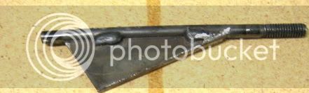
Okay, so today, I am going to fix this nozzle on my desk (dont have a camera so right now.... maybe some pics tonight on the lathe....)

I will post a drawing of specifications, but the L to the D ratio is "P00". and i want to make it better...

Plus if you have seen Charles Rogers info on nozzle efficiency, you can make a long L/D ratio strait cut nozzle better, by having less than a .303 ratio. and rounded entrance.

This means, that my nozzle, is too long... for the current expantion ratio. (dont know the half angle yet.)


here goes the first question...

Liner shoulder, is it required.. if so, why, if not why?

Second:

half angle, if it is at 15Deg, can it be reduced to 10deg, to allow a shorter throat.(i cannot make exit dameter any wider due to the trust ring, and flame plume being allowed to hit the exit of the case wall.)
i can notch the nozzle to get the same exit diameter further back .. and may do this to fit in a tad more propellant.
 
Liner shoulder allows you to have a reasonable tolerance on liner length and not have any case exposed to the fire. In other words with the shoulder on both ends the liner can slip back and forth and the case is always covered.

Since the graphite is soft a form tool can be made from mild steel to cut the radius. Just use a piece of steel about 1/8" thick and use an endmill to cut the radius then sharpen and cut back relief with a grinder or file.

Mark
 
Here's what I use to cut some basic entrance and exit angles.

tool2.jpg


Sanding also worksd fo rounding edges.

Tony
 
Liner shoulder allows you to have a reasonable tolerance on liner length and not have any case exposed to the fire. In other words with the shoulder on both ends the liner can slip back and forth and the case is always covered.

Since the graphite is soft a form tool can be made from mild steel to cut the radius. Just use a piece of steel about 1/8" thick and use an endmill to cut the radius then sharpen and cut back relief with a grinder or file.

Mark

Thanks, I had not consdired the idea of slack on the liner, I know my loki commercial always allows the closures to move back and forth a bit.
I though one of the manufacturers didnt make a shoulder. I cant realy remember, and is why I was curous about it.
I will not have slack in this liner, since i measure them to fit snug, so making the shoulder smaller will not hurt.


That will be a great way to cut the radius, and not expensive. I can throw away this sheet of .01 xy manual turns...
the mill idea, and the mill will prove usefull in generating future profiles..

i played with changing to 120degree cone, and using a radii at the throat, but i think i will leave as shown on this detail... it looks cooler, i wonder if the radius at the top end of the nozzle will be too steep and the cone would work more efficiently?


off to work,, the fun kind
 
Here's what I use to cut some basic entrance and exit angles.

tool2.jpg


Sanding also worksd fo rounding edges.

Tony

sanding scares me, escpecialy so close to the chuck. maybe a file.. or now that my brain is thinking, paper on a stick..
(before the mill idea, i had contemplated freeforming the radius, to "good enough with a file..."

i have plenty of 1/8" mild steel, so making some tools will do me good, time in the shop with friends does wonders.

(i was thinking about how hard it is going to be to do all this to an already short nozzle...) (getting the nozzle centered will be very difficult...

Thanks Tony and Mark.
 
Graphiite is easy to machine on a lathe, but use a shop vac to draw the dust away from the tool as you machine it.

Graphite is a bit abrasive, electricaly conducting, and very slippery. If you don't suck it away as you machine it, you can shorten the life of the machine, damage electric motors, and slip on the floor around the machine, not to mention that you get really dirty.

The area ratio of the nozzle looks low: I guess about 2.25:1 from your drawing. For the throat dimensions you show, a 1" exit diameter would give a 4:1 area ratio, and should give give better performance.

You are better off using a parabolic or elliptical upstream convergent profile instead of a round one. It is shorter and has less surface area for drag losses.

Bob
 
I put a generous radius on the entrance and exit. If they are 29mm and 38mm you can use step less drill bits from Harbor Freight to do nice exit cones.

image_1812.jpg


Here is what my nozzles look like:

58mm.jpg


Edward
 
i used sand paper and rounded things off... wanted to see how fast it was..

DSCN2232.JPG

DSCN2243.JPG
 
Bob, i cant do a wider exit diameter. The .78 or whatever, is pretty near the thrust ring, i would hate to fail a snap ring case by flame front weakening the case...
i will see about maybe changing this on a future nozzle.

I went with the round, just so i could learn here, the mill will allow me to get better curves later. still a day above what it was.

Ed, i ended up milling a beveled strap, those would work great, only i would have a hard time going the proper depth to get the right depth.. (i am pretty sloppy on the lathe... still fine tuning..)

the final shap, isnt optimum, and i cut more at 10degrees than 12, soooo... theres not much throat, i am sure it will erode... may be better than the .5 inch in the long run, on this long motor.

this nozzle should be much more efficient than what i had.... the onces i make from what i learned... will be even better.

DSCN2245.JPG

DSCN2249.JPG

DSCN2251.JPG

DSCN2252.JPG

DSCN2255.JPG
 
When I polish the inner surfaces I use #00000 Fine steel wool, really puts a shine to them. It also depends on your graphite grade.

Edward
 
When I polish the inner surfaces I use #00000 Fine steel wool, really puts a shine to them. It also depends on your graphite grade.

Edward

this stuff really shinned up durring cutting, i ran some really fine grit over it to smooth it out.. 2000... didnt work real well, gummed it up..
 
Nice Nozzle work Clay, I'm making some for a friend.
I hope to find time to make some for me!

Eric Foster
 
Thanks Eric, hopefully it works.

deffintatly a learning curve, i have found i should make the divergant cone, First, so that i can control the throat from the front, I/E, i couldnt really se what was happening on the up the nozzle as i was cutting. but i could on the throat...

the throat is a little thin, so i suspect it should erode, and be a 1 time use nozzle in this configuration. i can make the troat wider to make it regular shape if it does, and use it again.

the thrust ring, now sits flush with the end of the nozzle exit. gives me another .105" of propellant.
(all in all, i extended the propellant lenght 1/2" with my nozzle.)

DSCN2261.JPG
 
my unsuported hunch is about 5% increase.

My unsuported opinion of the previous nozzle was that it was sub 90% efficient. around 85.

so if it operates with 90 to 92 percent efficiency i will be a happy camper.

i havent done the math.
I chose the entrance radius by the standard 1.5Rt. wich as Bob Krech points out the radius will give some extra drag over an eliptical entrance. i could just use some sandpaper an knock down radius a bit.

The exit cone, is under optimal. it really lacks in the expansion ratio. Granted it is .53" longer than it started as.

i hope its aroun 92%

Ground test equipment, werent in this years budget. I spend most of my money on chemicals.

My plan, is to take my arts 2's. get accurate flight weights, and use the motor characterization to get a round about number, and compare to burnsim with nozzle efficiency variations.
(good enough for garage science i think.)

Probably fly at LDRS i think. my wife suggested i scrub this weekend, and save the propellant for ldrs... (who can argue that sound advice...)


may not fly the K motor configuration, I need the case for a certified J1000 i have.(wish i had a little skinny rocket for it at ldrs... such is life...)
 
"the exit cone, is under optimal"

so are you saying it's underexpanded?

is this a function of design, or is it a result of not enough area on your nozzle (graphite slug i presume?).

since it is not optimal by your own admission, how would you arrive at a more optimal design, and would it fit within the parameters of your rocket motor as currently designed. (ie, having the same dimensions).

i anticipate your answers.

yes, and no. optimal, as it the loose deffinition, of "preffered" was my intent there.
if you look at the nozzle before and after, there is an obvious "optimizaiton" and one is absolutely prefferable over the other.

Just not 4:1 like i would like, 2.25:1 is okay....

well, as you can see in my last photo, there is a stainless still ring that goes around the nozzle exit. this is my number 1 constraint in this specific instance. This graphite nozzle is slid into a "snap ring" style case. so the exit diameter is limited to keeping it from messing with the elements of the snap ring motor.

first, is its usualy inside the end of the case, so if its too wide, the hot exaust could cause the aluminum case to weaken, and fragment under pressure.

you could make this better, by using a nozzle carrier, and my opinion of going to a bell nozzle shape. I am not going to do either of these, since i am using a snapring motor, and the math for a bell shaped nozzle isnt somehting i have enough information to generate at this time. I simply dont know enough about the exaust at this point to "optimize" to that level.

this for me was a test run in machining graphite, and making something work, with existing hardware without modifying it. if i can net 10lbs more thrust .. cool...
the bell and carrier, are a lot of work for another 10lbs....

this nozzle was optimized more from removing the LONG throat lenght to diameter ratio more than anything.

DSC05494[1].jpg

DSC05497[1].jpg
 
Back
Top