ECayemberg
Well-Known Member
- Joined
- Jan 21, 2009
- Messages
- 2,874
- Reaction score
- 839
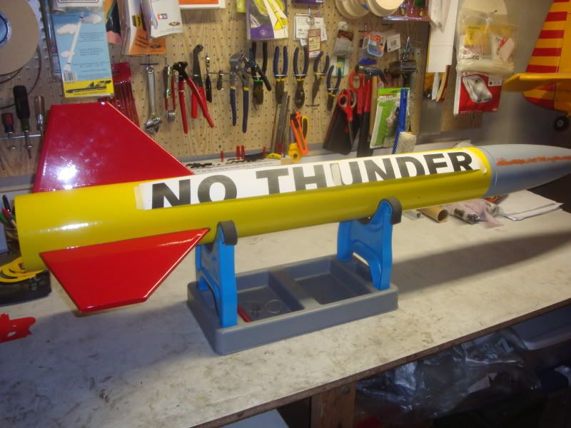
This build thread will be a little bit different than normal. Instead of detailing a “standard” build, I’ll detail only those items that are a little different than the norm.
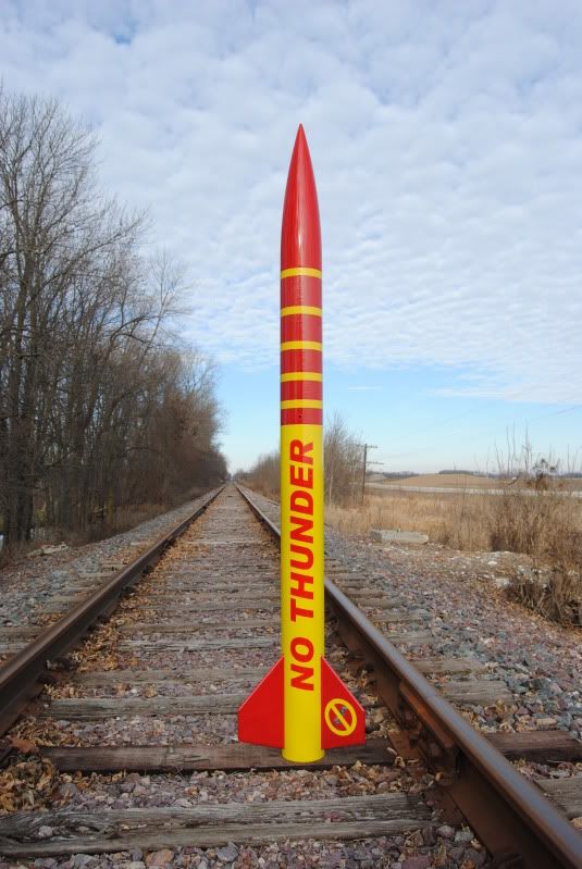
No Thunder: what’s in a name?
The name has a two-fold meaning:
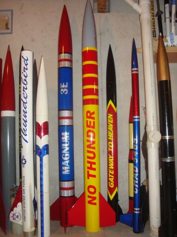
1. The components were purchased from Performance Hobbies as a “TCB Thunder”. I had some credit with Ken from an order that didn’t pan out, I remembered the TCB Thunder as a large, simple, sport flyer from days of old and thought it would be a fun build. Thunder kit: https://www.rocketryonline.com/jimball/jimball/construction/TCB/default.htm. Mark M.'s Thunder (top photo) of which has flown at the Bong lots of times in lots of years: https://tripoliwisconsin.com/meierm1/june13-4.html. When the kit arrived, I could instantly see that this kit was No Thunder! A little bit different #1: TCB kits used a nosecone that was just slightly shorter and had a different base than the Loc PNC-5.38L; instead I received a Loc nosecone. The Thunder had one section of 48” airframe with no payload section; I got a standard Loc 42” airframe, 20” payload, a coupler and a bulkplate. The fins were too small to be Thunder fins; they were more like Thoy Falcon fins. No complaints here, as most or all of the replacement items would be considered upgrades; nevertheless, this was No Thunder!
2. My 3 year old son developed a fear of thunderstorms this summer after a strong storm moved through one night. For some time afterward, he would ask every night before going to bed: “No thunder, daddy?” He’s gotten over it, but still is occasionally concerned with thunderstorms. After hearing that phrase every night for several months, it seemed appropriate for use.
Purpose/Goal:
Though 5.5” cardboard rockets are probably my favorite size for high power sport flying, I had no intention of building No Thunder so soon, as I recently built a similarly sized Loc Magnum:https://www.rocketryforum.com/showthread.php?30930-Loc-Magnum-Build&highlight=Loc+Magnum+build. However, at MWP-X rocket buddy Preston sells me an AMW K500 Skidmark for a nice price. Alas, we have A little bit different #2: check out the bass-ackwards thrust curve on this thing: https://www.thrustcurve.org/simfilesearch.jsp?id=1329; it is literally backwards from a “normal” slightly erosive Bates grain thrust curve. That low initial thrust of 320 Newtons calls for unusual measures to keep a 7’ tall 5.5” rocket under 14.38lbs loaded with motor. Since the K500 weighs 6 lbs loaded, the goal is to create a completed model, ready-to-fly, under 8.38lbs. While the Magnum would probably do just fine on a calm day; I’m a big fan of at least a 5:1 thrust:weight ratio.
A little bit different #3: Fin Construction Part I
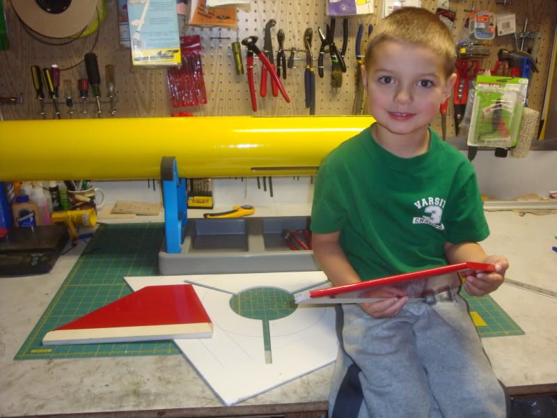
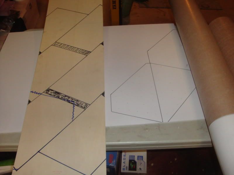
The fins supplied with the “Thunder” kit were very nice aircraft grade ply, yet the shape was both smaller than desired and different from the original Thunder design. This gave me an opportunity to redefine the fins. I decided to use the fin design from an old friend: a scratch built 5.5” x 8’ rocket called Hot Topic that I built in 2000. Only this time, I wanted to lighten the fins. In lieu of the ¼”’ply fins on Hot Topic, the No Thunder fins are each constructed of 5 parts: a 3/16” Gatorfoam core, 3/32” Lite ply laminated to each side of the core, and the leading and trailing edges are capped by 3/8” poplar dowels.
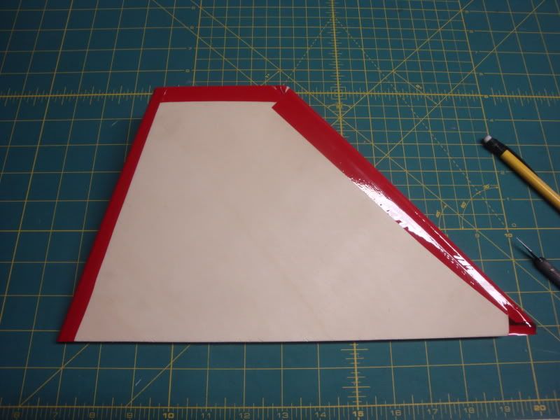
Here's a brief photo essay of their assembly. First up, a fin pattern is developed. 3/8" is removed from both the leading and trailing edges, as they will be capped with the 3/8" dowels. Trace pattern onto the Gatorfoam core and the lite ply sides. Grain direction doesn't exist for the foam, but matters greatly with the lite ply (of the 3 ply's, the outer two run the longer length of the sheet, or along the fin leading edges).
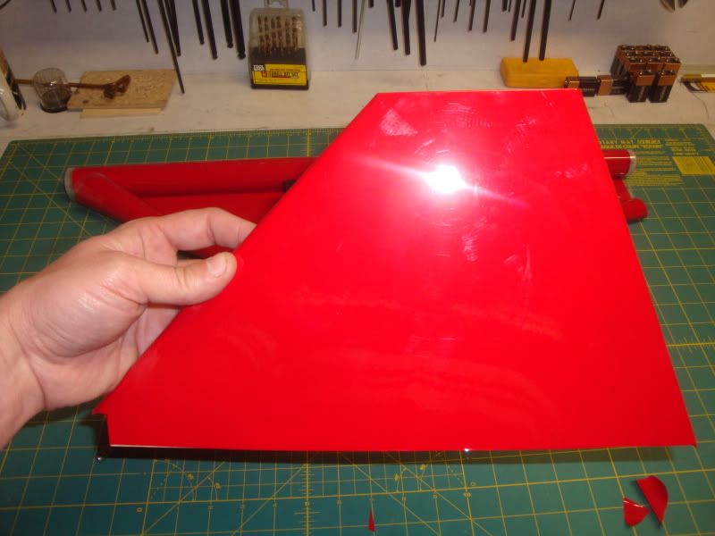
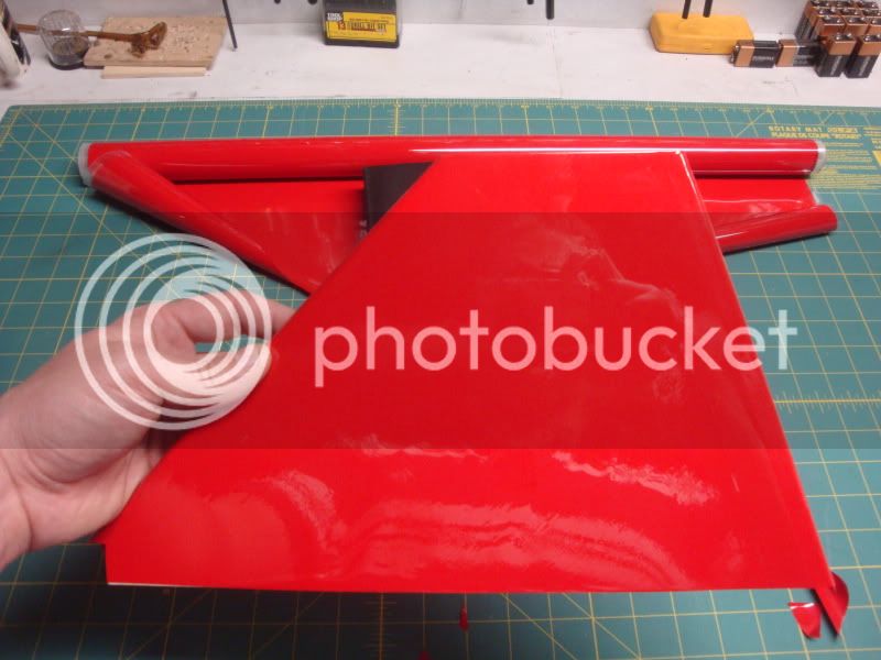
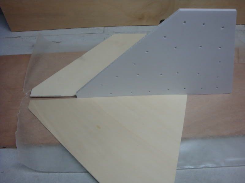
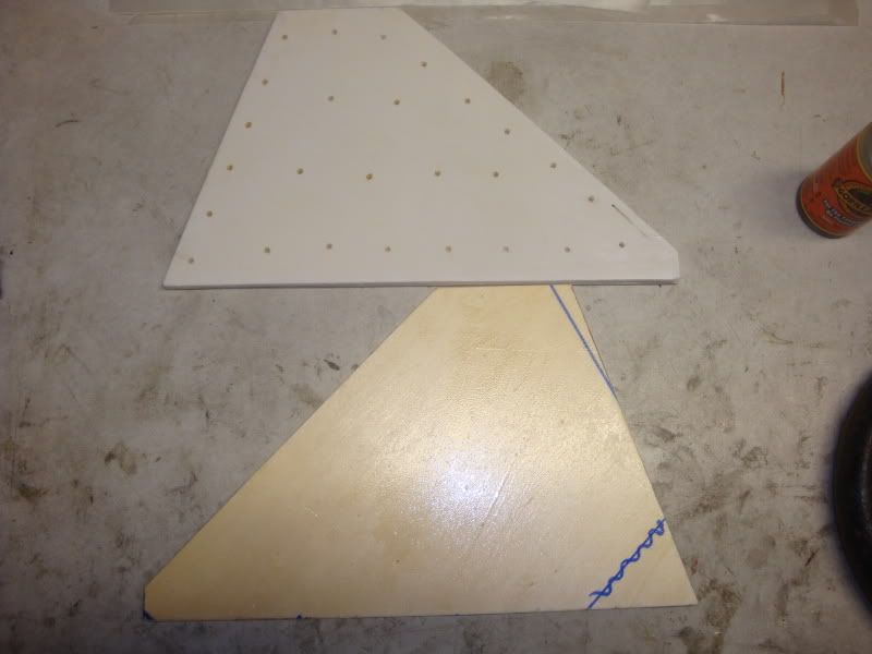
The pieces were cut out and returned to the workbench; and here's your sandwich. Flip up the ply sides and you get the idea. The small holes in the foam form "glue rivets" during the laminating process.
One side of the foam is wiped with a damp cloth, and a moderate amount of Gorilla Glue is applied to both surfaces. Note that the water reacts with the polyurethane glue which causes it to expand. The motor water involved, the greater the expansion.
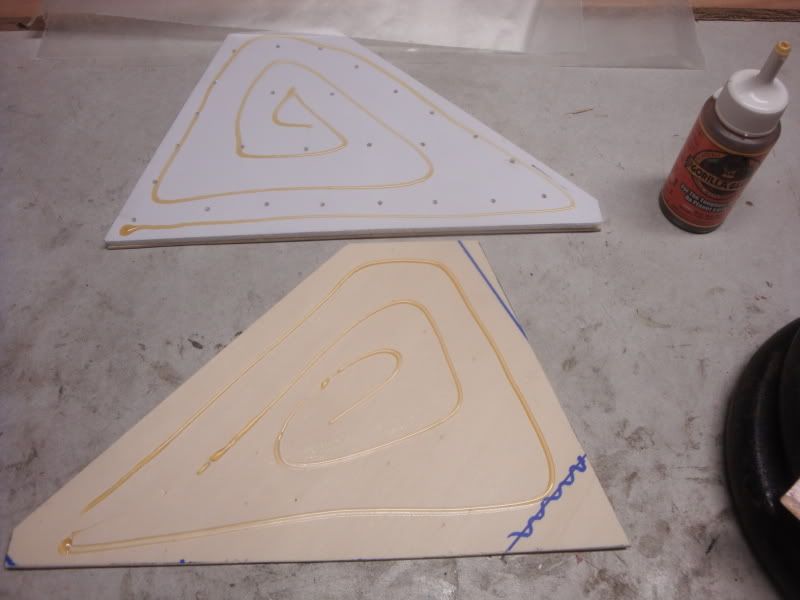
The pu glue is spread evenly until a uniform thin film is over each surface.
The same process is done to the other side of the fin, and both sides of the remaining fins. Masking tape is applied over the edges to make sure the laminations don't shift around, and the fins are stacked between two layers of heavy plywood and weighted down with ~100lbs. They cure for 36 hours before moving on.
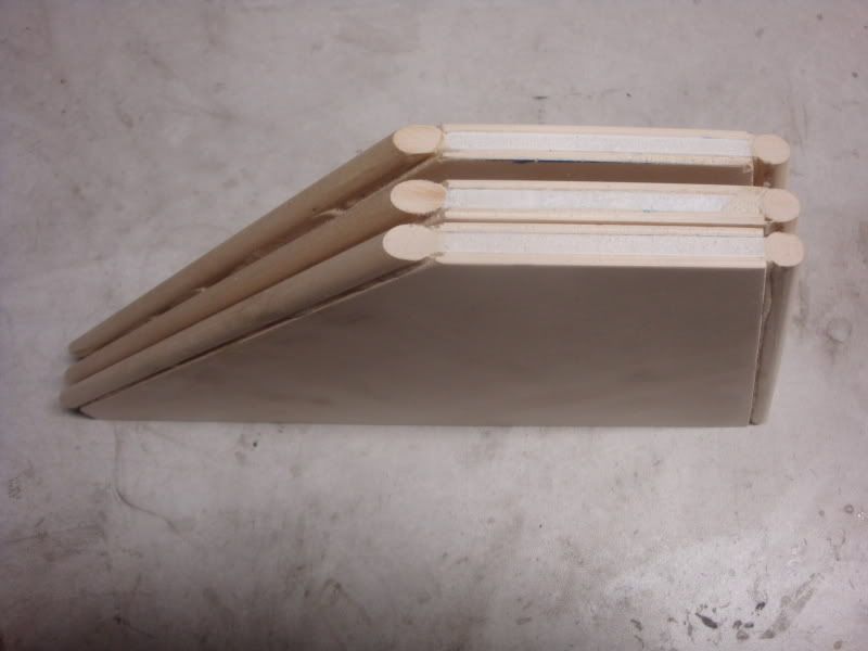
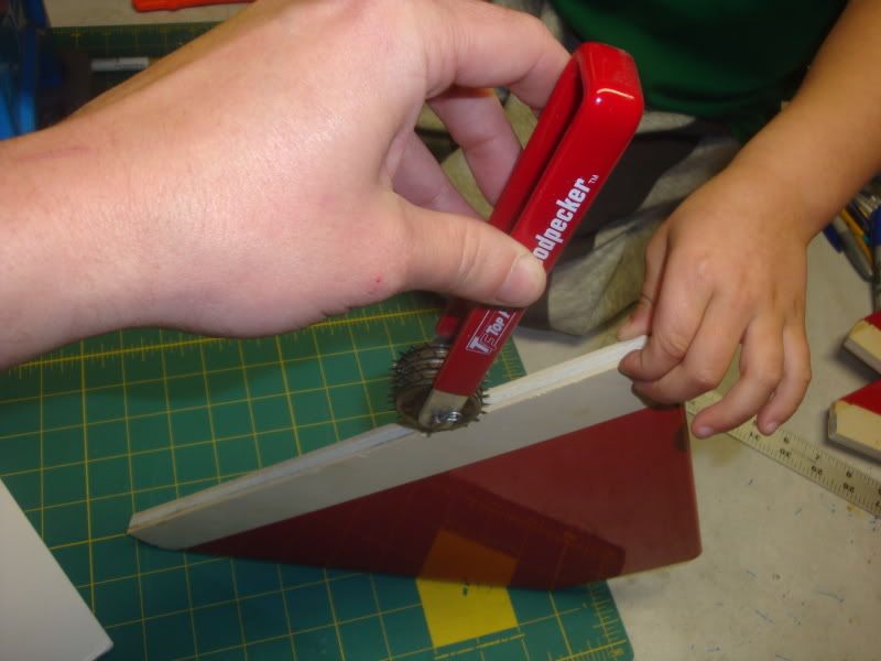
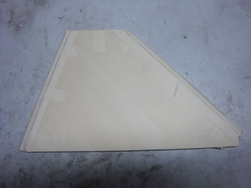
After the laminations have cured, 3/8" poplar dowels are cut slightly oversized for the leading and trailing edges. The leading and trailing edges are wiped with a damp cloth, and the dowels glued to the respective edges once again using Gorilla Glue. Masking tape holds the dowels in place and ensures any expanding glue stays where I want it. Back in the weighted press to dry for another 24 hours. Here's the assembled fins before removing tape:
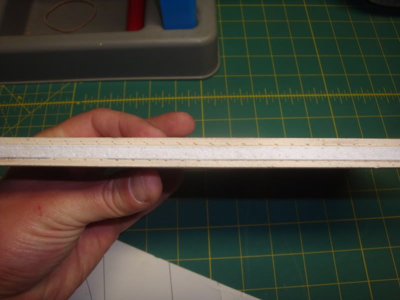
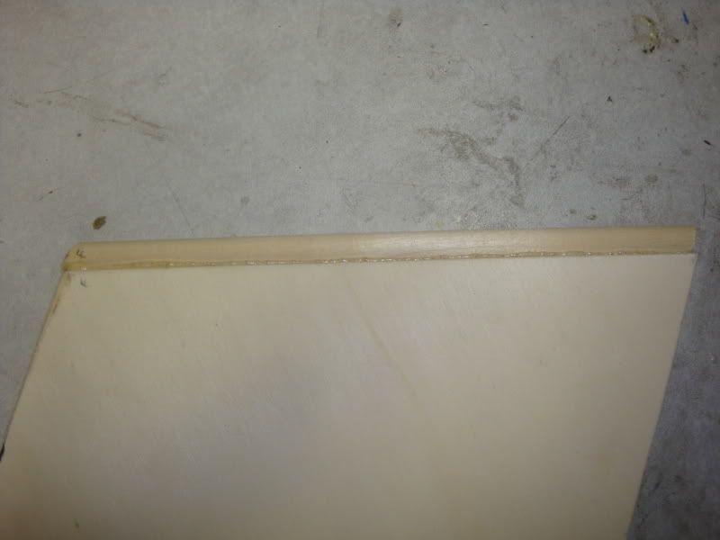
With the tape removed, you can see where the G-glue expanded around the dowl, yet didn't protrude beyond the plane of the fin sides.
That's all for now; I'll be back with A little bit different #4 and beyond shortly!
-Eric-
No Thunder: what’s in a name?
The name has a two-fold meaning:
1. The components were purchased from Performance Hobbies as a “TCB Thunder”. I had some credit with Ken from an order that didn’t pan out, I remembered the TCB Thunder as a large, simple, sport flyer from days of old and thought it would be a fun build. Thunder kit: https://www.rocketryonline.com/jimball/jimball/construction/TCB/default.htm. Mark M.'s Thunder (top photo) of which has flown at the Bong lots of times in lots of years: https://tripoliwisconsin.com/meierm1/june13-4.html. When the kit arrived, I could instantly see that this kit was No Thunder! A little bit different #1: TCB kits used a nosecone that was just slightly shorter and had a different base than the Loc PNC-5.38L; instead I received a Loc nosecone. The Thunder had one section of 48” airframe with no payload section; I got a standard Loc 42” airframe, 20” payload, a coupler and a bulkplate. The fins were too small to be Thunder fins; they were more like Thoy Falcon fins. No complaints here, as most or all of the replacement items would be considered upgrades; nevertheless, this was No Thunder!
2. My 3 year old son developed a fear of thunderstorms this summer after a strong storm moved through one night. For some time afterward, he would ask every night before going to bed: “No thunder, daddy?” He’s gotten over it, but still is occasionally concerned with thunderstorms. After hearing that phrase every night for several months, it seemed appropriate for use.
Purpose/Goal:
Though 5.5” cardboard rockets are probably my favorite size for high power sport flying, I had no intention of building No Thunder so soon, as I recently built a similarly sized Loc Magnum:https://www.rocketryforum.com/showthread.php?30930-Loc-Magnum-Build&highlight=Loc+Magnum+build. However, at MWP-X rocket buddy Preston sells me an AMW K500 Skidmark for a nice price. Alas, we have A little bit different #2: check out the bass-ackwards thrust curve on this thing: https://www.thrustcurve.org/simfilesearch.jsp?id=1329; it is literally backwards from a “normal” slightly erosive Bates grain thrust curve. That low initial thrust of 320 Newtons calls for unusual measures to keep a 7’ tall 5.5” rocket under 14.38lbs loaded with motor. Since the K500 weighs 6 lbs loaded, the goal is to create a completed model, ready-to-fly, under 8.38lbs. While the Magnum would probably do just fine on a calm day; I’m a big fan of at least a 5:1 thrust:weight ratio.
A little bit different #3: Fin Construction Part I
The fins supplied with the “Thunder” kit were very nice aircraft grade ply, yet the shape was both smaller than desired and different from the original Thunder design. This gave me an opportunity to redefine the fins. I decided to use the fin design from an old friend: a scratch built 5.5” x 8’ rocket called Hot Topic that I built in 2000. Only this time, I wanted to lighten the fins. In lieu of the ¼”’ply fins on Hot Topic, the No Thunder fins are each constructed of 5 parts: a 3/16” Gatorfoam core, 3/32” Lite ply laminated to each side of the core, and the leading and trailing edges are capped by 3/8” poplar dowels.
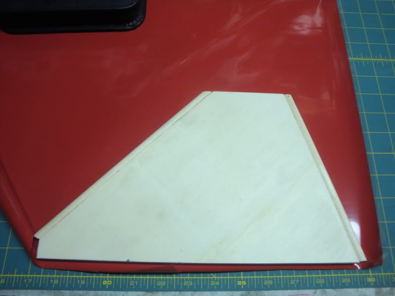
Here's a brief photo essay of their assembly. First up, a fin pattern is developed. 3/8" is removed from both the leading and trailing edges, as they will be capped with the 3/8" dowels. Trace pattern onto the Gatorfoam core and the lite ply sides. Grain direction doesn't exist for the foam, but matters greatly with the lite ply (of the 3 ply's, the outer two run the longer length of the sheet, or along the fin leading edges).
The pieces were cut out and returned to the workbench; and here's your sandwich. Flip up the ply sides and you get the idea. The small holes in the foam form "glue rivets" during the laminating process.
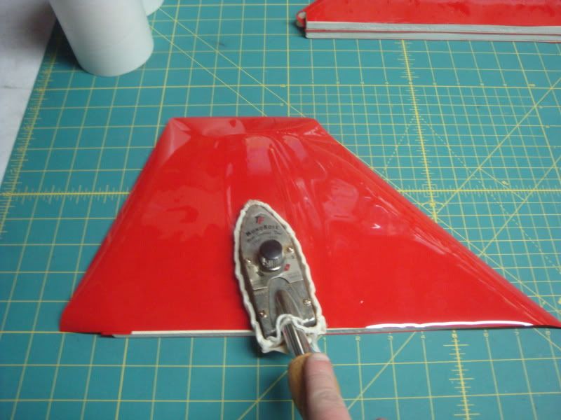
One side of the foam is wiped with a damp cloth, and a moderate amount of Gorilla Glue is applied to both surfaces. Note that the water reacts with the polyurethane glue which causes it to expand. The motor water involved, the greater the expansion.
The pu glue is spread evenly until a uniform thin film is over each surface.
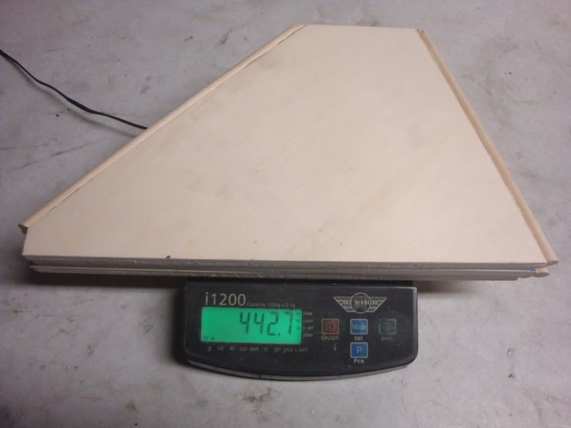
The same process is done to the other side of the fin, and both sides of the remaining fins. Masking tape is applied over the edges to make sure the laminations don't shift around, and the fins are stacked between two layers of heavy plywood and weighted down with ~100lbs. They cure for 36 hours before moving on.
After the laminations have cured, 3/8" poplar dowels are cut slightly oversized for the leading and trailing edges. The leading and trailing edges are wiped with a damp cloth, and the dowels glued to the respective edges once again using Gorilla Glue. Masking tape holds the dowels in place and ensures any expanding glue stays where I want it. Back in the weighted press to dry for another 24 hours. Here's the assembled fins before removing tape:
With the tape removed, you can see where the G-glue expanded around the dowl, yet didn't protrude beyond the plane of the fin sides.
That's all for now; I'll be back with A little bit different #4 and beyond shortly!
-Eric-
Last edited: