3D Printing MK3S Lack Enclosure - Remix

The Rocketry Forum

Help Support The Rocketry Forum:

This site may earn a commission from merchant affiliate links, including eBay, Amazon, and others.

Tobor

Get your peanuts....
TRF Supporter
Joined
Oct 8, 2016
Messages
2,834
Reaction score
1,210
Okay, this is my take on creating a home for my Prusa.

List of sub-projects I would like to incorporate in this build;
*PVC Riser for the enclosure.
*Heated dry box with feeder tube.
*OctoPrint controller with webcam integration.
*OctoDash Touch Console with dimmable LED lighting and fan control.
*Intake fan(s) with removable dust filter.
*Modular connectors to/from Mk3S to aid in servicing printer and devices.
*Tool drawer with "Soft Close" slides.
*Smoke detector with emergency power off control of MK3S.

I will attempt to keep things organized as best I can. I hope to include enough detail for others to replicate any part of this project. So please feel free to ask questions or make requests for greater detail if something I have posted is unclear.
 
Lack Enclosure (Phase 1)

I have been working on and off, for the past week, finalizing the riser for the enclosure. The threaded PVC fittings I purchased will not work as intended due to my ignorance, that being the threads of plumbing parts are tapered threads, not parallel threads. The end result is that any male/female pair of threads never use the full length of the threads. Of course this makes perfect sense for plumbing...

So, to help facilitate leveling of the enclosure I will use PVC plugs, or PVC reducer bushings, with a wooden dowels inserted into the hollow of the plug and use swiveling furniture leveling feet for adjustments.

The PVC plug
white-charlotte-pipe-pvc-fittings-pvc.jpg

PVC Reducer Bushing
charlotte-pipe-bushings-pvc.jpg


These are the leveling feet I have ordered from Amazon
61PYVQmaI%2BL.__AC_SX300_SY300_QL70_ML2_.jpg


Once the leveling feet arrive I can begin assembling the riser.

--- Update 06.11.21 ---

This project made it off the drawing board after a few interruptions and some design changes..

Note: This line would be the perfect spot to insert a sketch of the PVC riser, but my initial renderings are not fit for public consumption. Cleaner sketches will be inserted soon.

Starting with the PVC fittings...

PVC Riser Parts_Markups-Small.jpg

The red arrow points to an imposter that snuck it's way into my purchase. Of course my neighborhood Home Depot was out of stock upon my return for exchange. Thankfully, another HD 20 minutes away had the plug I was looking for.

The PVC couplers, red box, were eliminated from the design , so they will returned this weekend.

Plug Drill Guide

PVC Plug Drill Guide_03-Small.jpg

I printed a guide so the starter holes I needed to drill in the PVC plugs would be accurately centered.

More 3D parts with some associated hardware

PVC Plugs, Hardware and 3D printed Parts-Small.jpg

The square printed parts: These are spacers that sit between the end of the Lack table legs and the PVC plugs that will be bolted to them. Although it is hard to see in the picture, there are two different sets of spacers. A thin set of two (1/8" in height) spacers are used with the 4-way PVC fittings, and the other set of two (1/4" in height) spacers are for the 3-way PVC fittings

========================
Note: Okay, I discovered an error while posting this update. The tall spacers are 1/8 inch too tall.... :(
In Fusion 360, I modeled the tall spacer from the thin spacer and added 0.25 inches to it's height, rather then setting it's total height to 0.25 inches. So..... since the spacers have already been epoxied into place, have to print out a set of (2x) 0.125 inch shims for the 1/8 inch spacers... Oh joy.
========================

The other printed parts: The flanged prints (w/ the button caps) are the covers that will protect the threaded portion of the leveling feet when the assembled riser gets filled with sand.

Some assembly required

Lack Leg after Tee Nut Fitting-Small.jpg
I used the square spacers to locate and drill the starter holes for the 1/4-20 Tee Nuts. Then I drilled the starter holes to accept the tee nuts and test fitted tee nuts.

Lack Leg, Epoxy & Tee Nut-Small.jpg
Next I coated the bottom of the legs with Aeropoxy and tapped the tee nuts into place with a hammer.

3D printed Spacers Attached-Small.jpg
Then I placed the spacers onto there respective locations and bolted them down. After that I flipped the table right side up placed it on the kitchen floor. Then I placed about 35 lbs of weight on top of the table to load up the glued parts until the epoxy cured.

1st Section of Riser Assembled & Fitted-Small.jpg
After the epoxy was fully cured I cut a piece of PVC tubing to length (17-7/32") and cemented a 3-way and a 4-way fitting to each end of the cut tube. Next, keeping my fingers crossed, I test fitted the assembly. Came out a-okay. :)

1st Section of Riser (Closer View)-Small.jpg
Close up view.

I've run out of time for posting this update. So, that's all for the moment.

--- Update 06.14.21 ---


PVC Riser Frame assembled


Lower plugs fitted for leveling feet.


Phase 1 of this project is now complete
 
Last edited:
Lack Enclosure (Phase 2) - 06.18.21

This phase of the project will incorporate 18x18 floor tiles to increase the inertial mass of the enclosure and help reduce the printers sound/vibration transmissions.

Materials used:
5.2mm x 2' x 4' Plywood underlayment (Link)
5/8" thick MDF (Scrap piece)
18" x 18" Floor Tiles

I started by removing the legs from the table top and placed it on the plywood along two edges to reduce the number of cuts. I used a pen to trace out the other two sides of the table. Next, using a framing square and utility knife I cut along the traces (one side at a time) making several passes until my part was free. Then I marked out the centers in each corner of my plywood piece and drilled out oversized holes to ensure I didn't have alignment issues with the table leg dowel screws. After I was sure all was fine I applied Titebond III to one side of the plywood, first around the perimeter and then a zigzag in the field. Repeated this on the bottom side of the table and then laid the plywood in place. Lastly, I added weights on top off the plywood until glue was dry.

Plywood Reinforcement (Table Bottom)
Lack Bottom Plywood Reinforcement-Small.jpg

Now for the top side of the table.

After placing masking tape near each corner, I marked out a square 18.25" x18.25" and used my trusty framing square and utility knife and cut out the center of the table. I had to apply some force to pry my cutout from the paper corrugation that is used to strengthen the table top.

Lack Table Delidded
Lack Core-Small.jpg

Next up, I used my utility knife to cut through the corrugation along the perimeter of my cutout and then removed all that corrugation from the field.
Using a fresh utility blade, I scraped the field to remove any bits of paper left behind.

Table Top Corrugation Removed.
Lack Table Decored-Small.jpg

I used a 30° aluminum triangle to help mark out guide lines for the pieces I would be gluing in place. Order of installation: 18" square of 5.2mm plywood, 18" square of 5/8" MDF and 3x 18" square floor tiles.

Marked Out Guide Lines
Lack Table Core Markup-Small.jpg

I used Titebond III to glue in plywood and MDF squares.

Plywood (already glued in) & MDF fillers
Lack Table MDF Insert-Small.jpg

Using GE 100% silicone adhesive, I glued in each of the 3 tiles, applying the adhesive using the pattern shown in the picture below.

Silicone Glue Pattern
Lack Table Tile Glue Pattern-Small.jpg


3rd Tile Glued In
Lack Table Tile Installation Complete-Small.jpg
 
Last edited:
Heated dry box

I got the idea for my feeder/dry box from the following YT video


I ordered a refurb unit on Amazon. It arrived with a nice crack in one of the drying trays. At first I was okay with the defect as I was going to hack most of the trays anyway. But, two days ago I stumbled upon a similar dehydrator with taller trays (Link).
Sunix Food Dehydrator.jpg

Sunix unit should arrive today (Flexzion is being returned). The taller walls will make it much easier to install a filament port.

I designed (more like over engineered) a rotating filament spool holder that will sit inside the dryer.

It looks like this.
Rotating Spool holder - Complete-Small.jpg

It is designed around using (10) 3/8" PTFE ball bearings from McMaster-Carr.

Btw, Amazon prices for Prusament are ridiculous atm, so I purchased some Hatchbox PETG in Black.
HatchBox PETG - Black-Small.jpg
I will be using PETG for most/all the printed parts used in this project.
 
Last edited:
OctoPrint

Although OctoPrint & OctoDash will be hosted on the same hardware, a Raspberry Pi 4 (4GB version), I wanted to keep my ramblings of each app and related hardware separate.

IMO, the one negative shared by all versions of the Raspberry PI, R-Pi for short, is the microSD card form factor they use for the OS and mass storage . SD cards are not, and never have been, designed to withstand the rigors of constant read/write operations that all OS's need to perform in order to function.

Thankfully, most versions of the R-Pi can boot and operate solely on a HDD or SSD. That is, until the R-Pi 4 hit the market. For some reason the Raspberry Pi Foundation decided to release the R-Pi 4 without the ability to boot from anything other than a microSD card. Admittedly, that feature was on the development roadmap for the R-Pi 4 but, the foundation sorely underestimated the market demand for alternate boot mediums. And it took the foundation over a year to release a firmware update with alternate boot sources enabled.

Anyhoot, booting from an SSD is a now a thing and I will be employing that feature in this project.

I will be using an old 120GB Samsung 840 Pro SSD as my boot device. To make use of the 840 Pro, I had originally planned on using the Geekworm X832 SATA adapter. It's a pricey option considering the other items needed to complete the setup, like the Geekworm X735 and a 12V 3A power supply, but it works well.

The X832 (click image to enlarge)
Geekworm X832.jpg

Fortunately for me and other R-Pi 4 owners, 52Pi recently released the DeskPi Pro enclosure. The DeskPi Pro gives the R-Pi 4 a form factor that is truly suitable for use as a desktop PC. And, the $60 asking price of the DeskPi Pro includes an elegant USB to SATA solution, active CPU cooler, two full size HDMI ports, two extra USB 2.0 ports on the front panel, safe shutdown and reset via the front panel power switch and a QC 3.0 power supply.

The DeskPi Pro (click image to enlarge)
DeskPi.jpg
I will be placing an order for a DeskPi Pro as soon as complete this post.... :)
 
Last edited:
Heated dry box (Continued)

Earlier this week, I designed a port that will allow the dried filament to pass through the dehydrator and into a Capricorn bowden tube, which feeds the filament through the upper table and into the enclosure where the MK3S will reside.

Filament Port
Spool Feeder Render - 01.jpg

Bowden Tube Kit (Link)
Capricorn Premium Bowden Tubing Kit.jpg

I think I will print the port in PLA. If it fails at some point then I just reprint in PETG.
 
Last edited:
Update:

OctoPrint

Although OctoPrint & OctoDash will be hosted on the same hardware, a Raspberry Pi 4 (4GB version), I wanted to keep my ramblings of each app and related hardware separate.

IMO, the one negative shared by all versions of the Raspberry PI, R-Pi for short, is the microSD card form factor they use for the OS and mass storage . SD cards are not, and never have been, designed to withstand the rigors of constant read/write operations that all OS's need to perform in order to function.

Thankfully, most versions of the R-Pi can boot and operate solely on a HDD or SSD. That is, until the R-Pi 4 hit the market. For some reason the Raspberry Pi Foundation decided to release the R-Pi 4 without the ability to boot from anything other than a microSD card. Admittedly, that feature was on the development roadmap for the R-Pi 4 but, the foundation sorely underestimated the market demand for alternate boot mediums. And it took the foundation over a year to release a firmware update with alternate boot sources enabled.

Anyhoot, booting from an SSD is a now a thing and I will be employing that feature in this project.

I will be using an old 120GB Samsung 840 Pro SSD as my boot device. To make use of the 840 Pro, I had originally planned on using the Geekworm X832 SATA adapter. It's a pricey option considering the other items needed to complete the setup, like the Geekworm X735 and a 12V 3A power supply, but it works well.

The X832 (click image to enlarge)
View attachment 469332

Fortunately for me and other R-Pi 4 owners, 52Pi recently released the DeskPi Pro enclosure. The DeskPi Pro gives the R-Pi 4 a form factor that is truly suitable for use as a desktop PC. And, the $60 asking price of the DeskPi Pro includes an elegant USB to SATA solution, active CPU cooler, two full size HDMI ports, two extra USB 2.0 ports on the front panel, safe shutdown and reset via the front panel power switch and a QC 3.0 power supply.

The DeskPi Pro (click image to enlarge)
View attachment 469333
I will be placing an order for a DeskPi Pro as soon as complete this post.... :)

As much as I really like the DeskPi Pro, I never ordered it. I did a bit more research and discovered the first run of DeskPi's had a serious bug in the USB to SATA adapter. 52Pi responded promptly with a revision, using a different USB to SATA bridge. That bridge however is markedly slower then the original chip, so I decided against clicking the yellow "Buy Now" button.

Digging around the Net turned up many positive reviews of the Argon One M.2 addon kit. As it is specifically designed for use with an R-Pi 4, compatibility is a non-issue. And at $20, it is a really good deal. Since I do not own an Argon One case, I decided to design my own case that will house all the nerdy bits I'd like to have in a rad R-Pi box.

OctoCase-Small.jpg

If I remember correctly, the 2st draft of the case design measures 137mm x 99mm x 42mm (5.393in x 3.897in x 1.653in).
The top and bottom will be printed in Black PETG and the middle section in Silver PLA.

List of parts:
> R-Pi 4 (4GB)
> GeeekPi R-Pi 4 Aluminum Armor Lite Heatsink w/ PWM Fan (Link)
> Argon One M.2 addon board (Link)
> Samsung 860 EVO SATA M.2 (250GB) (Link)
> M.2 2280mm Heatsink (Link)
> GeekPi 0.96 Inch OLED 128x64 White Display Module (Link)
> Noctua NF-A4x10 (40x40x10) 5V case fan (Link)
> Bulgin Cloned 16mm Momentary Black Push Button Switch w/ Blue LED (Link)
> Female HDMI Type A to Male Micro-HDMI adapter (4K rated) (Link)

I already have the R-Pi and I purchased the M.2 SSD yesterday at Micro Center. The rest of the parts are arriving tomorrow. Then I can take final measurements and adjust the case design accordingly.

This is going to be a lot of fun...

Update: 07.10.21

The parts arrived Friday afternoon.
OctoCase Parts-Small.jpg

I started printing the case pieces this evening. Using 0.20 (Quality) settings for both PETG and PLA. Prints are going to take awhile...
And here is an animation of my case design.
View attachment OctoCase.mp4


Update: 07.06.21

Making progress but I've sorta hit a wall. And that wall is called Python, as in the programming language. I am NOT a coder.... but I will muddle through

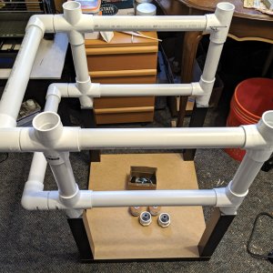
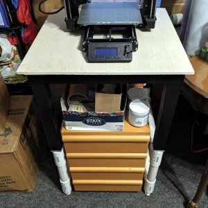
Anyhoot, some pics of the current state of things.

OctoCase Current Progress_01-Small.jpg

OctoCase Current Progress_02-Small.jpg

Another Update: 07.28.21

In order to address all the extra power that will be required to operate the additions/mods to this project, I recently pulled the trigger on this little beauty...

EVGA 550-GM SFX PSU (Link)
EVGA 550GM PSU-01-Small.jpg

EVGA 550GM PSU-02-Small.jpg


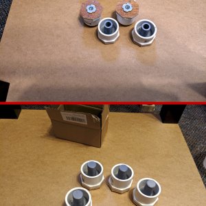
And yes, it's a PC PSU. 1st pic demonstrates the small size of the SFX form factor compared to a standard size ATX12 PSU.

The reasons for going this route are many, but the primary reason is highly stable power and lots of it. And that power comes in three voltages, +3.3V @ 20A, +5V @ 20A, +12V @ 45.8A. Along with all that power, a quality PSU like the 550 GM employs many forms of protection including OTP, PFC, UVP, OVP, OCP OPP & SCP.

Although it is more expensive then a Meanwell power supply that I've seen many 3D printer owners use, it is much more versatile and robust.

Hopefully I make time to post more info soon, but that's all for now.

Update: 08.05.21

Well, I still have not finalized anything in the way of a power distribution layout. But it is coming.

In regards to coding in Python, well... it still sucks. In a nutshell, programming is the art of rearranging all your neural pathways in order to think like a computer.
Here is an example:

The python script for the OLED status display would run fine in the Thonny IDE but would throw an error when the R-Pi OS would launch the script.
The error looks like this;

Python:
pi@octopi:~ $ /usr/bin/python3 /home/pi/pyscripts/Stats_Display/OLED_stats.py
Traceback (most recent call last):
  File "/home/pi/pyscripts/Stats_Display/OLED_stats.py", line 103, in <module>
    font = ImageFont.truetype("./PixelOperator.ttf", 16)
  File "/usr/lib/python3/dist-packages/PIL/ImageFont.py", line 280, in truetype
    return FreeTypeFont(font, size, index, encoding, layout_engine)
  File "/usr/lib/python3/dist-packages/PIL/ImageFont.py", line 145, in __init__
    layout_engine=layout_engine)
OSError: cannot open resource
pi@octopi:~ $

I spent half the day trying to track down the meaning of all that "stuff" on Reddit, StackOverflow,GitHub, etc... When I was about to give up for the day, a thought floated to surface of my consciousness stating that I need to be explicit.

And the thought was right! Basically, that mumbo jumbo statement above, when translated into human form means:
"Hey, what the heck? I cannot find anything that matches your PixelOperator.ttf font, so fix it!"

Python, as setup in OctoPi, cannot make sense of ./ (Look in the place where I am stored) in the line "font = ImageFont.truetype("./PixelOperator.ttf", 16)"
So, after changing that line in the Python script to read "font = ImageFont.truetype("/home/pi/pyscripts/Stats_Display/PixelOperator.ttf", 16)", my display came to life, finally.

Now I just need to get the other two Python scripts that I am working on to run.... Later, much later......

In other news, today I did manage to finish wiring up the Noctua fan and getting that installed. Pics will happen after I work out power routing from the EVGA PSU. And speaking of PSU's, I completed drawing up it's mounting bracket in Fusion 360. It will be printed in HatchBox Red PETG.

EVGA PSU Mounting Bracket-01.jpg
EVGA_PSU_Mounting_Bracket_Remix-01a_2021-Aug-05_03-12-00AM-000_CustomizedView3911826498.png

Till next time.
 
Last edited:
Okay, another update. (Continuation of post #12)

But first, I would like to apologize for how fractured this thread has become. I tried to get an exception to the post locking rule for this thread but that request was denied. Oh well...

I didn't have much time over the past weekend to work on Prusa projects. Instead I had to work on rebuilding two of my old BOINC crunchers for my church. First system is for one of the senior ladies who's WinXp machine gave up the ghost some time ago and her fixed income cannot cover a replacement. The other system will be used as a secondary TrueNAS box for the church's servers.

Anyhoot, let's see some pics!

My mostly functional OctoPi box
OctoCase Operational [Edited]-Small.jpg

Locking down my Lack Enclosure
Prusa Corner Bracket Mod-Small.jpg

Prusa's remix of the Lack enclosure is nice but, it is not perfect. With their rendition, each leg of the enclosure's upper section receives a cone shaped pin that has been affixed to the lower section. The issue is their design relies solely on gravity and those pins to keep the upper section in place. That concept won't survive in my workshop. So, before I printed those parts I modified them to allow using Du-Bro #6 x 3/4" socket head sheet metal screws to lock each leg to it's corresponding pin. This little mod turned out quite well me thinks.

<EOL>

So finally another update:

First up, the PSU mounting bracket.
EVGA Mounting Bracket-Small.jpg

I printed that up last week. If you look closely, you will see that the bracket's face has a slight curve to it. I had set the tolerances a little tight but when it gets attached to the plywood panel, it won't be an issue.

Next up, the power distribution block.

Parts from DigiKey
PSU Block - Parts-Small.jpg

Pref Board build - Top. 1st column = 3.3V lines, 2nd column = 5V lines. there will be a 3rd column @12V
PSU Block - Pref Board (Top)-Small.jpg

Pref Board build - Bottom
PSU Block - Pref Board (Bottom)-Small.jpg

Test fit of enclosure.
PSU Block - Test Fit-Small.jpg

Here is the pinout representing the 24-pin connector from the PSU.

1630125764138.jpeg
I will be using pins 2 & 3 (+3.3V), 4 & 5 (+5V) and 11 & 24 (+12V). I may also use pins 16 & 17 via a latching switch for PS-ON (Power Supply On).

Till next time.
 
Last edited:
Next time is now.... (Continuation of Post #17) Update:

Last night my lost package found itself and arrived at my doorstep.

In other, less dramatic news, I've made progress on the Filament drybox.

Rotating Spool Holder - PETG (17 hour print)
Spool Holder - Complete-Small.jpg

Spool Holder Test Fit
Spool Holder - Test Fit-Small.jpg

3 layers of trays roughed in
Spool Holder - Rough In-Small_a.jpg

It still needs some tweaking and a few small parts to print before it is finished.

To be continued...

Update 09.06.21
More progress!

First up is the completed DryBox in action
Headed DryBox - Complete-Small.jpg


Next, a render of my Prusa Black PSU Mounting Brackets
Prusa_Black_PSU_Mount Render.png

And... my first failed print :(
Black PSU Mount - Failed Print.jpg

The print failed because I've been sloppy with handling my spools of filament. I inadvertently allowed the cut end to get under another winding and did not notice the issue. Print started out fine last evening, but after I went to bed (It was an 11 hour print) the tangled filament started binding and at some point it was tight enough to lift the printer and allow it to move! I am glad I had changed my mind about filament choice as my original intent was to use Hatchbox Red PETG (PETG had the same unnoticed issue), not the Prusament Silver PLA. A much cheaper mistake with PLA.

Prusa Black PSU Mounting Brackets - 2nd attempt
Success!
Prusa Black PSU Mount-Small.jpg

Also, early last week I finished work on the power distro block
PSU Block - Complete-Small.jpg

That's all for now.

It's that time again.... Update 09.12.21

I had some extra time off from work last week, as they observe all national holidays (Monday being Labor Day), and all Jewish holidays (Monday, Tuesday & Wednesday being Rosh Hashana).

Used up that time on two trips to Home Depot, two redesigns of the upper bracket of the Black PSU mount (due to PEBCAK errors), some use of my circular saw along with my router, some spray paint and a lot of time using my drill and trusty old screwdriver. Then last evening and this morning, my soldering station got all the action.

Final result....
PSU Relocation_Complete-Small.jpg

So, what's left on the project list? Funny you should ask....

*Print an adjustable arm for Arducam B0176 camera
*Purchase and install LED lighting
*Purchase OctoDash touchscreen (5" or 7") and design an adjustable mount for it
*Wire up tails for all the above (plus the R-Pi) to power them via the EVGA PSU
*Purchase sheet glass for the enclosure panels & doors
*Work out the details for "Emergency Shutdown" mode via smoke detector
*Maybe convert a 5 year old laptop with busted screen into a Spaghetti Detective server using their open source software.
*plus, anything else that has slipped my mind....

Till next time.

Okay, so like I have another update! 09.13.21 (Technically it's the 14'th but I haven't gone to bed yet...)

A new addition arrived today....
1631602345348.jpeg

EVICIV 7" Touch Screen. I was surprised to see all the accessories that were bundled with this monitor. I have already started designing a case for it.

Next update will have it's own post as I have just reached the 10 picture limit.

See y'all soon.
 
Last edited:
Nice work, I'm watching with considerable interest. I have a working near-stock MK3S, an unassembled Lack table and an RP3+ dev kit that need to be integrated. I like the idea of using a PC PSU with some DC distribution buses.
 
(Continuation of Post #20) Update:

And the EVICIV case design is finished
OctoDash EVICIV Display Case_01.png
OctoDash EVICIV Display Case_02.png
OctoDash EVICIV Display Case_03.png
All 6 parts will be printed in PETG.

I decided against making the mounting arm adjustable as it did not seem worth the effort to accommodate. The case will be mounted to the top front edge of the enclosure.

Here forthwith is another update (09.22.21)

The touchscreen case is complete
EVICIV Toucch Screen Installed-Small.jpg
The print revealed a few small errors in my design and my manual corrections were not very subtle. I'll probably reprint the cover at some point (yeah, right.) but the case is usable in it's current state.

Up next is the camera mount. I've settled on using this design by Sneakes along with this mod from Adrian Carpenter.

Chow for now.

Ta-da.... Update 09.26.21

The camera mount is mostly complete for now and includes one new simple part I designed and a remix of the camera housing.

Here is the housing remix
RaspiCam Housing Remix-Small.jpg

The housing was remixed to accommodate the Arducam (B0176) Auto Focus Camera and (B0091) CSI-to-HDMI Extension kit.

Camera mounted to HDMI module (Top) and 2nd HDMI module (Bottom)
Arducam (B0176) Camera + (B0091) CSI-to-HDMI Extension kit-Small.jpg

And here is the articulating arm installed
Articulating Camera Arm-Small.jpg

The new part I designed is the outside corner bracket that attaches the arm to the Lack enclosure.

Today I also learned how to configure the Linux Systemd daemon to start my Python scripts for the status display and power button. This was required because the "Autostart Folder" I originally used only works with the GUI desktop. As OctoDash only runs in Linux CLI mode, I had to find a way to run the scripts in that mode.

Til next time.

Update 10.10.21

Well, I've had my first mishap with my MK3S.

Last Monday I was trying to print a switch plate in PLA for the front of the Lack enclosure but having trouble with the print peeling off the print bed half way through the print. After my third attempt, I noticed some black residue on the X-axis's lower bearing rod. When I cleaned off the residue I saw that the rod had scoring (approx 1/8 " wide) across most of it's length. So the linear bearing has blown out. Damn!

While searching the Net for Misumi LMU8 Linear Bearings I discovered that Misumi is headquartered In Schaumburg, IL., about an hour drive from me and their manufacturing plant is 40 minutes away. Yesterday I placed an order for 10x LMU8 bearings for local pickup. I will be injecting Super Lube into all the linear bearings from now on.

I'll post an update when I get the MK3S torn down.
 
Last edited:
Update 10.10.21

Well, I've had my first mishap with my MK3S.

Last Monday I was trying to print a switch plate in PLA for the front of the Lack enclosure but having trouble with the print peeling off the print bed half way through the print. After my third attempt, I noticed some black residue on the X-axis's lower bearing rod. When I cleaned off the residue I saw that the rod had scoring (approx 1/8 " wide) across most of it's length. So the linear bearing has blown out. Damn!

While searching the Net for Misumi LMU8 Linear Bearings I discovered that Misumi is headquartered In Schaumburg, IL., about an hour drive from me and their manufacturing plant is 40 minutes away. Yesterday I placed an order for 10x LMU8 bearings for local pickup. I will be injecting Super Lube into all the linear bearings from now on.

I'll post an update when I get the MK3S torn down.

Oooops,
I completely forgot about posting an update to the above....

Update 10.27.21

Well, the MK3S is repaired and functioning normally again. I was able to realign the lower bearing rod such that the scoring marks will run in-between the linear bearing races. Also replaced one bearing on the Y-Axis. All linear bearings were injected with Super Lube using [this grease injector]. It worked like a charm.

During reassembly of the X-Axis I noticed some front to back play with the printhead. Closer inspection revealed a problem with the X-carriage-back plate. The back plate was not closing enough to fully capture the lower (single) linear bearing, allowing the printhead to pivot forward approx. 2mm. I could not identify anything that would keep the X-carriage-back from properly capturing the bearing. Apparently this condition has existed since the first build of the MK3S...

My solution involved applying a small strip of electrical tape, 3 layers thick, to the inside "cup" of the X-carriage-back that receives the linear bearing. Then I slowly tightened the bottom cap screw until all the play in the printhead was gone. Problem solved. I guess I should print a proper shim to replace the tape at some point in the future...........
 
Last edited:
Update 10.27.21_Part II

Yesterday I completed another mod to the Lack enclosure, 2 front mounted power switches. First switch controls power to the R-Pi and 7" display. 2nd switch controls power to the Prusa MK3S+. To keep me safe, by not having 120V AC runs inside the structure of the Lack enclosure, I used a 4-Channel relay board controlled by the front mounted switches to manage the AC voltages.

Project pics with short descriptions. If anyone would like more detailed info, please post your questions.

ELEGOO 4-CH 5V Relay Module (Link) & My case design for it
Relay & Enclosure-Small.jpg


Rewire of MK3S+ PSU power switch
Power Switch Mods - Prusa PSU_Large.jpg


MK3S PSU wired to Relay Ch-1
Power Switch Mods - Relay-Small.jpg


Added XT-30 connector to Power Distro Block (Post #20) for 5V Standby
Power Switch Mods - 5V Standby-Small.jpg


Completed wire harnesses for Sw #1, Sw #2 and R-Pi power
Power Switch Mods - Switch Harnesses_A-Small.jpg


Switch harnesses installed
Power Switch Mods - Harnesses Attached_A-Small.jpg


Wiring completed (Dress-in at a future date)
Power Switch Mods - Back panel-Small.jpg


And........ it works!!!
Power Switch Mods - Power On-Small.jpg


Wiring Diagram (For anyone interested)
Prusa Power Distro Diagram.jpg
 
Back
Top