Loc Custom 7.675" Saturn V

The Rocketry Forum

Help Support The Rocketry Forum:

This site may earn a commission from merchant affiliate links, including eBay, Amazon, and others.

ECayemberg

Well-Known Member
Joined
Jan 21, 2009
Messages
2,874
Reaction score
839
The following is a photo pictorial with brief descriptions of the assembly of the Loc Custom 7.67" Saturn V intended to guide the builder through the assembly process. It is expected that the builder of this kit has prior knowledge and experience with high power rocketry construction.

So welcome aboard, happy 50th Anniversary of the Apollo 11 flight, and enjoy the flight!

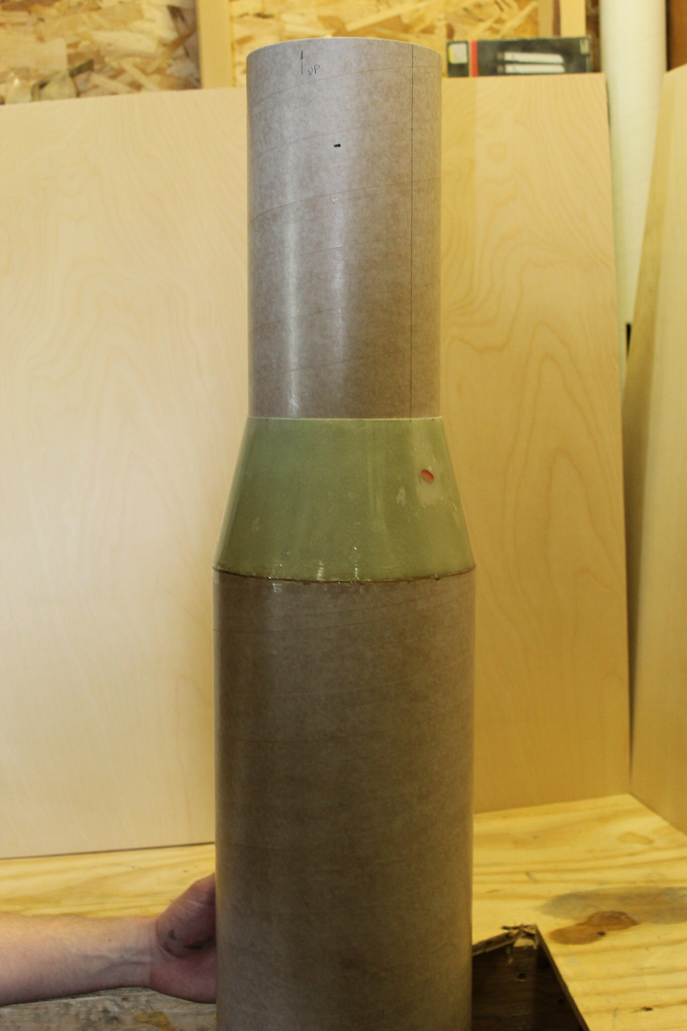
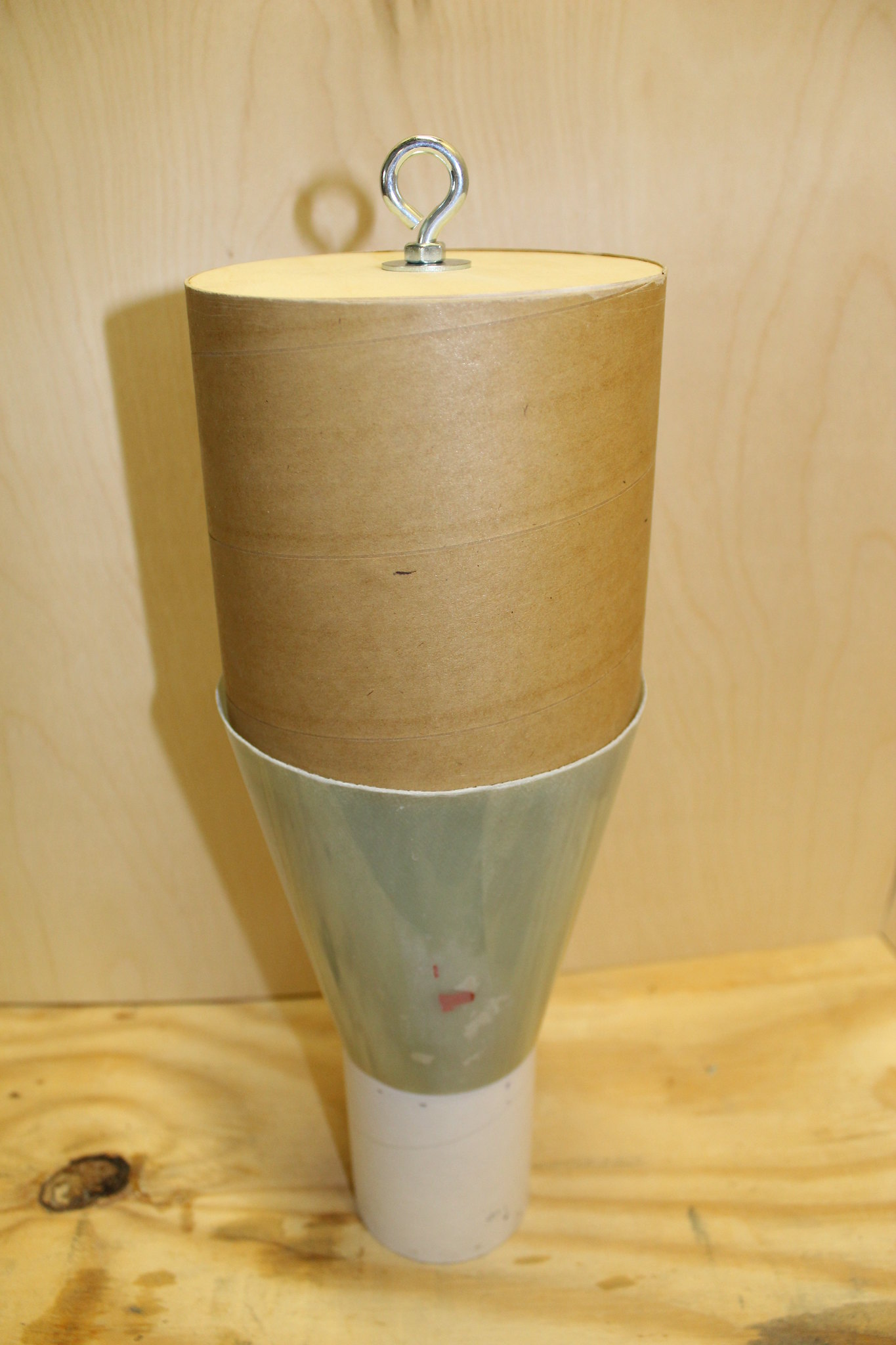
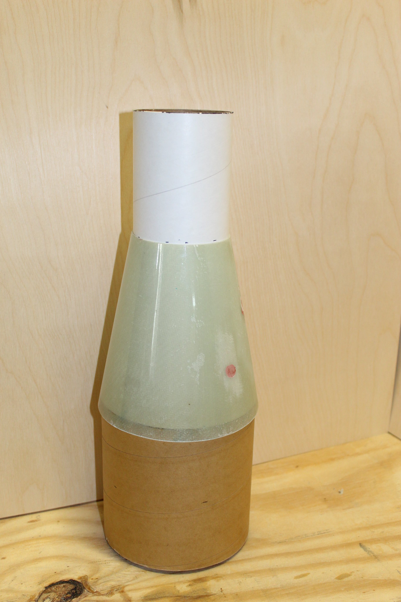
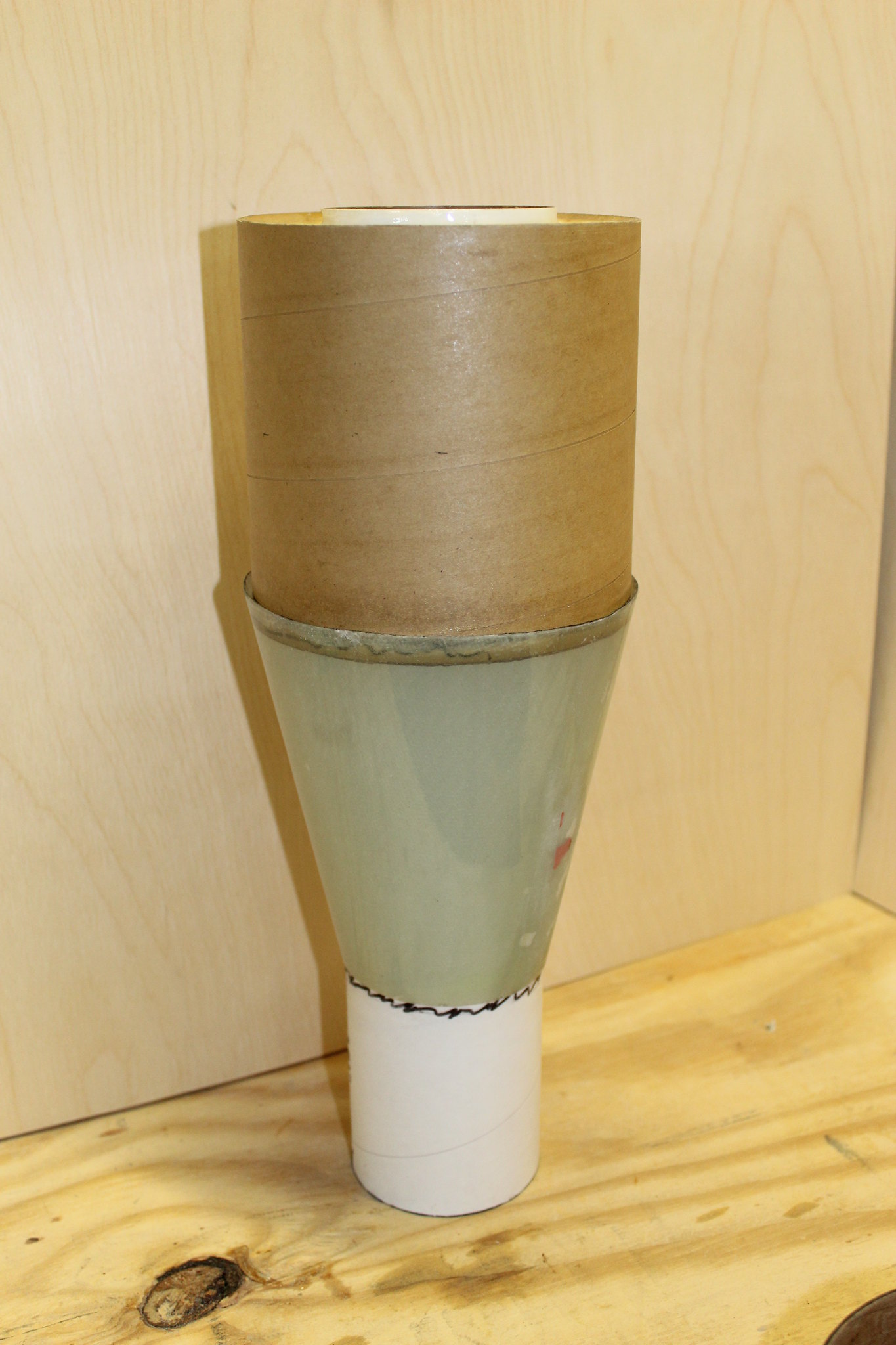
The model shown in the photos is the prototype...a quick built proof of concept project. The actual production model parts will vary slightly from shown (IE: you won't get the ugly duckling transition shown in the next few photos ;) Let's start the build with the top half!

Upper 7.67” Airframe Assembly

Summary of this Section: the booster section consists of a 30" length of 7.675" OD airframe. This section, essentially a complex nose cone, sits atop the booster section.


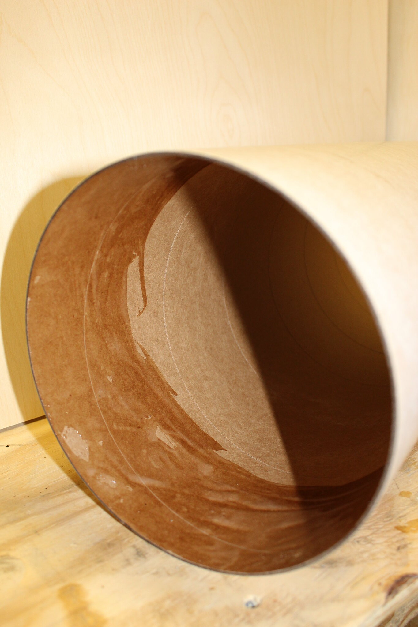
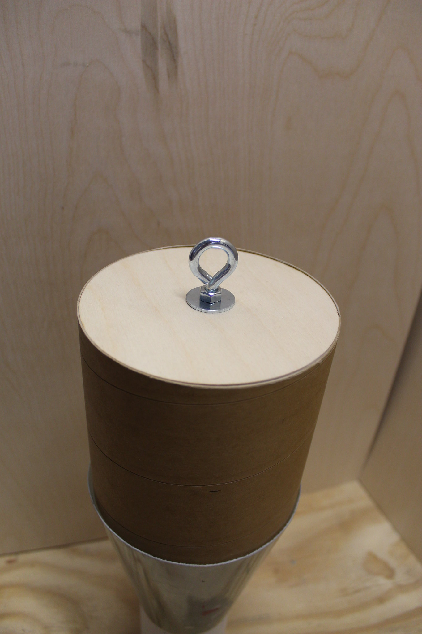
Begin by installing a U-Bolt, and then epoxying a bulk plate into one end of the 7.5” coupler. Epoxy the Stiffy coupler inside the coupler as well. Fillet both sides of the bulk plate.

*Note*: if the builder chooses to build their Saturn V with electronics based dual deployment, they may choose to build this coupler as an Electronics bay.
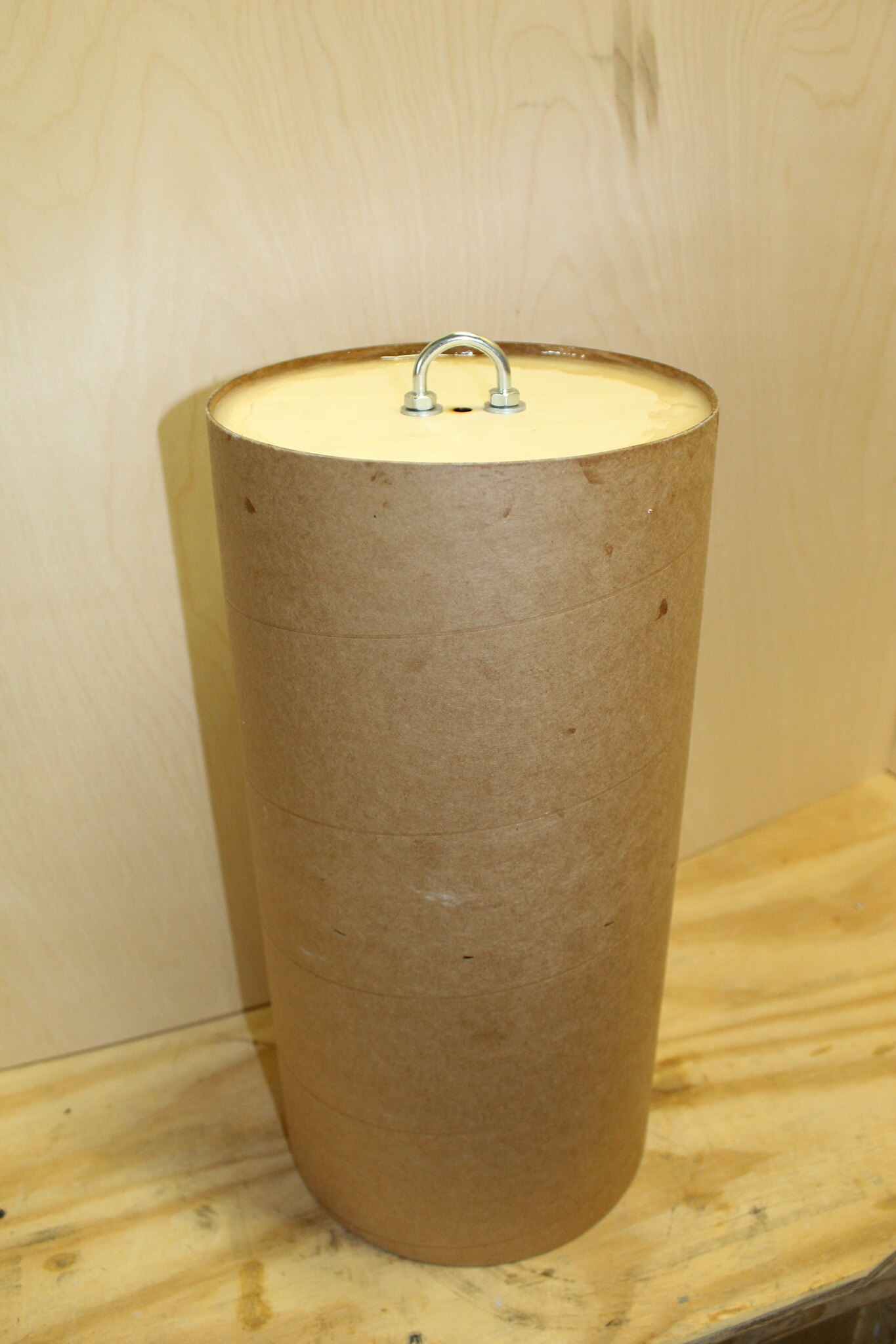


Make marks around the perimeter of the 5.54” tube 9.92” from one end of the tube (10” is fine, just be consistent!). This is where the top of the lower transition will sit.
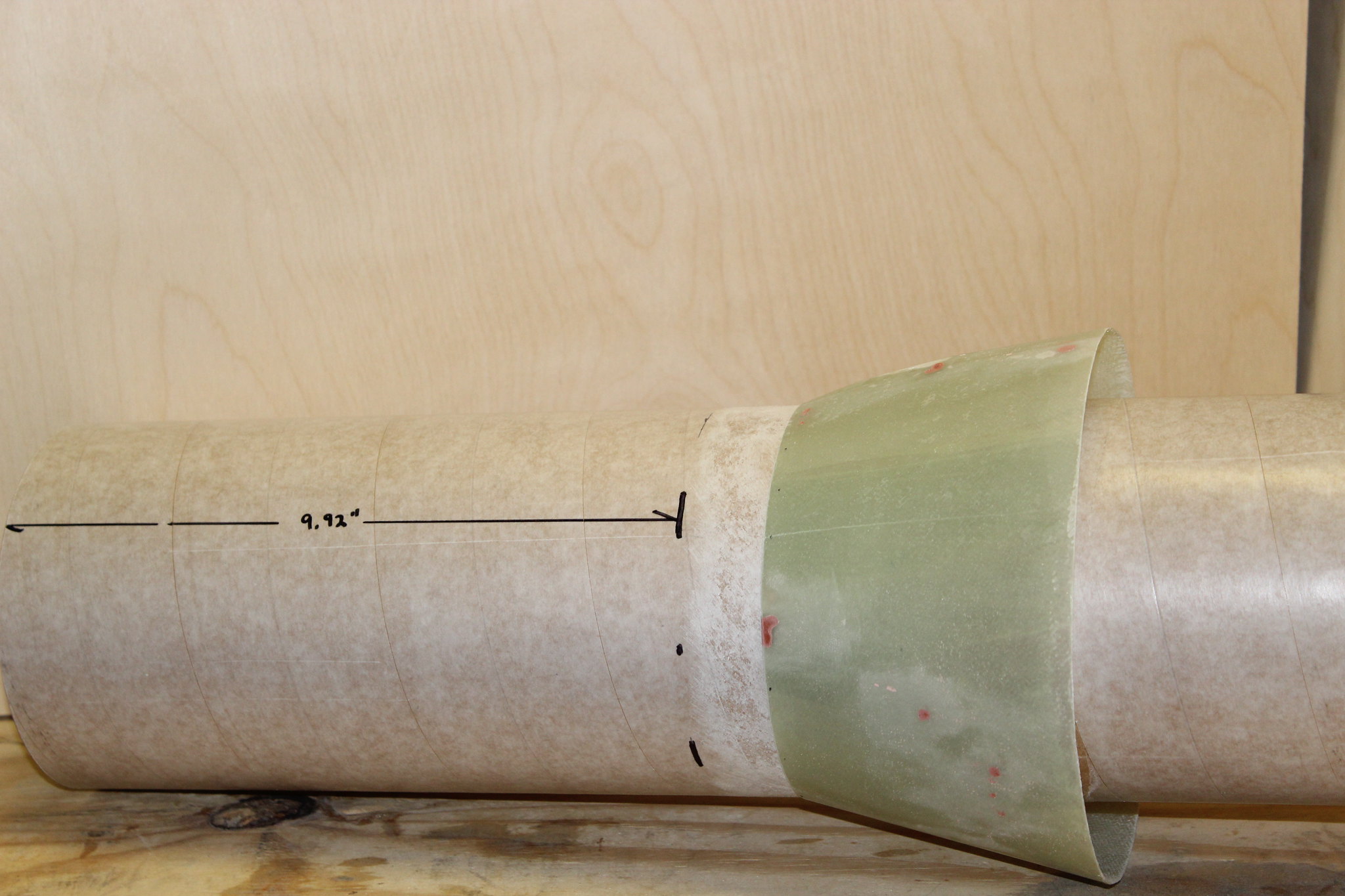


Slide the lower transition onto the 5.54” tube. Two 5.54” to 7.5” centering rings will be glued to the 5.54” tube below the transition as shown. Square up the lower transition using the top centering ring, 7.67” airframe, etc. Mark the airframe and scuff the tube as necessary.
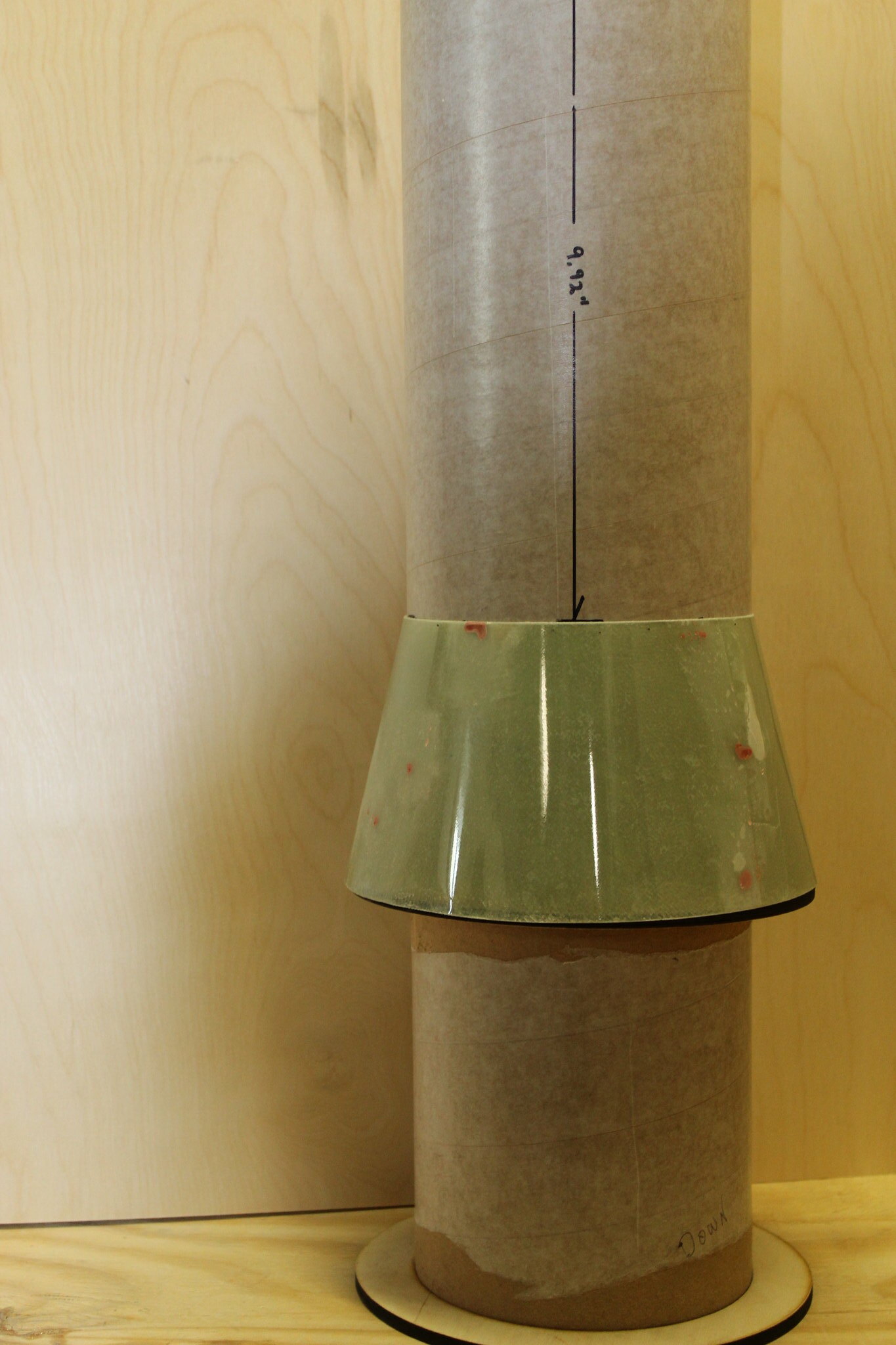


Prepare to epoxy top ring and transition in place
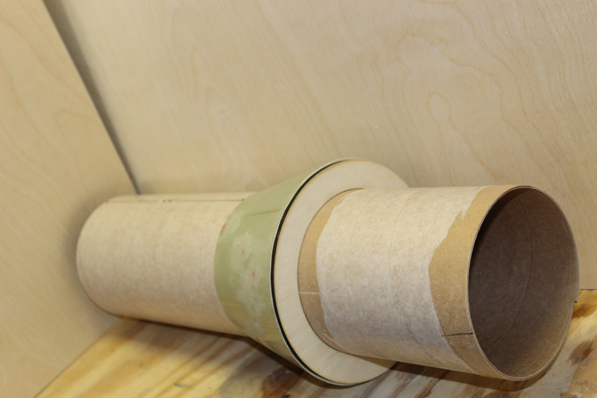

Epoxy it all together! The builder may choose to use a slower setting epoxy in order to allow time to ensure proper alignment of the transition. No pressure, but don't screw it up!:D Apply epoxy to the following areas:

-base of the transition where it meets the top edge of the centering ring

-top of the transition where it meets the 5.54” airframe

-Fore and aft edges of the top centering ring where it meets the 5.54” airframe

-Fore and aft edges of the bottom centering ring where it meets the 5.54” airframe

Clean up any excess epoxy, ensure proper alignment (use 7.67” tube if necessary), set aside to dry.

Epoxy lower centering ring 1/4" up from the end of the 5.54" tube. Fillet the ring-to-5.54" tube joints, set aside to dry, and admire your good work.
 
Last edited:
(7.67" to 5.54" upper airframe continued)

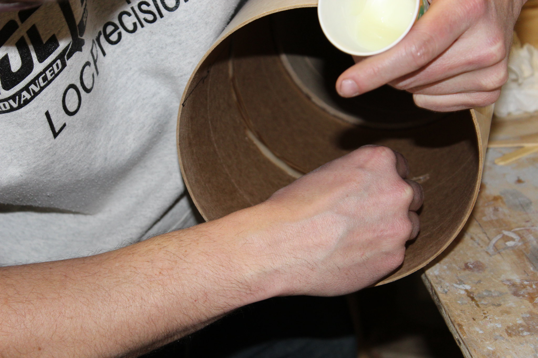
Mix up a batch of epoxy and smear it around the inside of one end of the shorter 7.67” tube.


Install the previously completed coupler/bulkplate assembly.

*Note: standard practice is to epoxy it in halfway (7.5”). However, be mindful of motor length and recovery space with the relatively short booster section (30”). The builder may choose to install the coupler further into the upper 7.67” airframe to allow more room for longer motors and recovery space.*


Make a ring of epoxy 5” in from the open end of the shorter 7.67” tube. Don’t stop; proceed to the next step immediately!


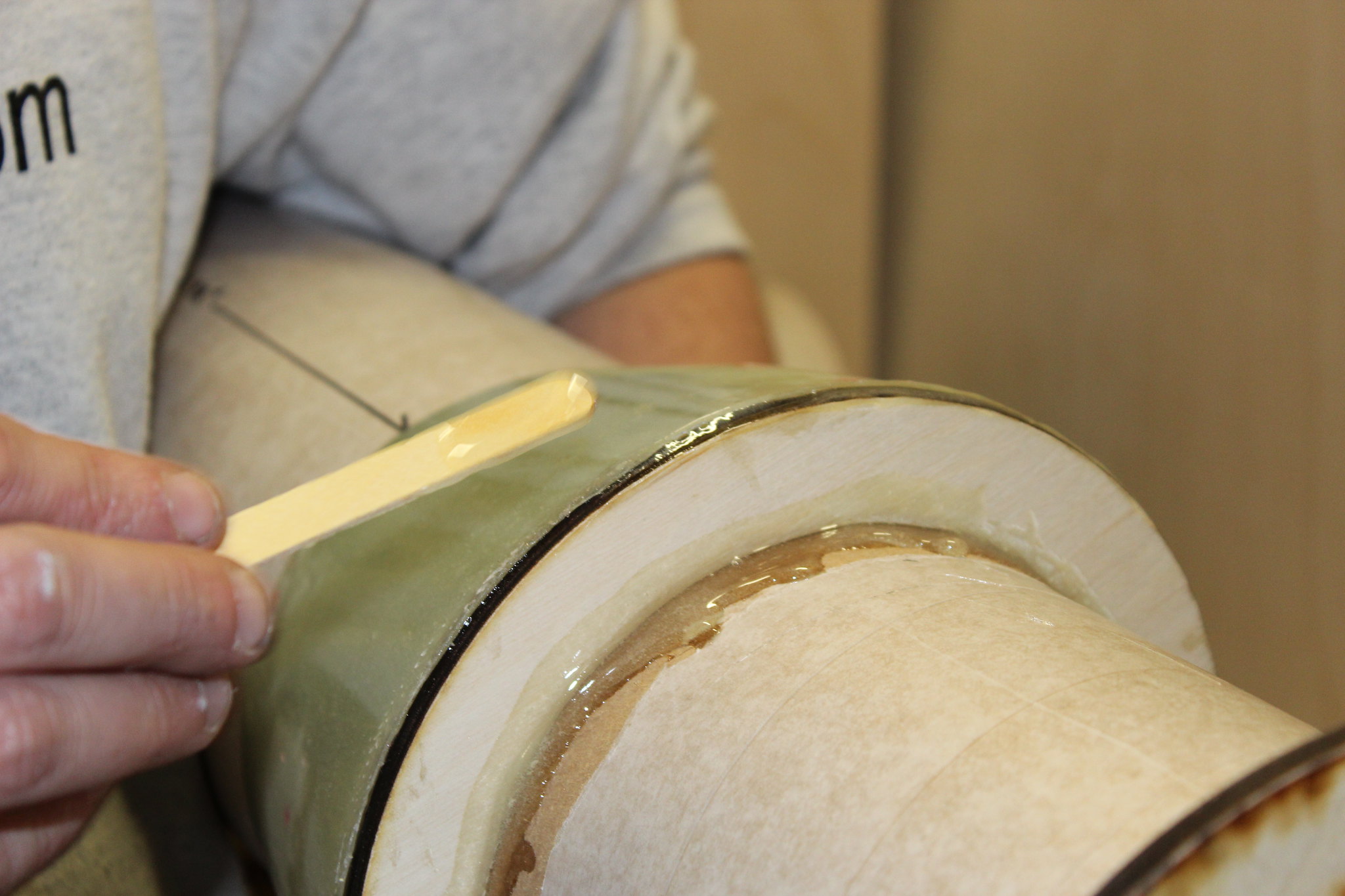
Apply epoxy around the perimeter at the base of the transition.


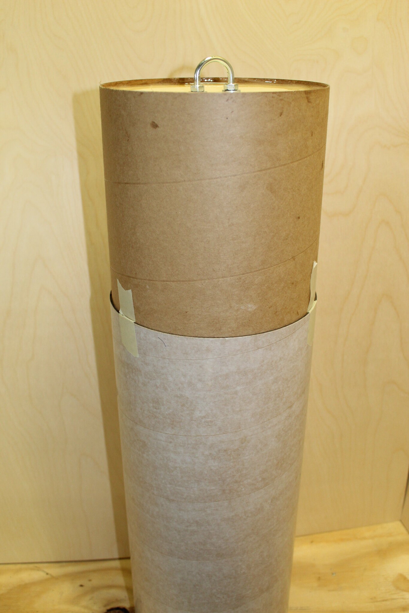
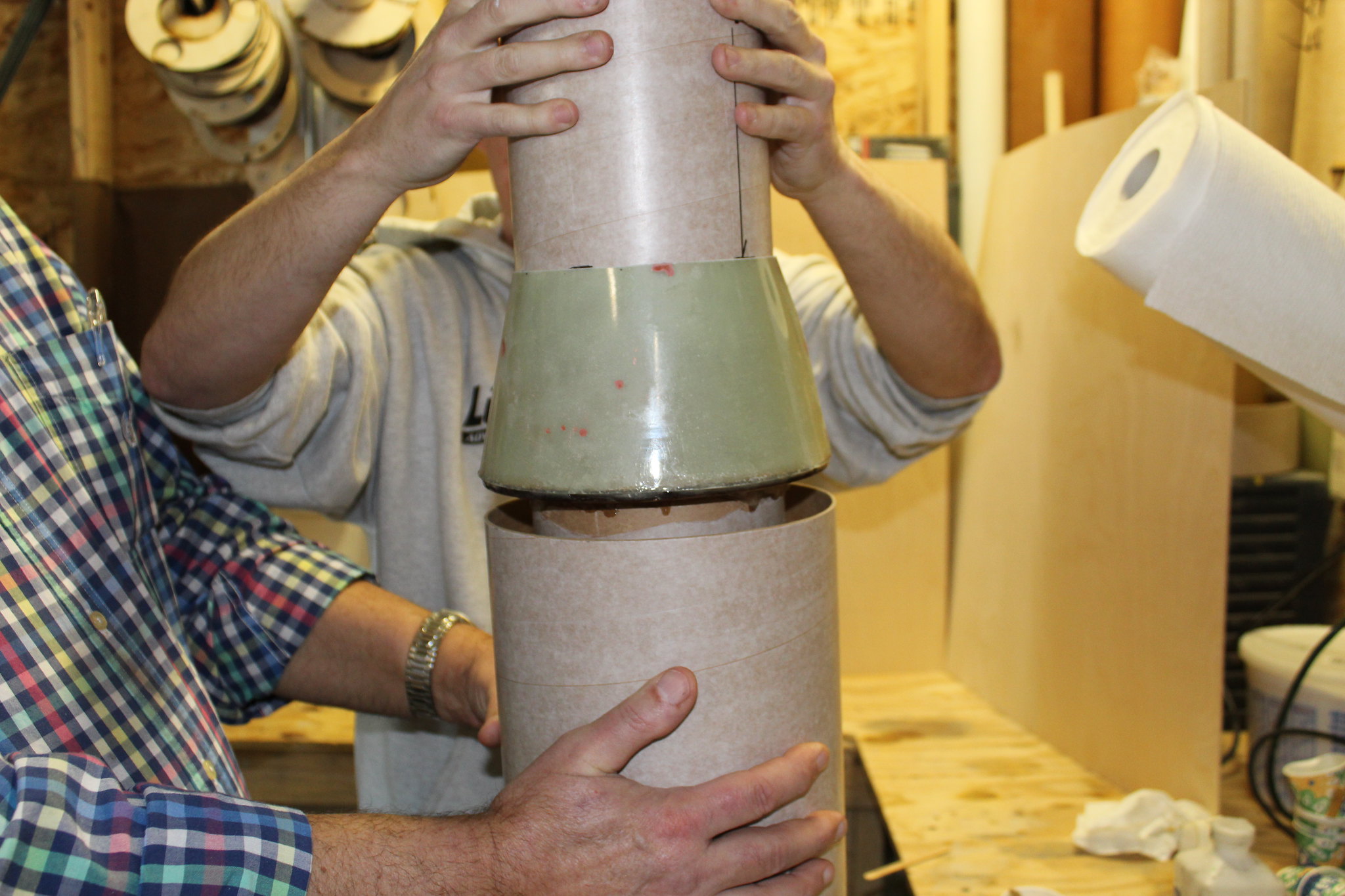
Slide the 5.54” airframe assembly into the open end of the shorter 7.67” tube…the one where you just made a ring of epoxy on the inside!


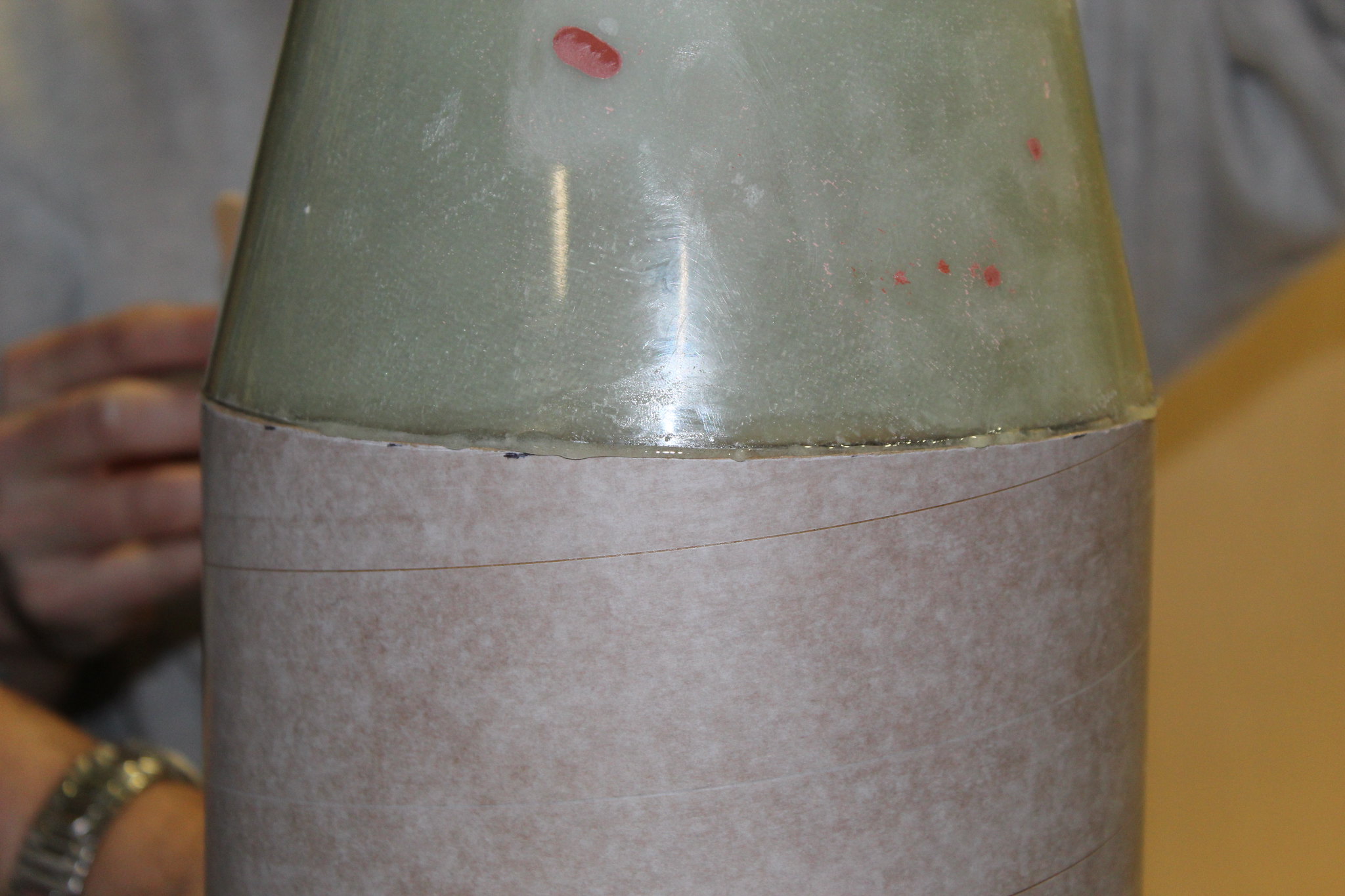
Slide it in completely; until the base of the transitions sits firmly on top of the 7.67” tube. Some epoxy should flow out of the joint at the base of the transition.


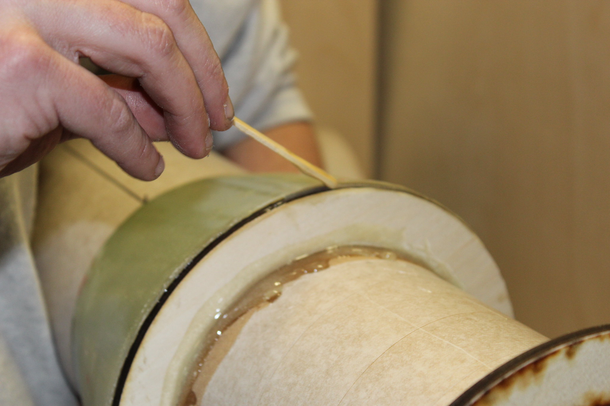
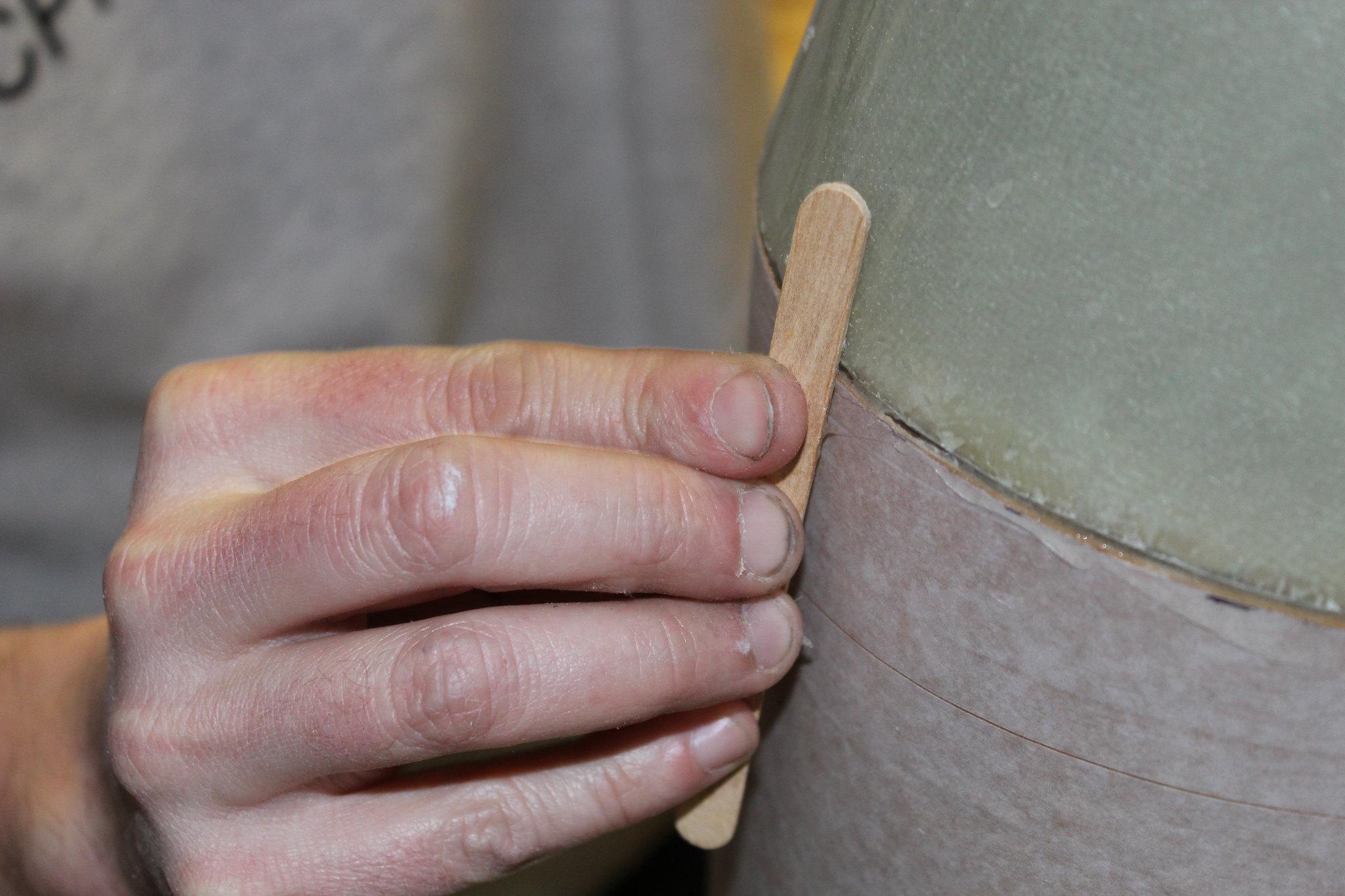
Wipe away excess epoxy using a stick (or similar). Follow up with a wipe of alcohol to clean areas of excess.


Verify the fit of the 7.67” to 5.54” assembly before epoxy cures. Once satisfied, set aside to dry before proceeding.

 
Upper 5.54” to 3.1” Airframe Assembly

Summary of this Section: This section transitions from the 5.54” to 3.1”; and is *either* a part of the nose cone (for single deploy), or a separate nose cone (for dual deploy). When in doubt, build it as a separate nose cone that can be affixed to the 5.54” tube using screws, or epoxy later on. If using as a nose cone, make sure you install a bulk plate with an eyebolt!

Important Note: the 3.1” tube is the PERFECT place to install noseweight. The prototype had a three pound cartridge that rode along in this tube. The cartridge was simply a 3” coupler filled with dense material. Make sure to secure any noseweight securely so it does not shift under the stresses of flight!

Dry fit to ensure proper fit.

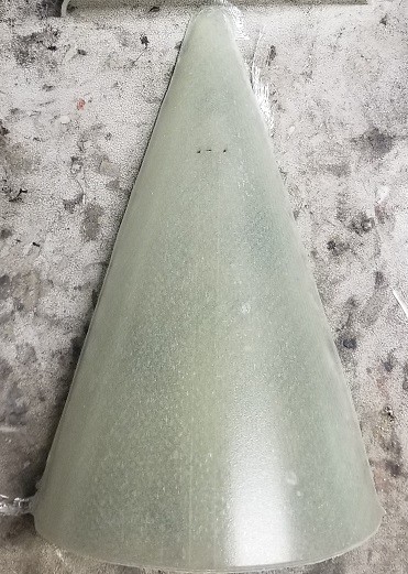
Note: the transitions will likely ship to the builder slightly undersized on the top ends for the tube they slide over. The reason is that this allows the builder to fit/fair the transitions as desired. (Cutting the tops of the transitions to fit over the tubes will leave a small ridge at the tops of the transitions). Hint: Use a Dremel tool with a sanding drum to carefully remove material from the inside of the top of the transition to blend with the airframe it slides over. If someone wants a photo of said process, please let me know and I’ll do so asap.


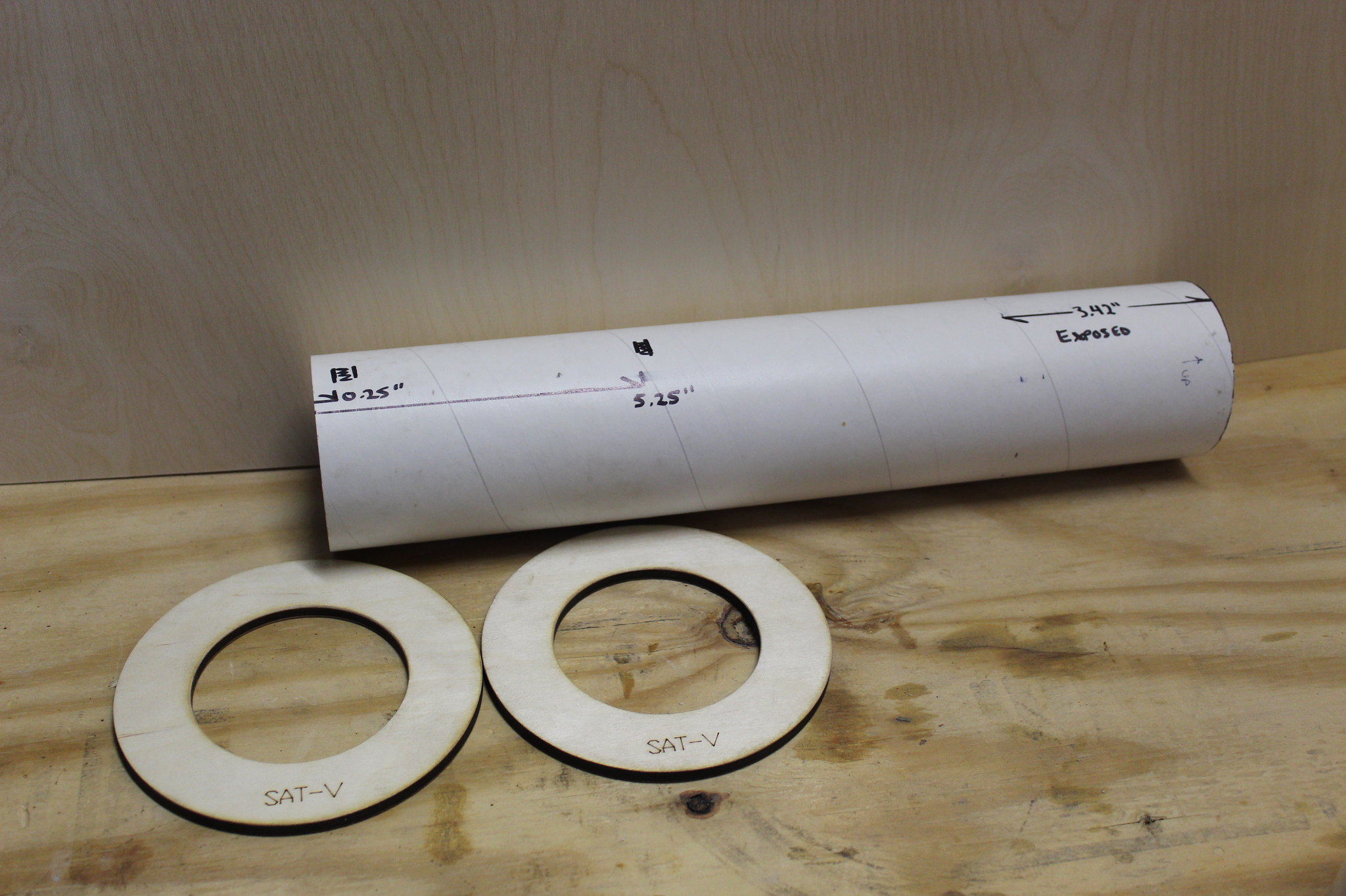
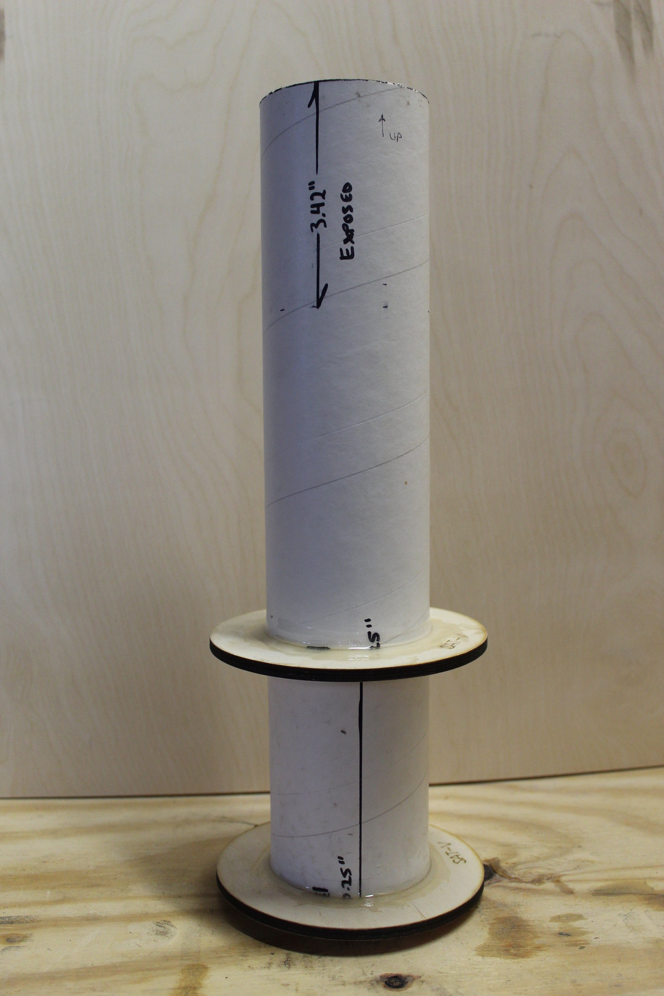
The two coupler centering rings (pictured below) should be epoxied roughly 0.25” and 5.25” from one end of the 3.1” tube. Verify fit and rough up surfaces before bonding.


Once fit is verified, epoxy two rings in place. Fillet both sides of the ring-to-3.1” tube joint.


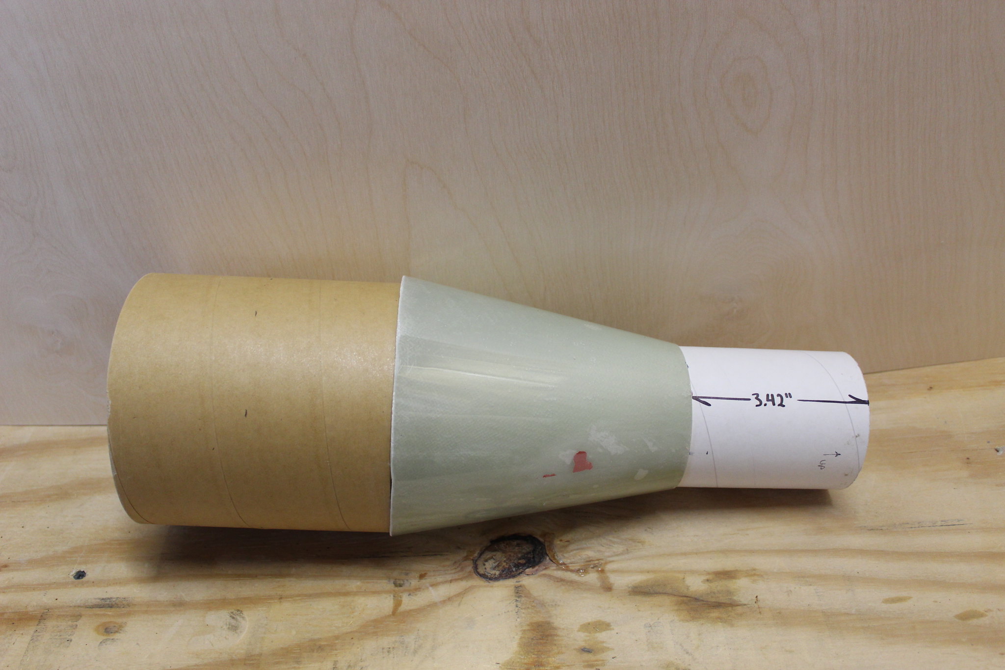
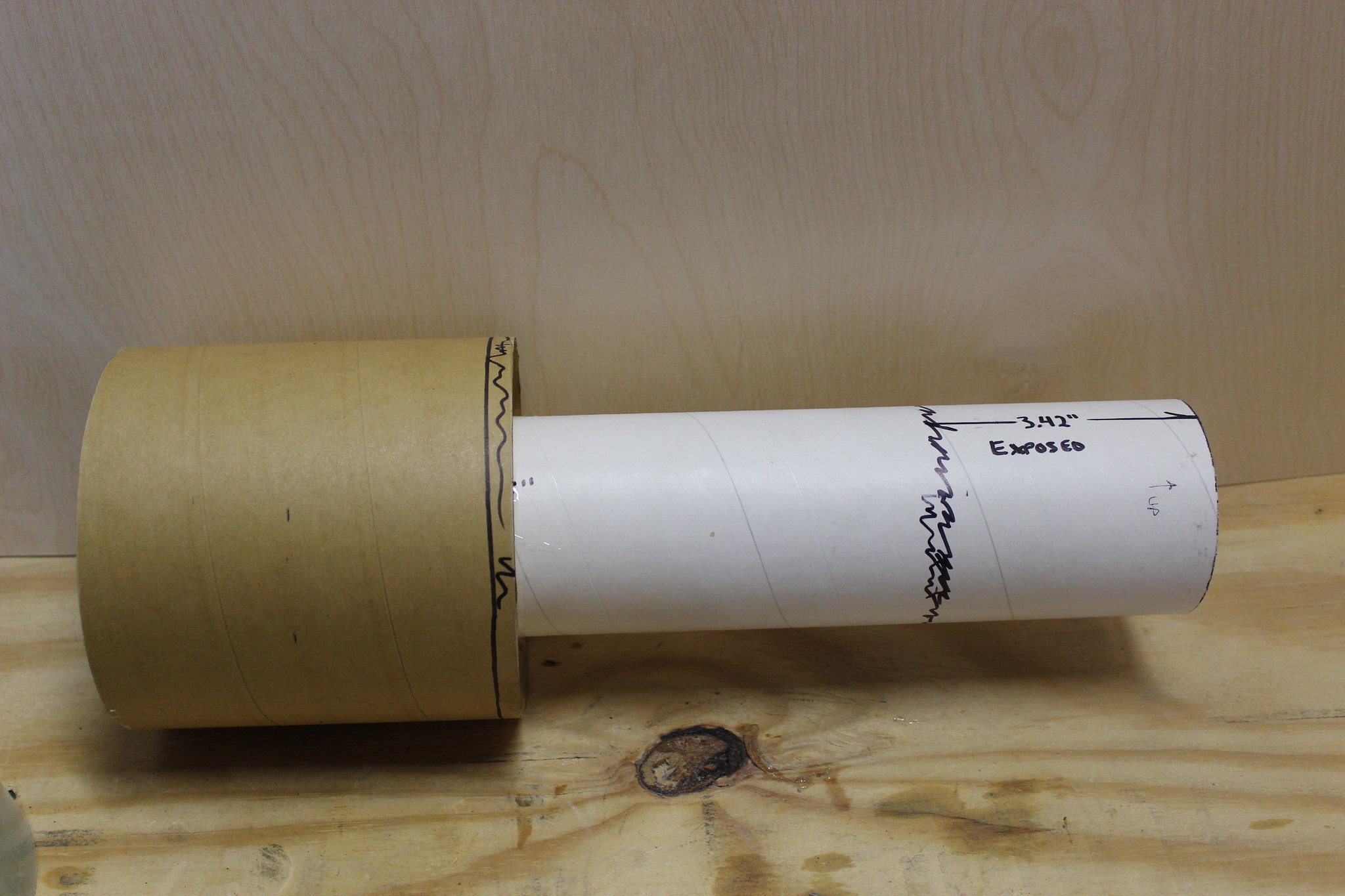
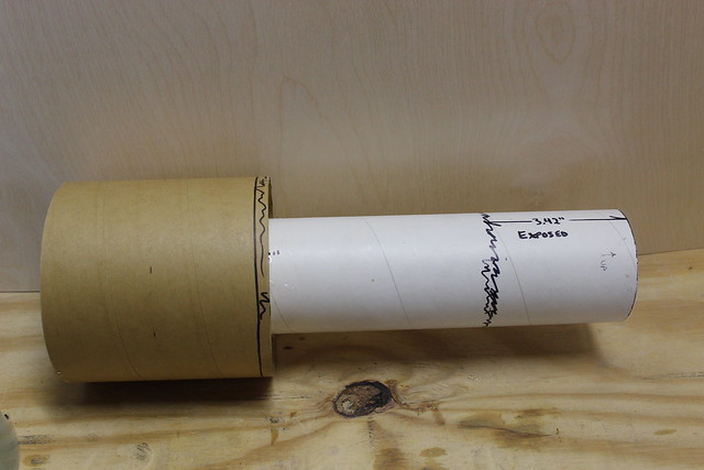
Epoxy 5.54” coupler to the rings. Use the upper transition to position the coupler properly; leaving 3.42” of 3.1” tube exposed on the top end.


*IF you intend to use this as a nosecone as described above, leave room for the bulk plate. The bulk plate may be epoxied in place, or fastened to the aft ring. I recommend the latter, to allow for removable and adjustable nose weight.


Fillet ring-to-coupler joints and allow to fully cure.

Verify transition fits OVER the 3.1” tube and OVER the edge of the 5.54” coupler.


Apply epoxy in the areas highlighted with black squiggly lines in the photo. In words: about 3.25” from the top end of the 3.1” tube, and around the top forward edge of the 5.54” coupler.


Slide transition over the top of the 3.1” tube, down onto the epoxy rings you just applied. Verify location…3.42” exposed at the top. Tape in place if need be; allow to dry nose down so the epoxy flows into the voids at the tube/transition joints. You can see the epoxy through the fiberglass; you do NOT have to fill the entire void between the transition and coupler with epoxy or otherwise.


Note: it is a good idea to test fit in the top of the 5.54” tube prior to epoxy curing as well! The transition should be "proud" of the coupler tube, with the bottom of the transition lining up with the outside diameter of the 7.675" airframe.


Last edited:
3.1” Tower Assembly

Summary of this Section: Let’s face it: no Saturn model looks right without the tower/capsule on top! What we came up with here is a compromise between functionality, survivability, and scale looks. The prototype survived landing nose down on a frozen lake bed unscathed! And we think it looks pretty good too!

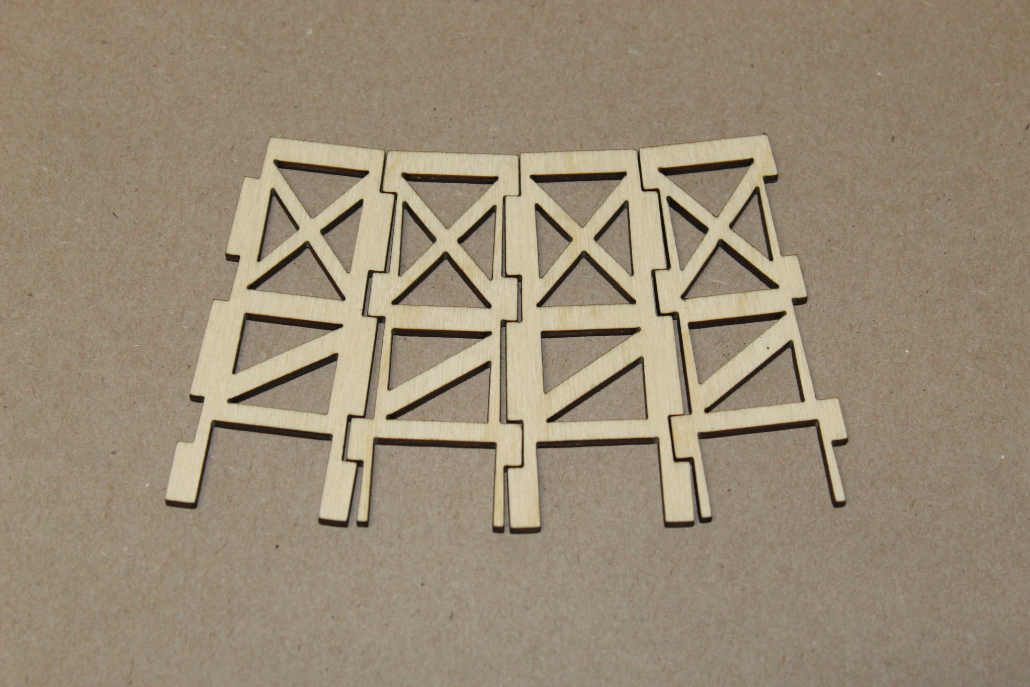
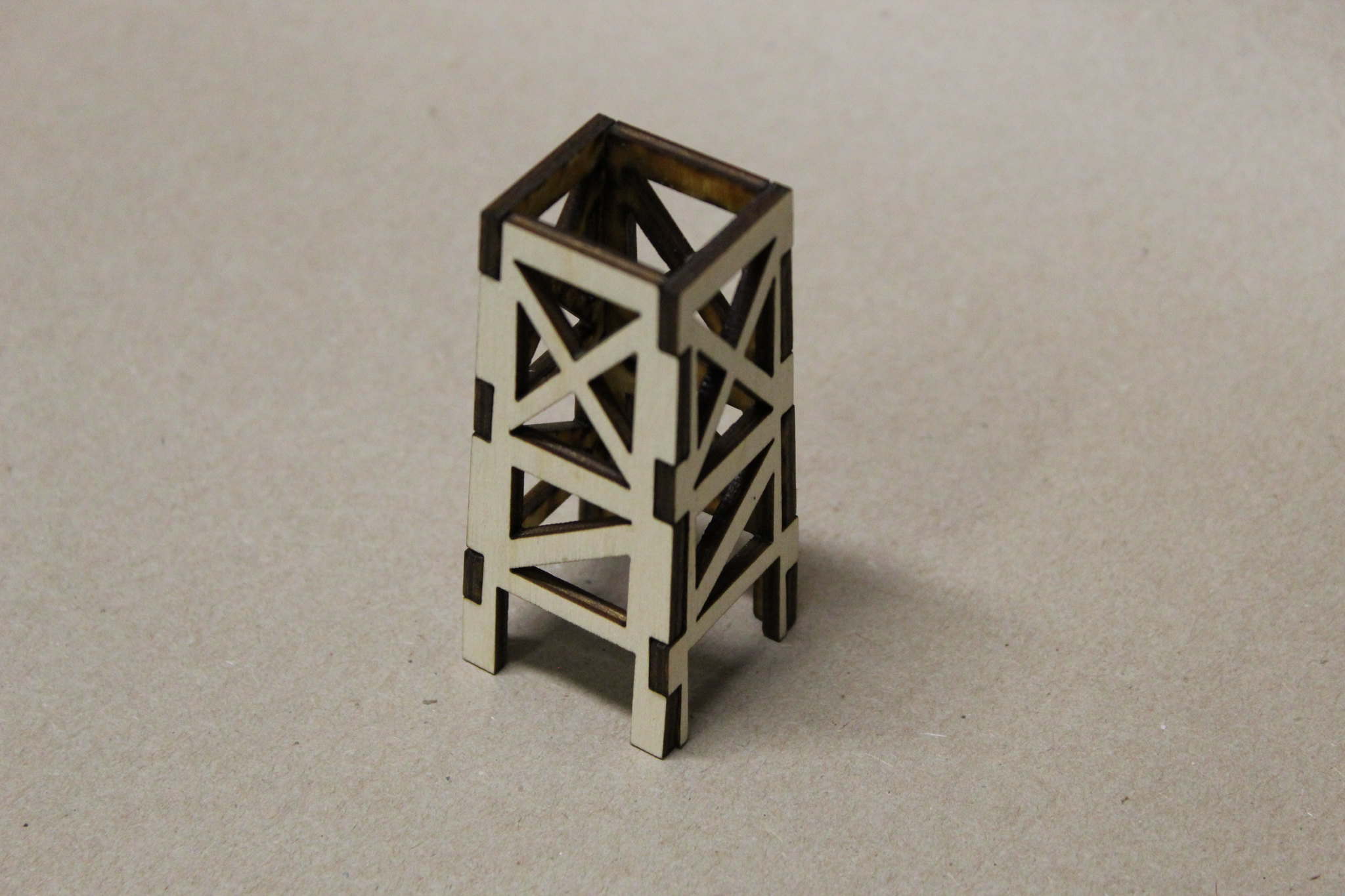
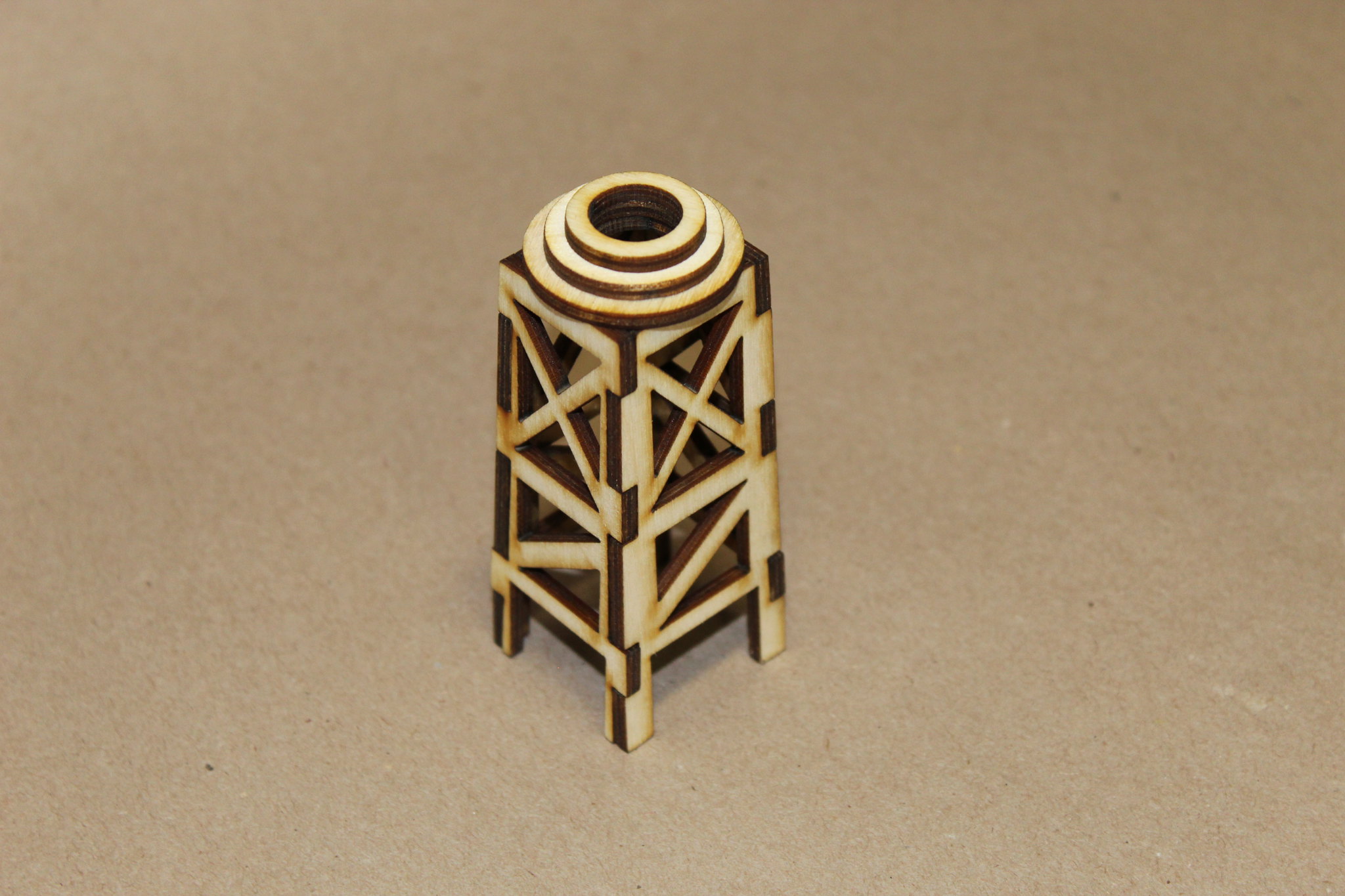
The tower is interlocking laser cut plywood.


Glue together using wood glue, CA, or even epoxy.


Glue the three small rings together. Make sure to keep them centered (or you’ll have to re-drill the ½” hole in the center after). Glue atop the tower.


Fill the voids in between the rings with your favorite putty, and sand smooth, if desired. I really like the smelly spot fillers for this; or use Elmer’s CWF, or Superfil; whatever floats your boat! No photos of this step.

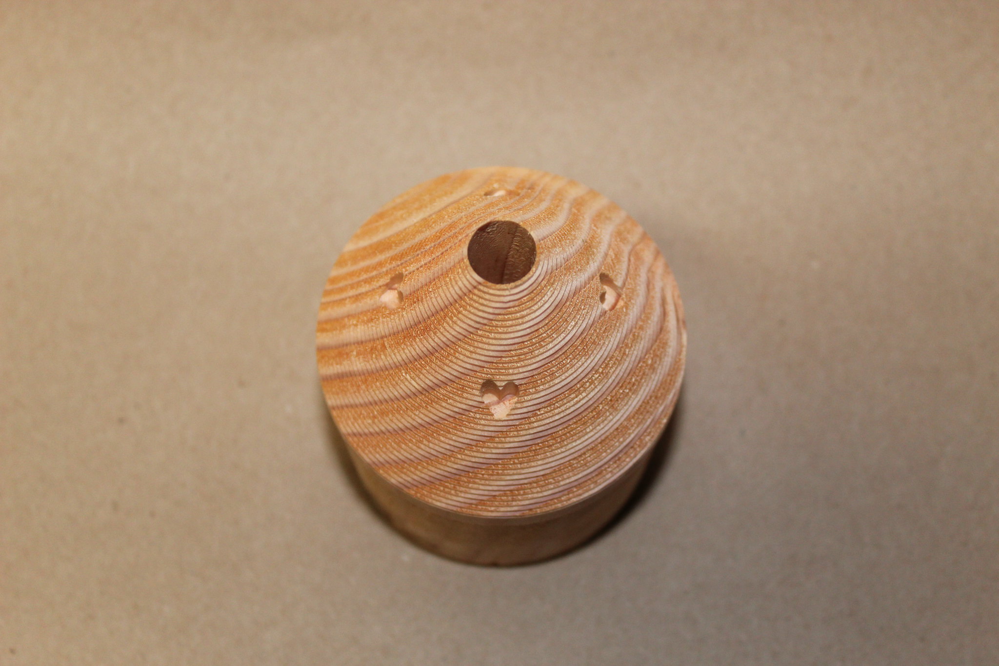
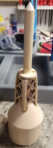
Fill and/or sand your capsule as desired. The machining process leaves ridges that may be filled in, sanded down, or your favorite combo of both. I chose to sand the prototype down. Pre-sanding photo:


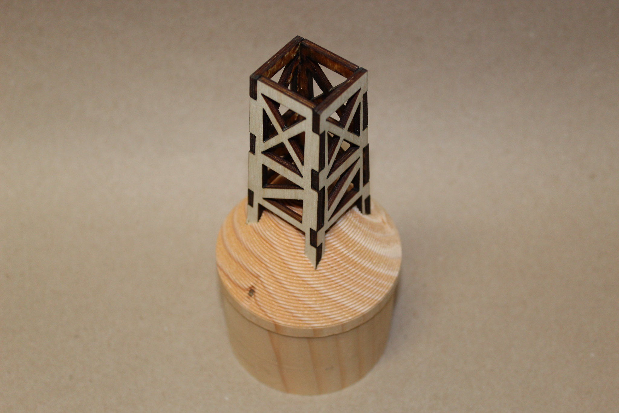
Marry the tower to the capsule using your favorite flavor of glue. Those pre-cut slots are the bomb!


Glue in the ½” dowel, leaving the proper amount exposed. I forget the exact amount…somebody remind me to come back and edit this with the correct length!

Finish as desired with filler, sanding, priming, and painting. Pre-paint, pre-production example (I was in a bit of a hurry; the production version is a lot nicer!):


When completed to your satisfaction, test fit, and epoxy into top of 3.1” airframe tube. With access to the inside of the 3.1” tube from the bottom end, I can’t think of a reason not to permanently epoxy the capsule assembly in place.

Congratulations, you just completed the functional top half of a monster Saturn V!
 
Last edited:
Oh man I can't wait. Mine might have to move to the front of the build list

The first dozen or so kits are boxed up and ready. More coming SOON! Heck yeah, get that Punisher finished and clear space for the Saturn! :)

This is cool. Looking forward to the rest.

Thanks John! Happy to have you here. The rest...coming at you shortly!

boy this is some project!

very nice work so far

Thanks Theory! It was, and is a fun project. Though after the first week in April, I'm taking a nap!;)


Thanks BK! Welcome aboard!

Looking good sir... I dig the kit. :)

Thanks Justin Griffin! I like turtles too!:D


Booster build coming asap....
 
7.675” Booster Build

Summary of this Section: We need somewhere to put those five motors! A 30” section of Loc 7.67” airframe is the base of this beast.

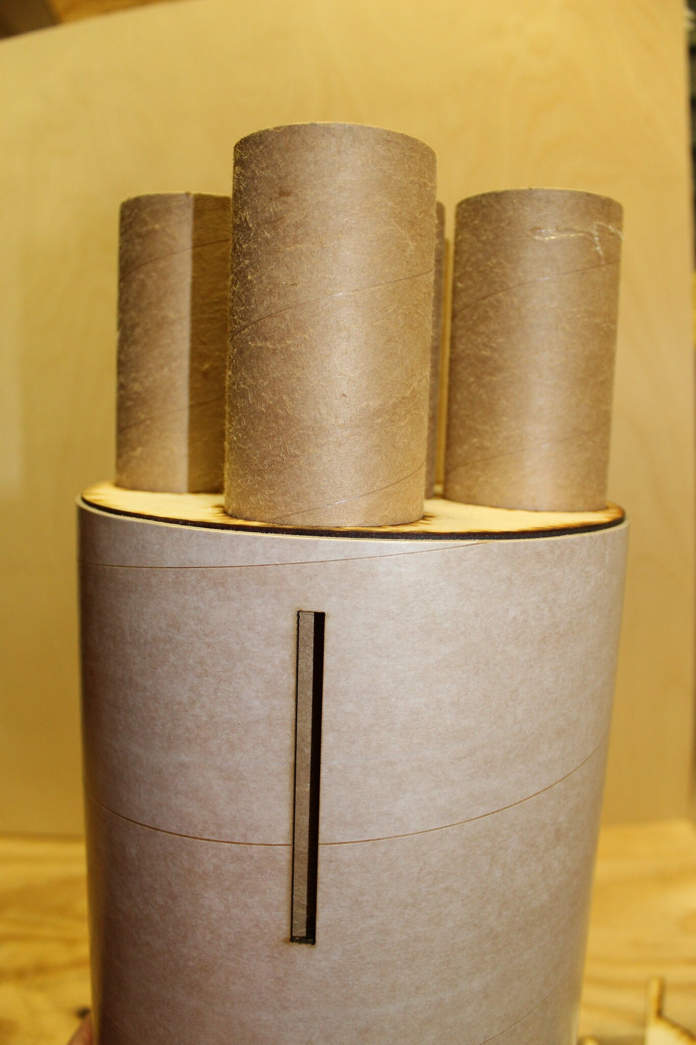
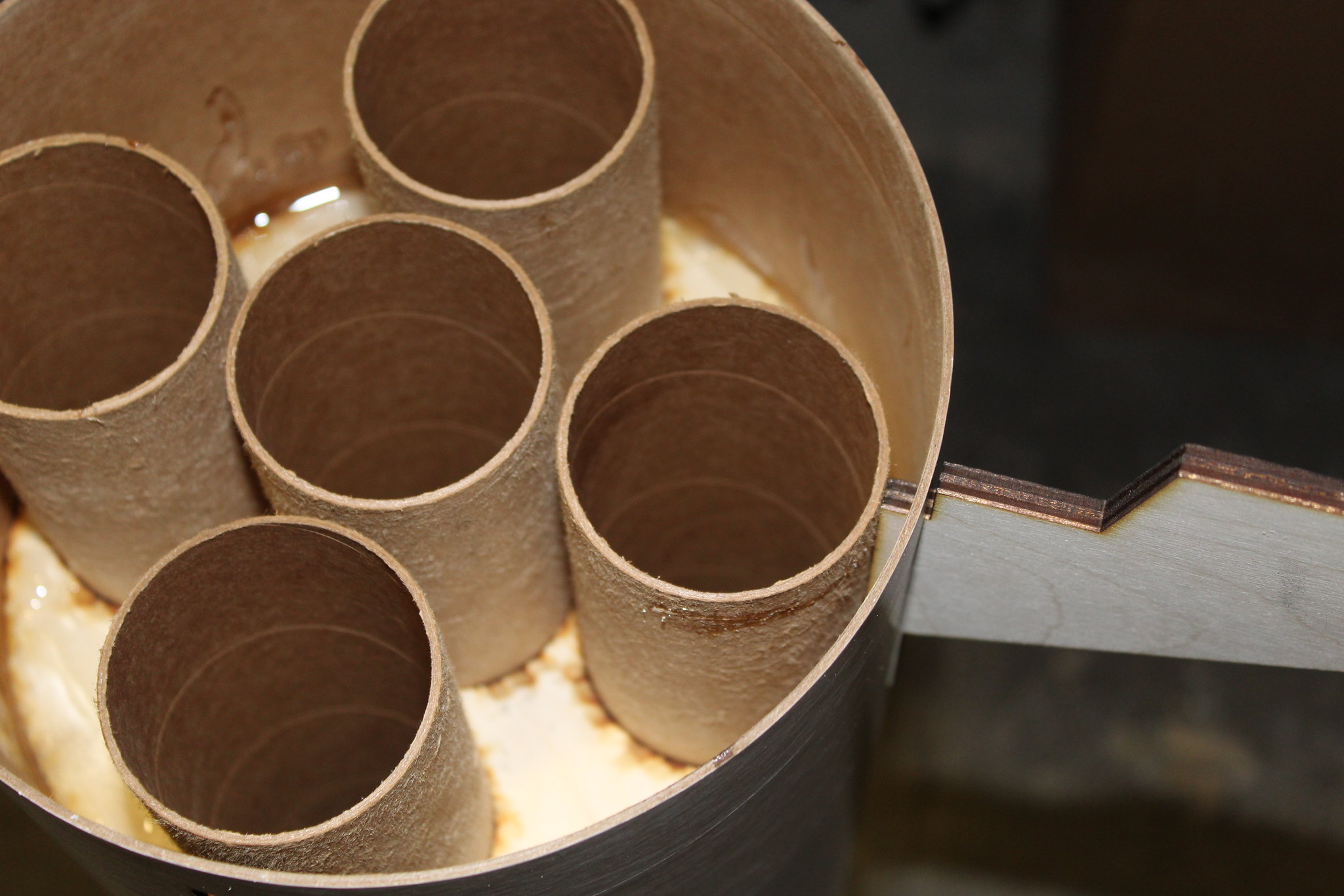
The motor mount consists of three centering rings and five motor tubes. The prototype utilized (5) 54mm tubes; the production version gives you the option of (5) 54’s, (1)75 and (4) 38’s, or (1) 98 and (4) 29’s. Assembly is the same regardless of your choice.

Begin by installing the two U-bolts on the forward centering ring. A nice Y harness is included which does a great job distributing the load on the forward ring and decreasing the chance of a zipper from a less-than-perfectly timed deployment “event” near apogee; I like it!

Dry fit the components together to make sure you have a good fit, and that you’re familiar with the layout. In this case, we peeled the motor tubes to better soak up the epoxy, and used the fins as spacers on the bottom side. The motor tubes rested against the work surface while the aft ring was propped up just a bit using mixing sticks.

*Note: no fancy motor retention intended or included on the proto…just drill, tap, and use machine screws and fender washers on the this one.


The upper two rings are epoxied in place and filleted. Do not epoxy the aft ring in place at this time!


Once cured, test fit the motor mount into the booster tube.

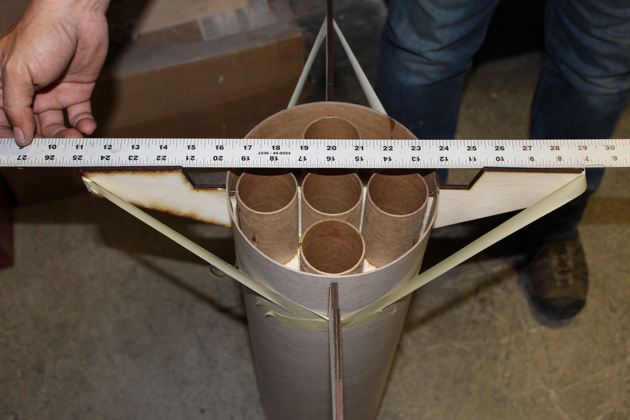
*Note: the outboard motor tubes must align with the fins! This is important to make scale sense!


Stick a fin in the slot(s) to make sure everything fits as it should.


When satisfied, epoxy motor mount into the booster tube. Again, verify alignment of the outboard motor tubes and fin slots; they should align!

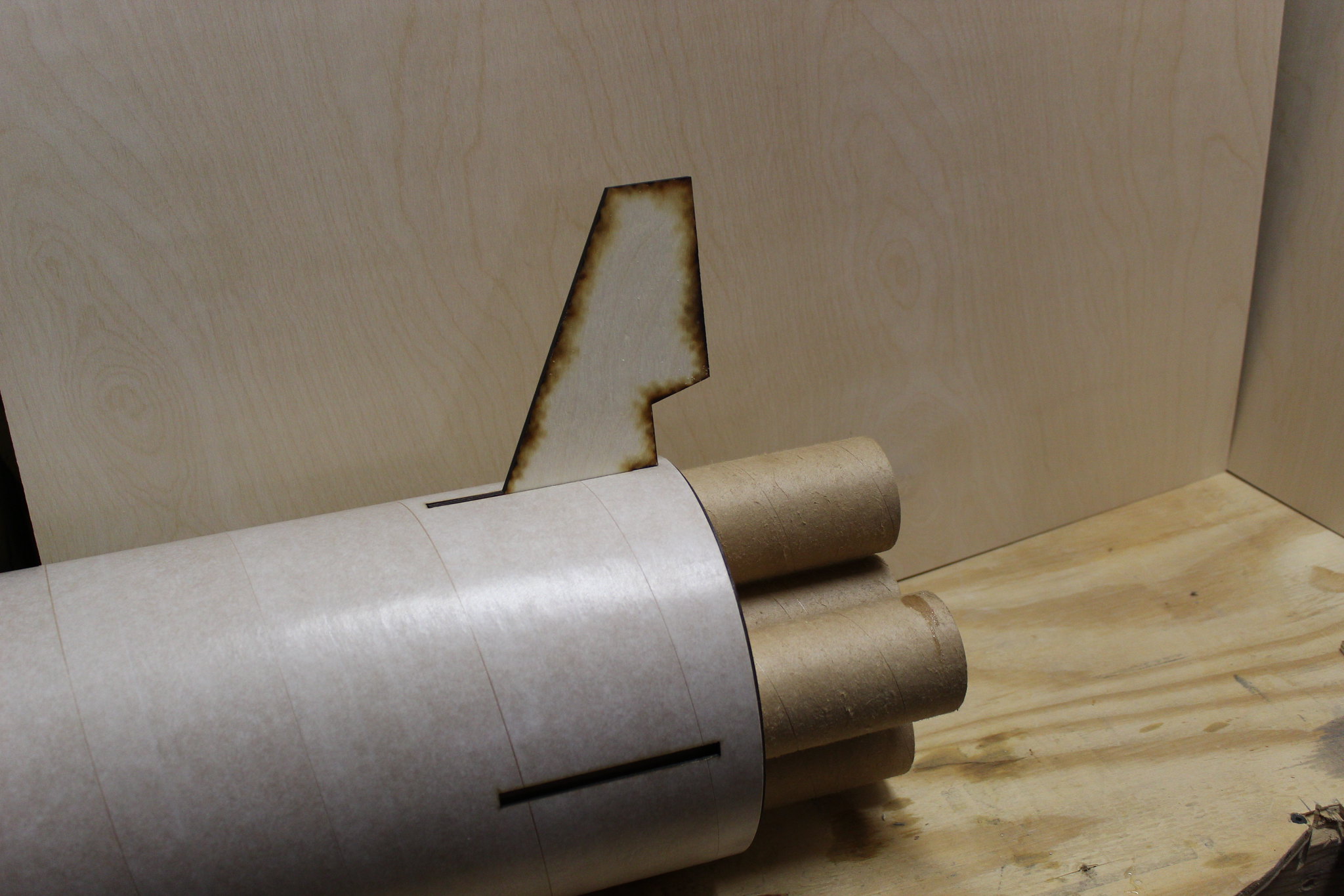
Once the motor mount is firmly epoxied to the booster tube, test fit the fins one last time. If they fit as desired, apply a healthy bead of epoxy to the root of the fin. Insert, align, secure as necessary (tape, jig, guides), and allow to cure. A “nose down” attitude for the booster works well for this step!


Fillet fins to your satisfaction. Nominal fillets will not affect the fin fairings that fit over the top.

The fin fairings on the prototype were plastic….the production run is fiberglass. More on the fiberglass parts in the next post. In the meantime, the fiberglass fairings have a slight indentation, ¼” wide, where the fin goes. It's there if you look close; rubbing a pencil over the ridge helps with visibility. This slot must be cut out by the builder. A Dremel tool with cutoff wheel is ideal.


*Note: the indentation is 4.5” long, along the surface of the fairing. The builder may choose to make the slot length shorter if desired. It works like this: the 4.5” indentation will have the base of the fairing beneath the bottom edge of the airframe AND beneath the trailing edge of the fin; essentially at the scale location. This location is probably best for the scale purists. A shorter slot, however will seat the fairings up higher on the airframe, which is less scale, but more durable on landings. The choice is up to the builder!

No photos of the install here (yet), but here they are installed on the proto, and stacking the pieces together.

Note: fillet the inside of the fairings; accessing them from the tail end of the rocket. Small external fillets may be used for "blending" if desired, but are structurally unnecessary.


Next post will be on the glass parts. A bit of the history and fine tuning of the parts to fit your model.
 
Not the first person I'd attribute that quote to :D

1*NEVWE956OQKIWbWhmPjWjQ.png
v
 
My openrocket sim shows 81.5" with the fairings/fins sticking down a bit from the body tube bottom and with no nozzles.
 
Last edited:
That’s a big Saturn. What motors are you planning on flying?
 
This is a really cool build. One thing I notice from the pictures is that you aren't wearing gloves while epoxying. You really should be, both for your long-term ability to use epoxy and to show your customers the right way to build the kit.
 
V2ORK.JPG I created a special openrocket/rocksim file for my version with single 54 mount, this includes all actual weights of parts in the right places, with some weights added for parachute, kevlar, altimeter(I use a small bay in the bottom half butted against the inside of the 7.5" tube and just use it for main ejection, I don't fly high enough to warrant dual deploy), and added some mass for paint/glue as an estimate.

Jason said they used around 3# of nose weight for their flight, since I don't have the extra four motor tubes in the rear, which saves just under a pound including epoxy fillets so my sim is showing only 8-12 ounces needed for the k1103 the heaviest motor I plan to fly with 1.1-1.3 calibers of stability.

Frank
 

Attachments

  • SaturnV.ork
    3.9 KB · Views: 65
  • SaturnV.rkt
    42.8 KB · Views: 46
Last edited:
How tall is this beast when built?
Assuming around 85-86" tall if its near scale
My openrocket sim shows 81.5" with the fairings/fins sticking down a bit from the body tube bottom and with no nozzles.

Yes Sirs!!! There's 75.5" of "meat" from the base of the fairings (no scale nozzles) to the top of the wood capsule. Add the tower on top of there for another 8 or so inches.

That’s a big Saturn. What motors are you planning on flying?

First flight was a single K550 to about 2500'. Future flight plans include a cluster of K185 or equivalents, and an L1000 core, airstarting two K185's after L1000 burnout, to another two K185's after the first pair burnout.:)

This is a really cool build. One thing I notice from the pictures is that you aren't wearing gloves while epoxying. You really should be, both for your long-term ability to use epoxy and to show your customers the right way to build the kit.

AGREED! Good call!

I will say that minimal epoxy was interfaced with skin during the rapid assembly of the prototype. But you are absolutely correct!

I will also say, that I promise that nitrile gloves were worn for each and every layup of the 185 epoxy-fiberglass production parts so far. Plus the 24 molds, plus the plugs,..... Only another 120 or so to go!o_O
 
here is a special openrocket file for my version with single 54 mount, this includes all actual weights of parts in the right places, with some weights added for parachute, kevlar, altimeter(I use a small bay in the bottom half butted against the inside of the 7.5" tube and just use it for main ejection, I don't fly high enough to warrant dual deploy), and added some mass for paint/glue as an estimate. I have not added nose weight yet, as I want to convert this to rocksim since I can use the less pessimistic CP calculation before I plan nose weight. I've hacked the CG location at this time just to get the sim to be stable, you can see some of the motors I plan to fly it on. There are a few weird things in the sim that had to be used to get things to adjust right, the 5.5" tube is broken into two parts, but total length is what's included in the kit, and the upper 7.5" section is actually a 15" section and a 3" section for a switch band.

Jason said they used around 3# of nose weight for their flight, since I don't have the extra four motor tubes in the rear, which saves just under a pound including epoxy fillets, I may be closer to 2#

Frank

View attachment 377851

Looks great Frank!

Note on the CG: the first flight had the CG exactly where you have it marked on the OR file. Agree that it could probably go aft a bit. But I'm conservative....a scaredy cat!

Also, what is the length of 3.1" tubing you have up top? Is that 15"? It looks short to me?
 
The total length is 14" exactly what I got in my kit with about 3.75" exposed above the transition. Note my kit had a 24" section of 5.5" tube as well, Jason said you could cut that sorter as you only had around 10" exposed and 10" in the transition/centering rings...


Looks great Frank!

Note on the CG: the first flight had the CG exactly where you have it marked on the OR file. Agree that it could probably go aft a bit. But I'm conservative....a scaredy cat!

Also, what is the length of 3.1" tubing you have up top? Is that 15"? It looks short to me?
 
SVRocksim.PNG View attachment 377858 View attachment 377859 Here is what rocksim shows for CP, using rocksim stability as opposed to borrowman it moves the CP from approx 52 to 59" aft of the tip, almost a full caliber. Given that and accounting for more than one caliber of stability it is showing only 8-12 ounces nose weight needed.
I'll add some more altitude sims. This works for any of my motors from J570/J415 up to K1103X
 
Last edited:
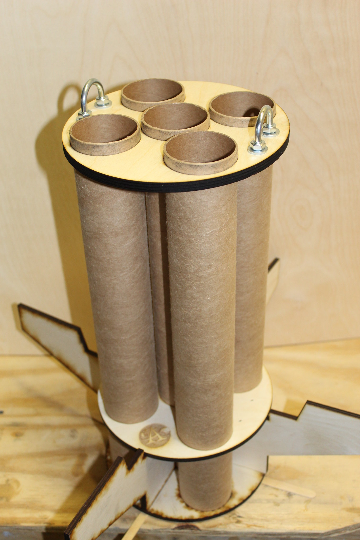
I also ordered four of these to use as engine bells, I've used them on my Titan II missiles, they are stainless and pretty sturdy and aren't expensive and aren't very heavy, they may be a bit small, but they have the lines going around and are easy to simply screw to the bottom thrust ring. Since I'm running a single motor, I can mount these where the outboard motors will go and it will look approx right.

https://www.winedevices.com/product...g0ZjzvctJsq6QgTC7Abe8nIQtsbdyNtxoC4Y0QAvD_BwE

8144-2_530x.jpg
 
Last edited:
AGREED! Good call!

I will say that minimal epoxy was interfaced with skin during the rapid assembly of the prototype. But you are absolutely correct!

I will also say, that I promise that nitrile gloves were worn for each and every layup of the 185 epoxy-fiberglass production parts so far. Plus the 24 molds, plus the plugs,..... Only another 120 or so to go!o_O

I 100% agree that experienced applicators can keep epoxy off their hands (for the most part). It's the new people who have more trouble unless they have experience using epoxy and/or frosting cakes.
 
Hello Eric,

Just found this thread and if I was the kind of person who would say OMG, then I'd be saying right now. I'm not, but you get the idea I'm sure.

Now for a couple of questions.

1) Kit? Kit by whom? Are you a part of LOC now, did I miss that somewhere along the line?

2) How much for a kit?

3) Seriously what will it take to get ahold of one of these beauties?

Brad the "Rocket Rev.," a very long-time LOC kit and LOC parts builder, Wilson

Yup. It's a LOC kit. A bit over $600. You can probably still order one. HIGHLY recommended! (I'll start building mine in a few days!)
 
Hello Eric,

Just found this thread and if I was the kind of person who would say OMG, then I'd be saying right now. I'm not, but you get the idea I'm sure.

Now for a couple of questions.

1) Kit? Kit by whom? Are you a part of LOC now, did I miss that somewhere along the line?

2) How much for a kit?

3) Seriously what will it take to get ahold of one of these beauties?

Brad the "Rocket Rev.," a very long-time LOC kit and LOC parts builder, Wilson
Here is a link to the kit:
https://locprecision.com/product/loc-custom-saturn-v/
 
Back
Top