Little Joe II A-003 Mission Build

The Rocketry Forum

Help Support The Rocketry Forum:

This site may earn a commission from merchant affiliate links, including eBay, Amazon, and others.

srfrich

Well-Known Member
TRF Supporter
Joined
Apr 20, 2019
Messages
82
Reaction score
35
https://www.rocketryforum.com/threa...-tips-tricks-and-modifications.131767/page-10
That, ladies and gentlemen, is one awesome thread. Many thanks to all the contributors.

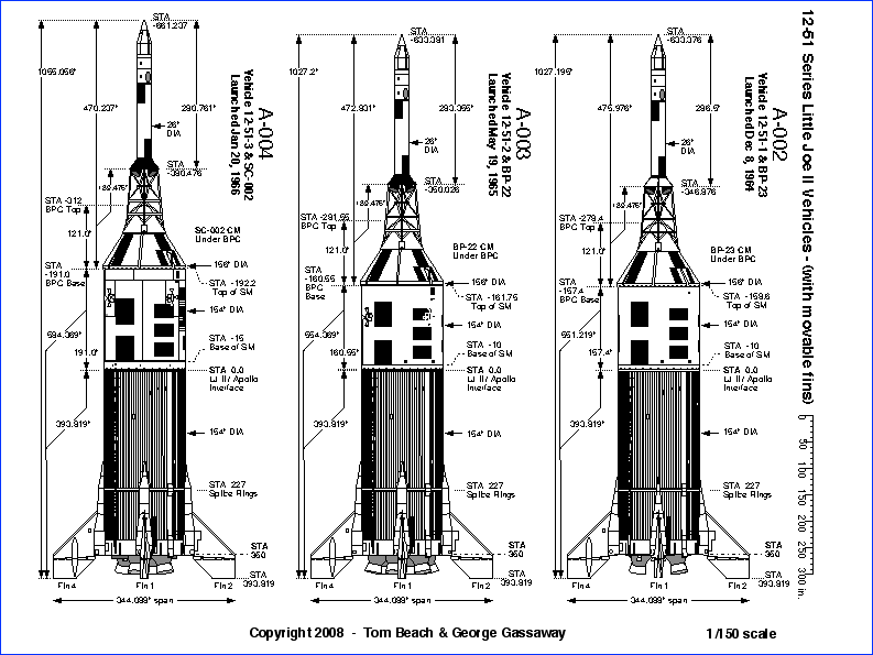
This thread is to record the adventures and misadventures of modeling a specific LJII Mission, A-003. The A-003 was the only mission flown with 6 Algol motors, 3 launch and 3 air-start. The intended altitude was 100,000', by far the highest of all the Apollo LJ missions, but it broke up at 12,000' due to a guidance malfunction.

Video: Little Joe A-003 mission

This build is to model a successful A-003 mission using the Estes 1/45 scale kit, using a 6 motor cluster of D10s, 3 launch and 3 air-start.

The build has the following parameters:
  1. Have a ton of fun
  2. minimize build time. (i.e. emphasize function over aesthetics, while paying all due respect to the mission.)
  3. enjoy using Open Rocket software for design and prediction
  4. fly successfully with a 3/3 air-start configuration of six D10 motors
  5. build the motor mount so each motor thrusts through the CG
  6. reinforce the Launch Escape System tower to hold more nose weight for stability
  7. model the Apollo capsule descent beneath 3 large parachutes
Optional Parameters:
  1. model jettisoning of the LES tower with safe recovery
I read that the Estes kit is sized for the A-004 mission, and the A-003 mission was a tad shorter. So, I will probably cut the tubes down a bit, and reduce the wraps/decals accordingly.

The air-start avionics are planned to be the Transolve TripleFire with a ground transmitter. Heck, I would love to fly this thing, not only launch it! TripleFire would also give me the option to manually trigger the LES tower jettison if so desired.

Here is my initial Open Rocket design. There is plenty of nose weight in the LES tower. With 6 D10's loaded the CG at launch is a bit behind the capsule shoulder, giving a stability of 1.22 cal. Launch weight of 1.68 lb. This will be flown as a Large Model Rocket. Predicted altitude is about 400m.

LJII 3D view RF 4-20-19.jpg
 
Last edited:
Here is a plot of the Center of Gravity (green line) during a simulated flight. The CG starts at 32.55 cm at launch, and moves to 31.55 cm at booster burnout. Then the CG moves again to 30.45 cm at sustainer motor burnout. Taking an "average", the booster motors would thrust through at CG at 32 cm, and the sustainers through a CG at 31 cm. Won't know if the difference is significant enough to mount the boosters and sustainers at different angles, but I have the idea to use a laser bore sight in the motor tube(s) to hit a 'target' positioned inside the airframe tube at the theoretical CG(s). The upper centering ring would need to have elongated holes so the upper ends of the motor tubes can be adjusted radially. Then freeze each motor tube into alignment with CA. The motor mount may be the last part of the assembly, because actual CG won't be known until then. OR CG plot.jpg
 
Last edited:
12-51-series-150.gif
According to Tom Beach & George Gassaway data, the CSM section of the A-003 mission was about 31" shorter than the A-004. At 1/45 scale, that equates to about 11/16" or 17.5mm to cut off the main airframe tube for the A-003.
 
This will be flown as a Large Model Rocket.
There's no such thing as a Large Model Rocket after the revision of FAR 101. This is a Class 1 rocket requiring no notification of the FAA, waiver, etc, as 6xD10 only has 60g of propellant total.

I think you'll find that getting all of these motors ignited the way you want will be pretty challenging.
 
There's no such thing as a Large Model Rocket after the revision of FAR 101. This is a Class 1 rocket requiring no notification of the FAA, waiver, etc, as 6xD10 only has 60g of propellant total.

"Large Model Rocket" - that really dated me, didn't it? My last incarnation as a BAR was in the late 1990's. (Currently on my second reincarnation.)Thanks, and I just read the current FAR 101 subpart C.

I think you'll find that getting all of these motors ignited the way you want will be pretty challenging.

Yes! That's part of the reason to do it:cool:.
 
Received the motor mounts from UncleMikesRocketShack today. The 6 outer centering rings holes in the Estes kit are for the Algol plastic nozzles, about 20mm wide, too wide for an 18mm motor mount. Will have to overcome that later.
IMG_2430.JPG
Now it's time to stop talkin' and start 'cutting metal'.
Using hobby shop 1/2" OD styrene tubing, check out the fit with the LES tower nosecone:
IMG_2433.JPG
Drilling out the LES skirt was easy. There is a tiny depression in the center from the molding process which was easily found with the tip of my awl.
Drilled a pilot hole, followed that with an 31/64" bit, 'cause I was gunshy about how much of the shoulder would be left if I drill with a full 1/2" bit. I followed up with a 1/2" bit and hardly got any plastic; I think the last 1/128" on each side of the hole just got pushed away from the bit instead of being cut. So the plastic tubing didn't go through. To do it over again, I would've skipped the 31/64" bit and gone straight to the 1/2" bit. To get the tube to fit, I started with sanding the tube (mistake); then sanded inside the hole with a roll of sandpaper (no progress); then got aggressive with a round metal file and that did the trick. The plastic LES skirt is much tougher than I expected. Not much plastic left on the shoulder, but it is still substantial enough to hold the paper tube and I cannot pinch it closed. Now the tube slides, tightly, inside the LES skirt. I think you can see where I'm going with this...
IMG_2434.JPG IMG_2438.JPG IMG_2439.JPG IMG_2440.JPG IMG_2440.JPG
 
Last edited:
FF1B0E8B-6D6A-44E8-8D00-78B879043362.jpeg LES tower assembly - dry fit the struts between the capsule and LES skirt, then wick in some Tamiya Extra Thin cement on strut joints only. I still want to remove the skirt and capsule, just using them as jigs for the struts at this point in time.
 
Quick and easy fin assembly using Plastruct Plastic Weld and some clothes pins. Trimmed off about 1mm of the alignment post on the fin tip to ensure a good mating at those corners.
[for gluing technique, see post #280 on LJII Tips, Tricks, and Mods thread.]
IMG_2445.JPG IMG_2443.JPG
 
Last edited:
Staring to think in advance about build parameter #7, modeling the capsule descent beneath 3 large parachutes. In the picture, the parachute bloom is 5x the diameter of the capsule heat shield. At 1:45 scale, that equates to roughly an 18" bloom with a 24" parachute. It turns out that the Estes kit comes with a 24" red and white plastic parachute. I can order 2 more of these from Discount Rocketry.
IMG_2442.JPG
The distance between the capsule and the edge of the parachute would be roughly 40" at 1:45 scale; so, add 20" of kevlar shock cord between the capsule and each parachute.
 
Nose weight blues.
The problem every rocket builder understands: get the nose weight as far forward as possible. Build parameter #6 is solved by a structural styrene tube core from the nose of the LES to the capsule nose. The fit of the parts I have so far is just too elegant to abandon. However, 6oz of diving locker shot has too much volume to fit in the LES tube core. Reducing the amount of shot to within the physical limits imposed by the current design, the stability margin is reduced to .99 calibers, which is unacceptable.
Damon Shot.jpg
 
Last edited:
Last edited:
I have found out the hard way, that if the CG is UNDER the "N" in UNITED STATES, it may not be stable (some went unstable, others did not). if it is AT the N or higher, it will be stable (Never had one go unstable if at the N or higher). This presumes the "N" is located in the right place on the model. I never got around to specifying that actual dimensional location on a drawing. Rocksim hides whimpering in a corner trying to "sim" stability of complex things like this. Also, short but wide STUBBY rockets tend to wreak havoc with the "one caliber of stability" guideline, lots of short stubby models plenty stable with less than 1.0 caliber.

BTW - what diameter is "diving locker shot"??? THere's bound to be a lot of wasted air space in between, you could look at using some fine heavy powder or dense sand to pour in and tap-tap-tap onto a tabletop as you add the other shot, to help fill in the spaces. And keep tapping as you go, without dislodging the earlier shot/powder upwards.

The biggest benefit you'd get for your model in maximizing noseweight for the CG is that the clustering is likely to cause some pitch/yaw disturbance at liftoff, that could lead to instability, that a single engine model would not have occur.

One thing I'd suggest is to skew (slightly twist) the cluster engine mount rings, so the thrust will cause some roll. And hey, you'd be emulating the real A-003, to a point (just not to the point of ripping apart from centrifugal force).

Also, for the inward canting of the outer engines, I'd suggest round holes for both sets of rings. BUT make the hole spacing for the upper ring closer inwards, which will accurately angle the engine mounts the same. So you won't have to screw with laser sighting or other stuff like that.

LittleJoe-FAI-1-39.5.gif
 
Last edited:
2.6mm is between 6 shot and 7 1/2 shot. 9 shot is pretty common at 2.3mm and should be available where reloading supplies are sold. Lead powder is available if you want to do what George said, but I don't know how much you'd have to purchase. It might be easier to whittle a solid weight into the shape you need. You can easily saw it to shape and fine tune the fit with a knife. You can easily melt small amounts into a mold too.
 
Short fat rockets get some benefit from base drag,
MaxQ: Thanks for those Apogee newsletters.
Base Drag LJII.jpg
if [CG] is AT the N or higher, it will be stable (Never had one go unstable if at the N or higher)
George: The "N" will be the guiding criterion for stability.
the thrust will cause some roll. And hey, you'd be emulating the real A-003
GREAT IDEA ABOUT ROLLING THE SHIP!!! Either your idea of twisting the motor mount, or canted elevons.
clustering is likely to cause some pitch/yaw disturbance at liftoff, that could lead to instability
Especially if one of the boosters failed to ignite. For that reason alone, it would be better to thrust the motors through the CG. Question is, can the motors be skewed for roll AND thrust nearly through the CG? For that reason, I may use elevons in combination with a very mild skew for the motors. But I don't yet know the math behind it. PS - I remember briefly meeting you at NARAM 18. Those were the days.
Lead powder is available
tbzep: yes!

Moving the CG forward by two modes: denser material (lead), and maximizing packing density of spheres. Lead shot is surprisingly hard to come by in California; the "diving locker shot" I have is small but not lead, it is probably steel. Lead shot is significantly more dense than steel shot, and it is available in California not from reloading supply, but from lab supply in #6 and #9 shot, $40 w/shipping for 500g. Which to buy? Will #9 shot pack more densely than #6 shot? Mathematical theorists say that the packing density of equal sized spheres is constant regardless of sphere diameter, i.e. #6 shot has bigger air spaces between pellets, but #9 shot has more air spaces, so it equals out. BUT, there is the surface effect of the container, and smaller spheres would pack more densely against the inside of a small cylinder, i.e. the LES tower core. Now, enter Lead Powder. The packing density constant for spheres goes out the window when using unequal size spheres (or packed powder which is like tiny spheres). Powder will fill the voids between all sizes of shot. So unless I learn anything new in the next few days, it will be Lead Powder + some plain ol' lead split shot from the fishing store. Will be interesting to see if that gives me enough advantage to save the LES/capsule design.
 
I didn't notice you were in California. You could probably walk along a highway and find enough old lead wheel weights to ballast a battleship. Trim them to shape and slip them in the tube with no voids whatsoever if you are a good whittler. You should also be able to purchase solid diving weights, new and used, that you could cut and trim to a near perfect fit. A 2 lb uncoated lead weight is $5.69 at Dolphin Scuba in Sacramento.
 
You should have enough sand to fill the spaces between the pebbles between the gravel.

I'm not sure of the ratios, but something like 80% of the larger, 15% of the medium, and 5% of the fine ( which could be golf club tungsten powder ) ought to fill the void almost maximally.

I think?
 
Australian Rocketry forum has a thread on canted fins and roll rates: https://forum.ausrocketry.com/viewtopic.php?t=5234
Open Rocket also calculates roll rates and has a fin cant option. :)
You should also be able to purchase solid diving weights, new and used, that you could cut and trim to a near perfect fit. A 2 lb uncoated lead weight is $5.69 at Dolphin Scuba in Sacramento.

Here's da math on whether using lead will solve the nose weight problem:
15 cubic cm of pure lead happens to be 6.00 oz. It also happens, by too cool of a coincidence, that the inner cross section of the LES styrene core tubing I am using is 1.0 sq cm. Could the math be easier? I need to fill the core tube with 15cm of lead + packing defects, a far cry from 26 cm of diving locker shot for the same weight!
 
You should have enough sand to fill the spaces between the pebbles between the gravel. I'm not sure of the ratios, but something like 80% of the larger, 15% of the medium, and 5% of the fine ( which could be golf club tungsten powder ) ought to fill the void almost maximally. I think?
dhbarr: very helpful suggestion - thank you!
 
I bet several folks in the more EPA stringent states have already hit up craigslist for old golf clubs. :p
 
Making the Laser Bore Sight for motor alignment.
The LJII clustered motors will be canted to thrust to the CG. (Maybe that's why the real LJII Algol motor nozzles were canted?)
I got a cheap 12ga bore sight on Amazon. Knew I'd have to turn it down to slip-fit inside an 18mm motor tube. To do it again, I would have got the 20ga size and built it up with tape.
IMG_0756.JPG
IMG_0757.jpeg
 
Last edited:
Cutting the airframe down to size.
According to Tom Beach & George Gassaway data, the CSM section of the A-003 mission was about 31" shorter than the A-004. At 1/45 scale, that equates to about 11/16" or 17.5mm to cut off the main airframe tube for the A-003.

Set up a tube cutting jig on my table saw using the fence and miter gauge: clamped a razor knife to the end of the miter, and set the distance between the knife and the fence for a 18mm incision on a scrap piece of 3" shipping tube.

Then slipped the 3" shipping tube into the airframe tube to give it support during the cutting process. Hand-turned the airframe about 15 slow revolutions and the blade made a clean cut, exactly, 18mm. Now I got a shorter stubbier rocket.

IMG_0778.JPG IMG_0773.JPG IMG_0779.JPGIMG_0780.JPGIMG_0782.JPG
 
Last edited:
1CABDD97-F3C5-4956-BB04-B5018C701CF4.jpeg Gluing the styrene strip onto the back of the vac wrap almost couldn’t be easier.
Did the bottom of the wrap first, for practice, then did the top edge which will be more visible.
 
Last edited:
Canted Elevons for Roll.
Reworked my Open Rocket file so that the elevons are separate fins that can be canted. A 3 deg cant sims out to 2-3 revolutions per second (120-180 RPM). Elevons.jpg
 
Last edited:
Busted on centering rings.
OK. So I didn't read the manual about using a drill press to make accurate cluster-mount centering rings out of balsa. :(
Will have to go another way...
IMG_0806.JPG

Uncle Mike's Rocket Shack to the rescue again? Just received the 7x18mm BT80 mount. Not looking' too bad:

By sliding the laser cut 7x18mm BT80 centering ring up the motor tubes and keeping the tops tightly together, it increases the angle of the motor tubes. They look uniformly angled, and I hope to adjust them to thrust through the CG, then cement them into position, for build parameter #5.
(The white ring at the bottom is from the kit.)
IMG_0813.jpg IMG_0816.jpg IMG_0815.JPG

The center tube could be used as a pathway for the air-start igniter leads.
 
Last edited:
Nose weight blues.
The problem every rocket builder understands: get the nose weight as far forward as possible. Build parameter #6 is solved by a structural styrene tube core from the nose of the LES to the capsule nose. The fit of the parts I have so far is just too elegant to abandon. However, 6oz of diving locker shot has too much volume to fit in the LES tube core. Reducing the amount of shot to within the physical limits imposed by the current design, the stability margin is reduced to .99 calibers, which is unacceptable.
View attachment 381179
Enter the Dragon.jpg
IMG_0817.jpg
Pine Derby Tungsten weights. 2 packages. 6 oz take up less than 16 cubic cm of volume, extending just 1 cm past the bottom of the LES skirt. Predicted CG using all 6 oz is a comfy 1.99 calibers, well above the "N" on the UNITED STATES decal, per George Gassaway.
It may even become practical to optimize the final design by reducing the nose weight!
IMG_0818.jpg
 
Last edited:
Back
Top