

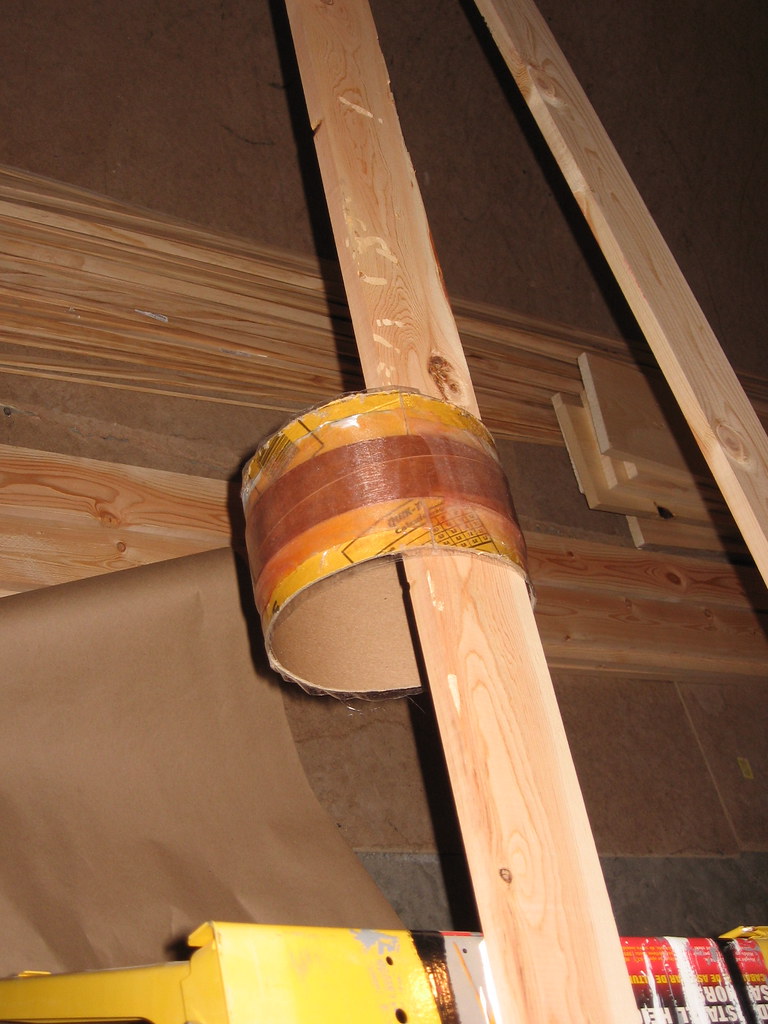
Just something I found works well for me. When glassing the tubes, instead of a round dowel to suspend the tubes, I use square wood, like a 2x2. The tubes don't rock so much and tend to be more stable while I work on them.
You are using an out of date browser. It may not display this or other websites correctly.
You should upgrade or use an alternative browser.
You should upgrade or use an alternative browser.
Level 3 Build Diary
- Thread starter dixontj93060
- Start date
Help Support The Rocketry Forum:
This site may earn a commission from merchant affiliate
links, including eBay, Amazon, and others.
dixontj93060
Well-Known Member
- Joined
- Feb 19, 2009
- Messages
- 13,083
- Reaction score
- 45
fox_racing_guy,
Thanks. I'll let her know.
She's pretty special. And has even been attending a few launches lately (see attached of her helping me prep a rocket on the pad about a month ago).
-Tim

Thanks. I'll let her know.
She's pretty special. And has even been attending a few launches lately (see attached of her helping me prep a rocket on the pad about a month ago).
-Tim
Thats the absolute best amateur boxstiching I've ever seen, you wife should be very proud!
dixontj93060
Well-Known Member
- Joined
- Feb 19, 2009
- Messages
- 13,083
- Reaction score
- 45
Handeman,
Good point. As you can see I ran out of dowels and was using a piece of flat metal shelving material for one of the tubes. That position is much more stable. I haven't started glassing yet. I think I'll do as you suggest.
-Tim
Good point. As you can see I ran out of dowels and was using a piece of flat metal shelving material for one of the tubes. That position is much more stable. I haven't started glassing yet. I think I'll do as you suggest.
-Tim
Just something I found works well for me. When glassing the tubes, instead of a round dowel to suspend the tubes, I use square wood, like a 2x2. The tubes don't rock so much and tend to be more stable while I work on them.
Last edited:
dixontj93060
Well-Known Member
- Joined
- Feb 19, 2009
- Messages
- 13,083
- Reaction score
- 45
Lee,
Yes. Sorry it wasn't more clear. Stack up is as follows:
Even though I sanded all surfaces with 80 grit before I started, the 6oz glass is there for more texture/grip/edges for epoxy adhesion. Plus the diversity of materials/structures is desirable in an effort to dampen potential oscillation/flutter.
Probably better to give you a final weight when I get done trimming and sanding the edges, but they aren't light. The Rocksim file has my pre-build estimates which should be pretty close to the finished weight at just under 31oz. per fin for the fore fins and just under 21 oz. per fin for the aft fins (33% less--must have done my math right") ).
).
Correction: the Rocksim weights include tip-to-tip CF and FG after assembly so the fin weight alone will be less.
-Tim
Yes. Sorry it wasn't more clear. Stack up is as follows:
1/16 in. ply<->6 oz. glass<->1/8 in. G10 core<->6 oz. glass<->1/16 in. ply
Even though I sanded all surfaces with 80 grit before I started, the 6oz glass is there for more texture/grip/edges for epoxy adhesion. Plus the diversity of materials/structures is desirable in an effort to dampen potential oscillation/flutter.
Probably better to give you a final weight when I get done trimming and sanding the edges, but they aren't light. The Rocksim file has my pre-build estimates which should be pretty close to the finished weight at just under 31oz. per fin for the fore fins and just under 21 oz. per fin for the aft fins (33% less--must have done my math right
).Correction: the Rocksim weights include tip-to-tip CF and FG after assembly so the fin weight alone will be less.
-Tim
Tim
Build is looking great!! On the fins, did you put a layer of cloth between the G10 and the plywood skins. Also do you have a weight yet for the fins (oz/sqin or similar ratio. On the loops, they look good. I have been taking my nylon to a shoe repair store for years and doing the same thing. About a year ago I had a testing lab pull a sample to failure and as best as I can remember it was around 1300lbs. Well good luck and keep the pictures coming!!
Last edited:
dixontj93060
Well-Known Member
- Joined
- Feb 19, 2009
- Messages
- 13,083
- Reaction score
- 45
Lee,
On your pull test, what was the failure mode? If the loop, what type of thread were you using? Kevlar? Nylon? Polyester? Was it 1" TN?
-Tim
On your pull test, what was the failure mode? If the loop, what type of thread were you using? Kevlar? Nylon? Polyester? Was it 1" TN?
-Tim
About a year ago I had a testing lab pull a sample to failure and as best as I can remember it was around 1300lbs. Well good luck and keep the pictures coming!!
I'll bet a shiny nickel that ground testing will show your 2.25g
calculated apogee charge to be too small for good separation.
2.25 seems light given your heavy harness, 4' drogue, and shear pins.
Beautiful stitching on the harness. Would have guessed professional.
calculated apogee charge to be too small for good separation.
2.25 seems light given your heavy harness, 4' drogue, and shear pins.
Beautiful stitching on the harness. Would have guessed professional.
dixontj93060
Well-Known Member
- Joined
- Feb 19, 2009
- Messages
- 13,083
- Reaction score
- 45
mIcahel,
I do believe you are right. Typically the calculations I do tend to provide a minimum floor value and then I ground test like crazy to get to the performance I like to see--normally move up 0.5 to 1 gram on each charge.
-Tim
I do believe you are right. Typically the calculations I do tend to provide a minimum floor value and then I ground test like crazy to get to the performance I like to see--normally move up 0.5 to 1 gram on each charge.
-Tim
I'll bet a shiny nickel that ground testing will show your 2.25g
calculated apogee charge to be too small for good separation.
2.25 seems light given your heavy harness, 4' drogue, and shear pins.
Beautiful stitching on the harness. Would have guessed professional.
dixontj93060
Well-Known Member
- Joined
- Feb 19, 2009
- Messages
- 13,083
- Reaction score
- 45
Lee,
I have your number. I trimmed and sanded the edges on two fins, one small (aft), one large (fore). Ratios were the same so I'll just give you the aft:
Of course, when I bevel the fins, they will weigh less, but I think this is the measurement you wanted.
-Tim
P.S. "Mileage may vary"
P.P.S. Interesting to compare this measurement to Greg's recently posted density table. At 0.31 in. thick the finished fins are 0.044 lb./cubic in. or 33% lighter than G10 of the same volume.
I have your number. I trimmed and sanded the edges on two fins, one small (aft), one large (fore). Ratios were the same so I'll just give you the aft:
17.6 oz. / 79.64 sq. in. = 0.22 oz./sq. in.
Of course, when I bevel the fins, they will weigh less, but I think this is the measurement you wanted.
-Tim
P.S. "Mileage may vary"
P.P.S. Interesting to compare this measurement to Greg's recently posted density table. At 0.31 in. thick the finished fins are 0.044 lb./cubic in. or 33% lighter than G10 of the same volume.
Also do you have a weight yet for the fins (oz/sqin or similar ratio.
Last edited:
dixontj93060
Well-Known Member
- Joined
- Feb 19, 2009
- Messages
- 13,083
- Reaction score
- 45
As Ricky Bobby would say, "We're now tuned in to the PBS Channel..." (Pretty Boring Stuff--although he probably wouldn't say "stuff").
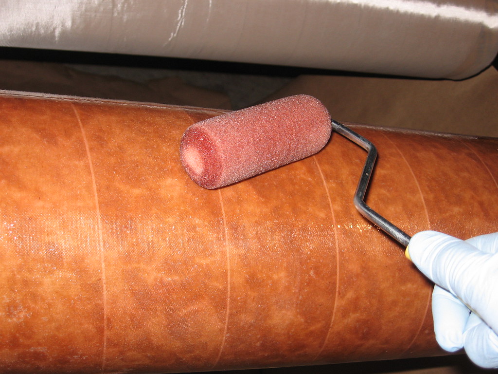
In any case the lay up of the body tubes is presented for completeness. Applying epoxy to wet out the first layer:
Here is the first tube, first layer complete:
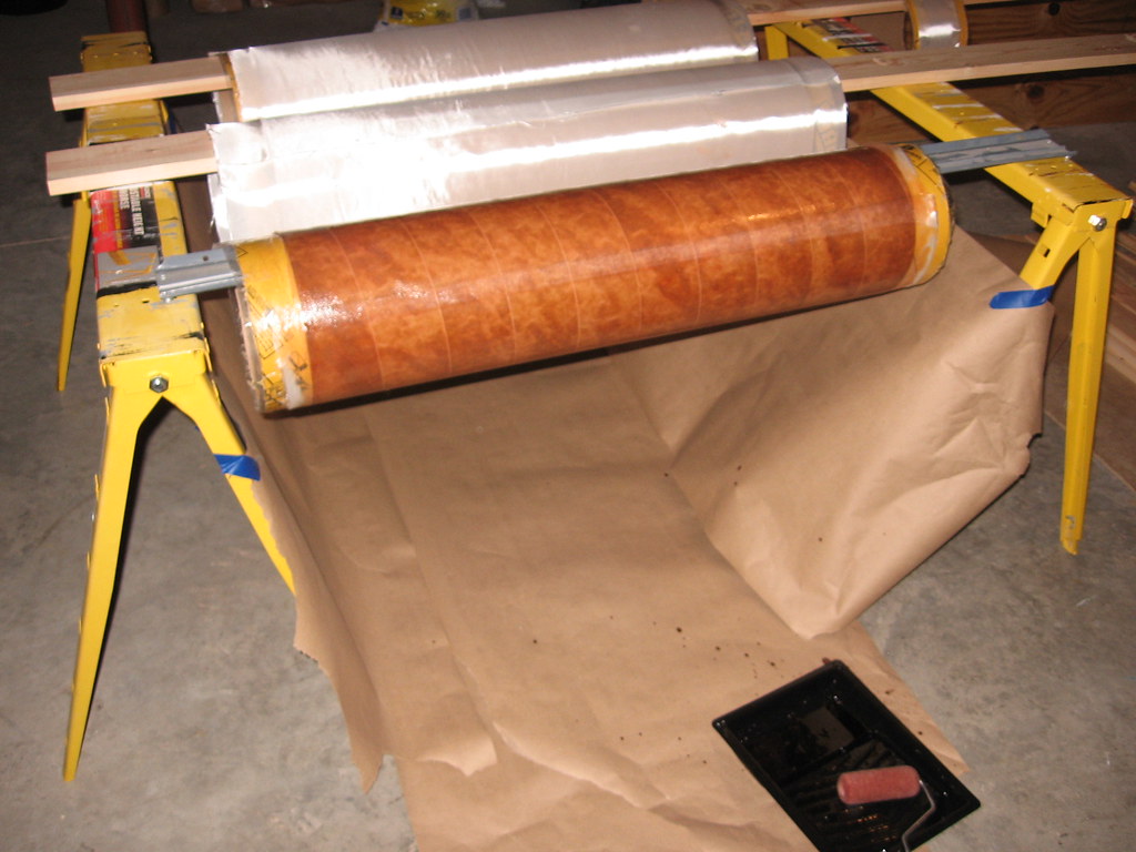
If I haven't mentioned it before, I am using West System 105/205 for the lay ups and areas where I need a longer cure epoxy. For structural adhesion I am using T-88, and where I just need to tack things quickly, then Quickcure 5 both from System Three.
In any case the lay up of the body tubes is presented for completeness. Applying epoxy to wet out the first layer:
Here is the first tube, first layer complete:
If I haven't mentioned it before, I am using West System 105/205 for the lay ups and areas where I need a longer cure epoxy. For structural adhesion I am using T-88, and where I just need to tack things quickly, then Quickcure 5 both from System Three.
Last edited:
dixontj93060
Well-Known Member
- Joined
- Feb 19, 2009
- Messages
- 13,083
- Reaction score
- 45
Of course, can't forget the avionics bay spacer:
All this work wears you out. Obligatory pic of my favorite libation. Of course, this isn't the preferred drink of most TRF'rs, but hey, living in Silicon Valley for some time in the Santa Cruz mountains a few miles from two great wineries, I grew accustom to it.

BTW, if you can read the etching on the cup, "Stone's Throw Winery" is one of the best wineries in the Midwest. Right in the center of Door County in Wisconsin. If you get a chance to visit, I'd recommend it highly.
All this work wears you out. Obligatory pic of my favorite libation. Of course, this isn't the preferred drink of most TRF'rs, but hey, living in Silicon Valley for some time in the Santa Cruz mountains a few miles from two great wineries, I grew accustom to it.
BTW, if you can read the etching on the cup, "Stone's Throw Winery" is one of the best wineries in the Midwest. Right in the center of Door County in Wisconsin. If you get a chance to visit, I'd recommend it highly.
dixontj93060
Well-Known Member
- Joined
- Feb 19, 2009
- Messages
- 13,083
- Reaction score
- 45
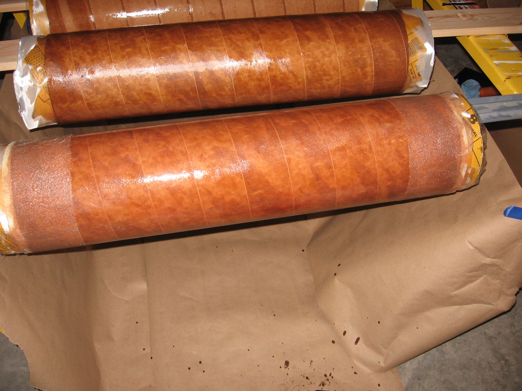
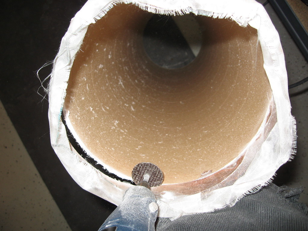
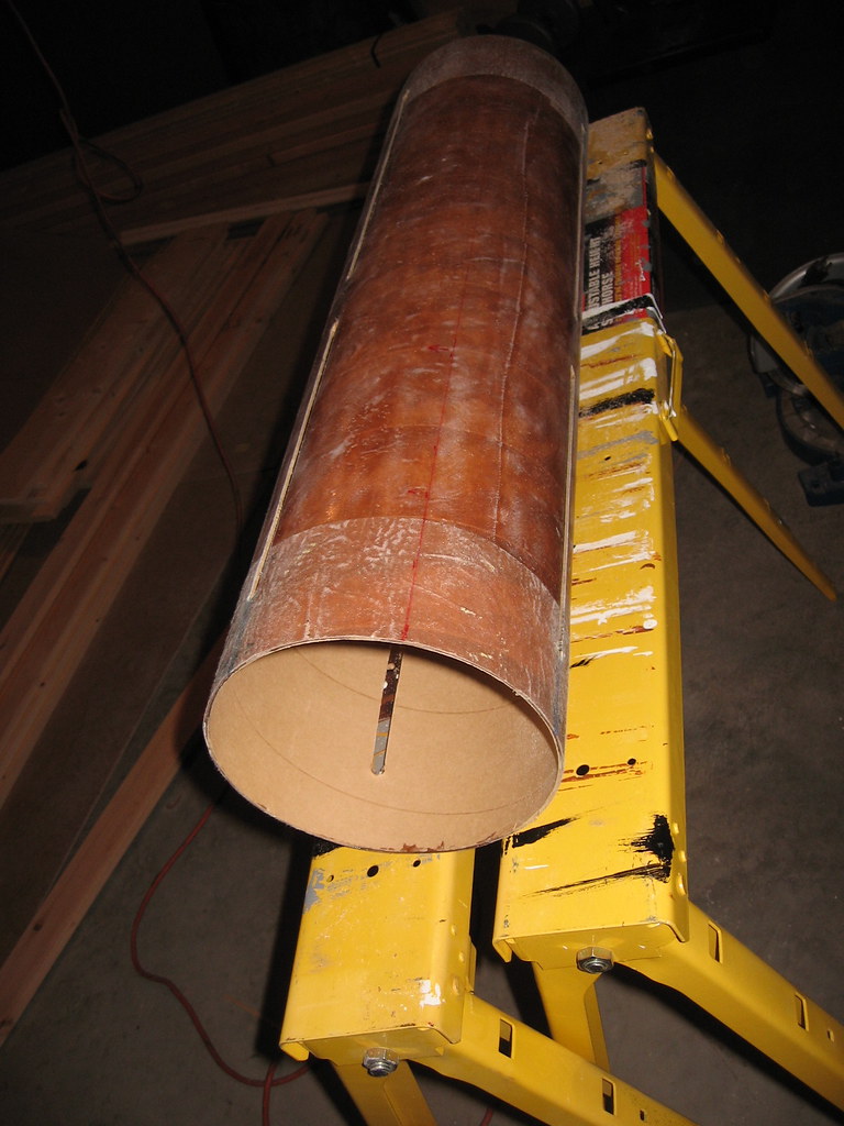
Headed down the home stretch... Picture is of completed second layer on the first tube (I really hate laying down the cross ply layer as it stretches all over the place!). Of note is the kevlar mat on both ends to strengthen the critical attach and shear points on the tube. Note that it looks a bit "furry", that's just the nature of the beast. Remember, there will still be one more 3 oz. veil layer of S-glass applied at a later stage which will hide/smooth this out.
Enough for now. My family and I are headed out today for a ski trip. I wish the best for you and yours this time of year also!
Enough for now. My family and I are headed out today for a ski trip. I wish the best for you and yours this time of year also!
Last edited:
tomar
Well-Known Member
- Joined
- Mar 23, 2009
- Messages
- 87
- Reaction score
- 0
Headed down the home stretch... Picture is of completed second layer on the first tube (I really hate laying down the cross ply layer as it stretches all over the place!). Of note is the kevlar mat on both ends to strengthen the critical attach and shear points on the tube. Note that it looks a bit "furry", that's just the nature of the beast. Remember, there will still be one more 3 oz. veil layer of S-glass applied at a later stage which will hide/smooth this out.
Enough for now. My family and I are headed out today for a ski trip. I wish the best for you and yours this time of year also!
Is there any reason you did not put the Kevlar mat on before the fiberglass. I think it would provide the same strength AND allow the next layer(s) of glass to "smoothen" out the ridge better. There is nothing wrong with your technique and you will have a nicely laminated rocket.
I do notice a slight redish-brown color to the epoxy. Is the hardner old? My 205 hardner started turning dark after about 4 years. I got my 205 and 206 hardners at the same time and the 205 is definately darker that the 206. I checked with West System and they said that while it is not unusual for the hardners to turn dark, it does not compromise the strength of cured epoxy.
It looks very good. I've done fiberglass laminations for years and I still learn stuff from reading of other's experiences.
Thanks for sharing.
dixontj93060
Well-Known Member
- Joined
- Feb 19, 2009
- Messages
- 13,083
- Reaction score
- 45
Mark,
Uhhh... Well, to be honest this is one of my typical screw ups I mentioned in my first post. It was late last night (after 1am) when I did the second lay up and yes, I was going to put the kevlar between the two 6 oz. layers, but forgot on the first tube. Given that I have a final veil layer and I do some pretty extensive filling with Super Fil afterwards, I believe it will still turn out looking fine.
The epoxy is about three years old--well at least 3/4rs of it. I was going to use some new US Composites Medium cure I have, but in doing inventory before starting the build, I noticed I had a pretty full container of 205, so I checked with manager at the local West Marine store and they said it would be fine so I bought a small can of 205 and mixed it to top it off along with a new gallon of 105. I'll go ahead and finish all the West System off before opening the US Composites for future builds.
-Tim
Is there any reason you did not put the Kevlar mat on before the fiberglass. I think it would provide the same strength AND allow the next layer(s) of glass to "smoothen" out the ridge better. There is nothing wrong with your technique and you will have a nicely laminated rocket.
I do notice a slight redish-brown color to the epoxy. Is the hardner old? My 205 hardner started turning dark after about 4 years. I got my 205 and 206 hardners at the same time and the 205 is definately darker that the 206. I checked with West System and they said that while it is not unusual for the hardners to turn dark, it does not compromise the strength of cured epoxy.
It looks very good. I've done fiberglass laminations for years and I still learn stuff from reading of other's experiences.
Thanks for sharing.
Last edited:
tomar
Well-Known Member
- Joined
- Mar 23, 2009
- Messages
- 87
- Reaction score
- 0
I don't know what you guys do, but I build/reinforce my mandrels with packing tape inside and out. It makes them hold form, but also provides adequate release from the epoxy after fiberglassing.
I've never used your mandrel method. I've always used 2" wide masking tape on the inside of the tube opening.
How easily do your mandrels come out? Could you break the mandrel at the seam to get them out?
dixontj93060
Well-Known Member
- Joined
- Feb 19, 2009
- Messages
- 13,083
- Reaction score
- 45
Yes, that's right. You put a bit of pressure on the seam and they pop right out. They come out intact and you could use them over again if needed.
I like using the mandrels as they are pretty substantial, putting pressure from the inside helping assure a true circle at the opening when the tubes have been hanging there wet for 8 or 10 hours.
I like using the mandrels as they are pretty substantial, putting pressure from the inside helping assure a true circle at the opening when the tubes have been hanging there wet for 8 or 10 hours.
I've never used your mandrel method. I've always used 2" wide masking tape on the inside of the tube opening.
How easily do your mandrels come out? Could you break the mandrel at the seam to get them out?
dixontj93060
Well-Known Member
- Joined
- Feb 19, 2009
- Messages
- 13,083
- Reaction score
- 45
Quick update and a few more pics...
But first, I do apologize, the build is going a bit slower than expected for two reasons:

But first, I do apologize, the build is going a bit slower than expected for two reasons:
- I am violating #4 in my ground rules and am answering questions in detail either through a PM or email (which I doubt I'll be able to keep up and still get the build done by March). Most specifically a couple of folks have questions on the fin stack up and flutter simulation. I use/have used in the past conservative estimates/values for the build up based on discussions with AeroFinSim. I am now doing rigorous laminate analysis to verify the performance of the fins. This takes time in two main areas: first, finding the simulations tools to do the in depth analysis, and second tracking down the material parameters and/or test results from which the parameters can be derived (BTW, the U.S. Government seems to have a beaucoup of analysis of materials done in the 50's and 60's). In any case, I've spent the better part of two days doing the above and am getting close. Preliminary results confirm the conservative estimates and the fin performance looks to be better than originally reported. (Note: the funny thing is that the folks that bring up the questions/concerns seem to either not want to, or can't do, the underlying math and/or don't want to spend the money on simulation/analysis tools to support their assertions, oh well, such is life).
- Also I did have to spend one night helping my son that is home from college on his "Mad Max" pocket rocket (see pic). Of course, given his age, it took him a while to "get" the reference to Mad Max.
dixontj93060
Well-Known Member
- Joined
- Feb 19, 2009
- Messages
- 13,083
- Reaction score
- 45
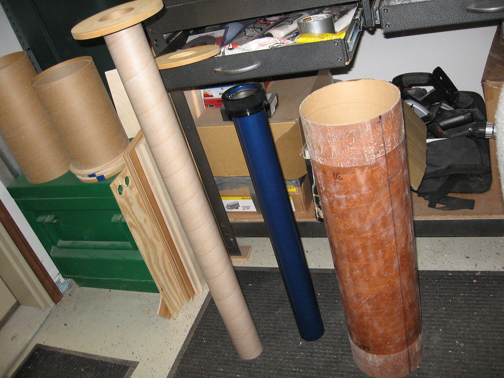
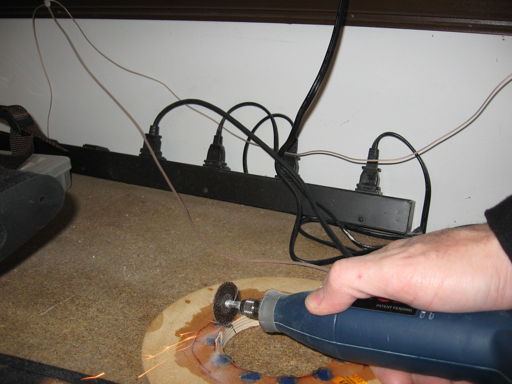
Trimming and marking the body tubes is next on my agenda.
Below I'm trimming off the excess fiberglass/kevlar material. It seems like many folks mark the tubes from the outside and cut--I don't. Instead I just take a Dremel and trim from the inside at a slight angle right at the edge of the inside of the BT. You have to have a steady hand, but generally I have found it very quick and easy.
Before long, all tubes trimmed and sanded square:
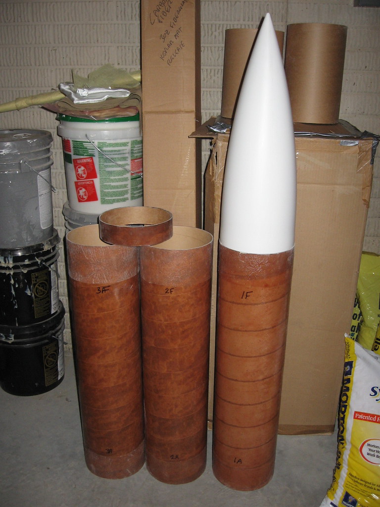
Last edited:
dixontj93060
Well-Known Member
- Joined
- Feb 19, 2009
- Messages
- 13,083
- Reaction score
- 45
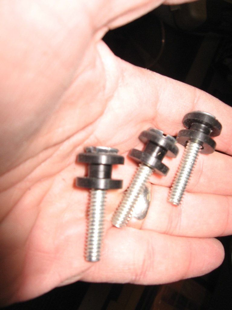
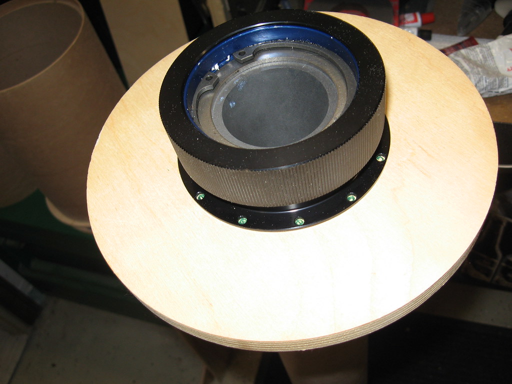
Found a bit of time to address a quirk of mine... I hate having massive screw heads sticking out of rail buttons so I typically counter sink flat head screws for attachment (Note: shown are some standard zinc plated 1/4-20 screws for the 1515 buttons, but I'll probably get some black oxide socket caps for the final assembly).
dixontj93060
Well-Known Member
- Joined
- Feb 19, 2009
- Messages
- 13,083
- Reaction score
- 45
Now on to marking fins and CRs... Like many of you, I find it convenient to use the BSD fin template to mark my BT's (Note: file attached, but also note that it is a .pdf file and you have to print it out "without scaling" which doesn't seem to be the default for Adobe--if not, you will mark your fins incorrectly).
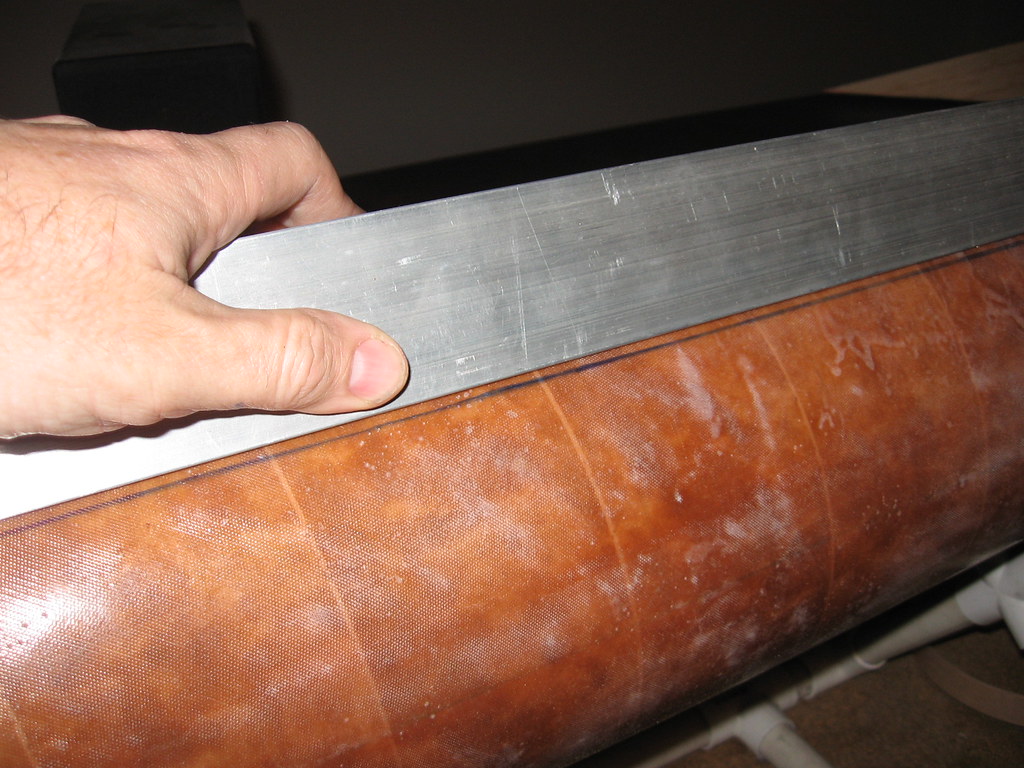
After marking the ends, the typical use of angle stock to mark the length of the tube. Big tube, big angle stock.
As a final step I use my wife's sewing tape measure and verify spacing all around the tube diameter and length (not shown).
View attachment fin_guide.pdf
After marking the ends, the typical use of angle stock to mark the length of the tube. Big tube, big angle stock.
As a final step I use my wife's sewing tape measure and verify spacing all around the tube diameter and length (not shown).
View attachment fin_guide.pdf
Last edited:
dixontj93060
Well-Known Member
- Joined
- Feb 19, 2009
- Messages
- 13,083
- Reaction score
- 45
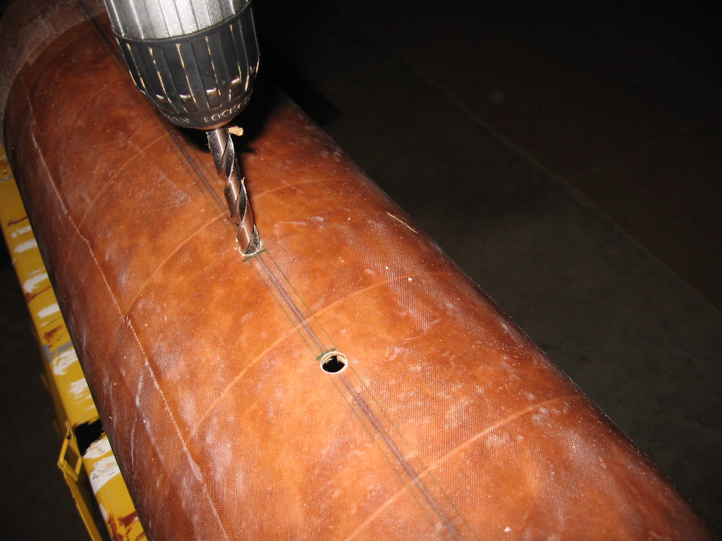
After marking the tubes, it's on to marking the CR's for both the all-thread and retainer attachment. To make sure I get this right, it gives me a chance to pull out the "big iron" which is always a joy during a build.
Last edited:
dixontj93060
Well-Known Member
- Joined
- Feb 19, 2009
- Messages
- 13,083
- Reaction score
- 45
I won't bore you with all the marking pictures. Here's one marking the motor retainer T-nut locations. After all the marking was completed last night, I stopped. Over many builds (and associated mistakes), I have found it better not to mark and cut/drill on the same night. So I mark and then cut/drill after a bit of time has passed just to give all my measures/steps time to gestate in my head a bit--really cuts down on the errors.
DAllen
Well-Known Member
I've seen people do this and have always wondered...Why 3 buttons? 2 will work just fine where 3 will be really annoying to line up and just cause more friction on liftoff. I've seen oodles and oodles of M and N powered projects on the 1515 rails work just fine with 2 buttons.
-Dave
-Dave
dixontj93060
Well-Known Member
- Joined
- Feb 19, 2009
- Messages
- 13,083
- Reaction score
- 45
Dave,
To each his own I guess...
I will tell you I was glad to have three on my L2 project (small ones--see pic). It only weighed 18 lbs, but when loading the Pad Manager dropped the rail by mistake just as I began sliding it on. Cranked the bottom button and it popped right off and stripped the screw (actually my fault probably as the bottom screw was too short given the tip-to-tip build up and it only caught on the last few threads). In any case, I was able to continue to load with the two remaining buttons. Of course, I have loaded it a number of times since and haven't had that problem.
Also have never had any issues lining three buttons up--pretty straight-forward really.
-Tim
I've seen people do this and have always wondered...Why 3 buttons? 2 will work just fine where 3 will be really annoying to line up and just cause more friction on liftoff. I've seen oodles and oodles of M and N powered projects on the 1515 rails work just fine with 2 buttons.
-Dave
Last edited:
tomar
Well-Known Member
- Joined
- Mar 23, 2009
- Messages
- 87
- Reaction score
- 0
You may already know this, but I'll pass it on anyway. When putting in the socket head screws, use a ball end hex key, like this one https://www.grainger.com/1/1/34496-eklind-61806-hex-key-ball-end-3-32-pk-4.html, so you can angle the driver off 90 degrees a little. The location of the flange holes is so close to the edge of the threads it is easy to deform the threads of the retainer with a straight hex key, making it hard to screw on the retainer later. Take it from me (personal experience).
Looking good so far.
Looking good so far.
dixontj93060
Well-Known Member
- Joined
- Feb 19, 2009
- Messages
- 13,083
- Reaction score
- 45
Mark,
Thanks for the tip!
-Tim
Thanks for the tip!
-Tim
You may already know this, but I'll pass it on anyway. When putting in the socket head screws, use a ball end hex key, like this one https://www.grainger.com/1/1/34496-eklind-61806-hex-key-ball-end-3-32-pk-4.html, so you can angle the driver off 90 degrees a little. The location of the flange holes is so close to the edge of the threads it is easy to deform the threads of the retainer with a straight hex key, making it hard to screw on the retainer later. Take it from me (personal experience).
Looking good so far.
dixontj93060
Well-Known Member
- Joined
- Feb 19, 2009
- Messages
- 13,083
- Reaction score
- 45
O.K., let's finish out the year with a bit of drilling and cutting...
First scoring the inside and outside of all the CR's to get an extra bit of surface bite for the epoxy.
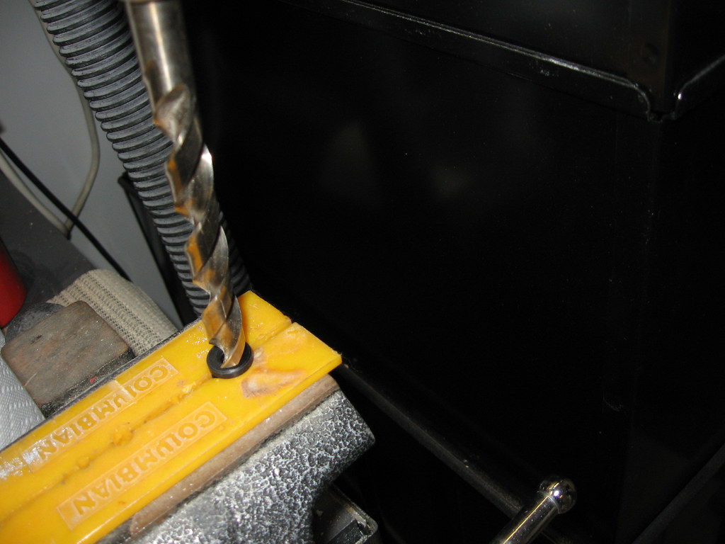
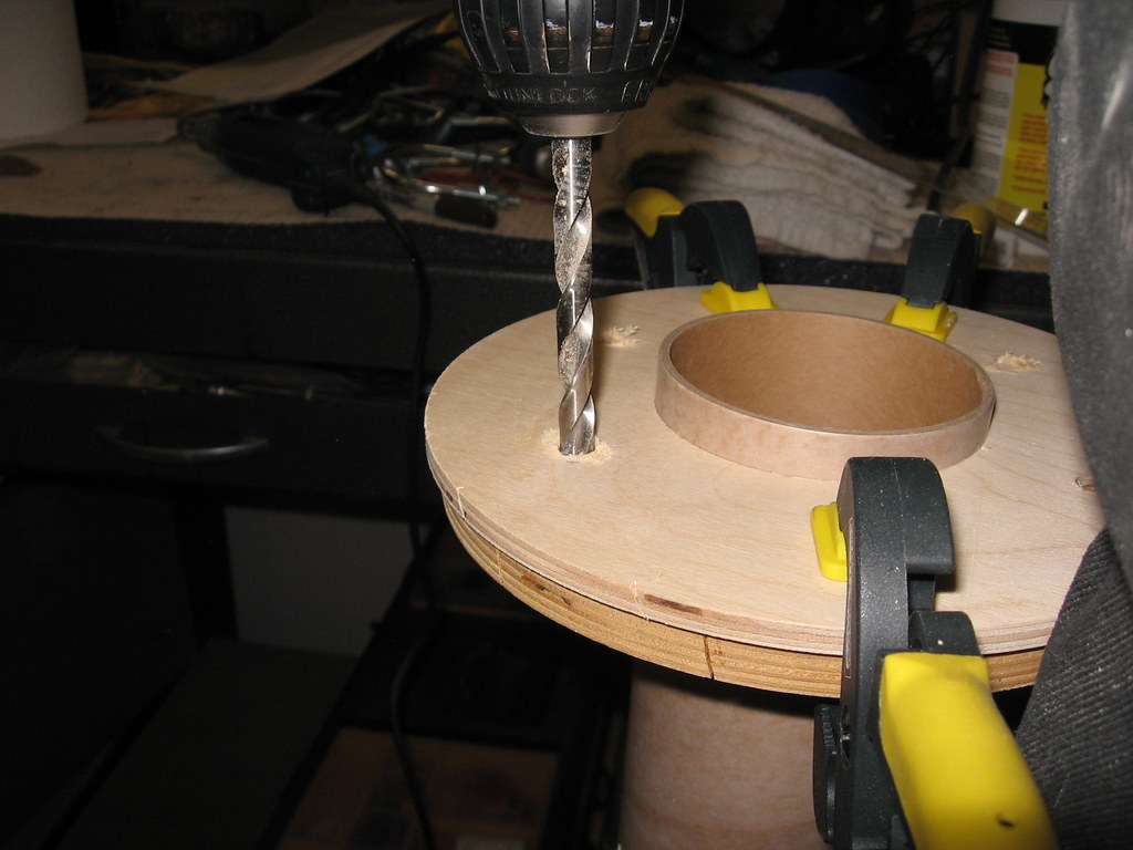
Then clamping and drilling the fore and mid-fore MMT CR's for all-thread/U-bolts.
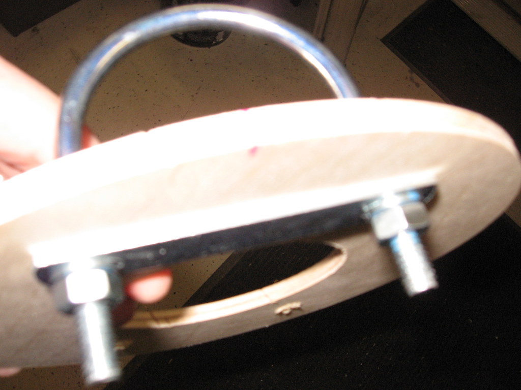
One of the two U-bolt attached for the fore end of the booster (bad picture, but you may notice the blue thread lock--will add epoxy set later).
First scoring the inside and outside of all the CR's to get an extra bit of surface bite for the epoxy.
Then clamping and drilling the fore and mid-fore MMT CR's for all-thread/U-bolts.
One of the two U-bolt attached for the fore end of the booster (bad picture, but you may notice the blue thread lock--will add epoxy set later).
dixontj93060
Well-Known Member
- Joined
- Feb 19, 2009
- Messages
- 13,083
- Reaction score
- 45
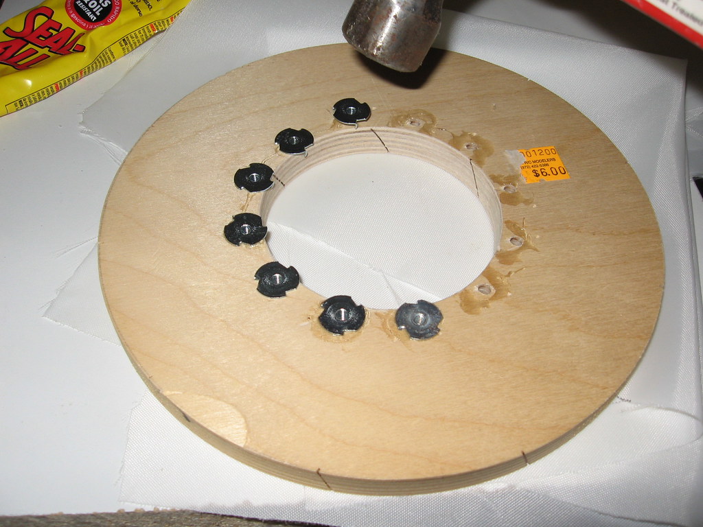
Twelve locations previously marked on aft CR for Aeropack retainer are drilled out and T-nuts inserted (using a bit of contact cement to hold in place as I lightly tap and adjust to make sure all inserted screws are 90 degrees all around).
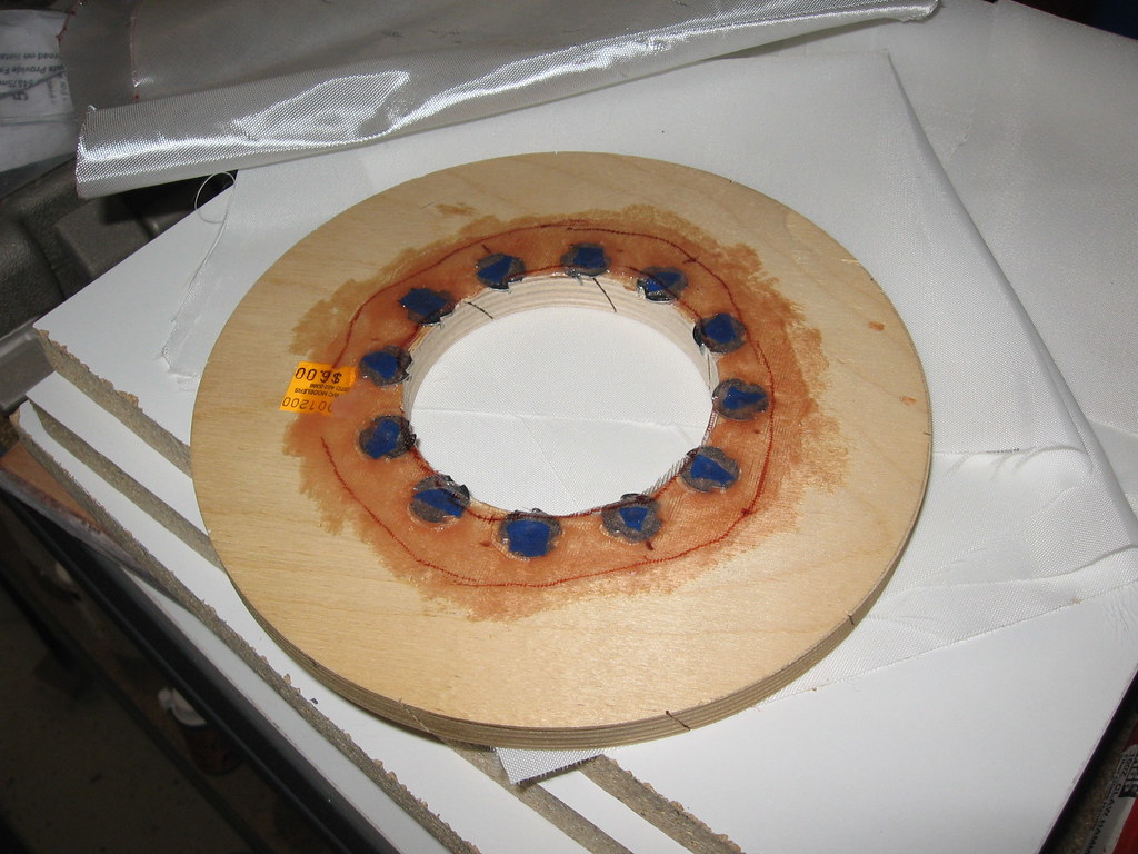
Then cut a ring of 6 ounce fiberglass, and wet out on the back of the T-nuts for extra security (Note: holes are covered with blue masking tape).
After drying overnight a test fit and all 12 screws fit great!
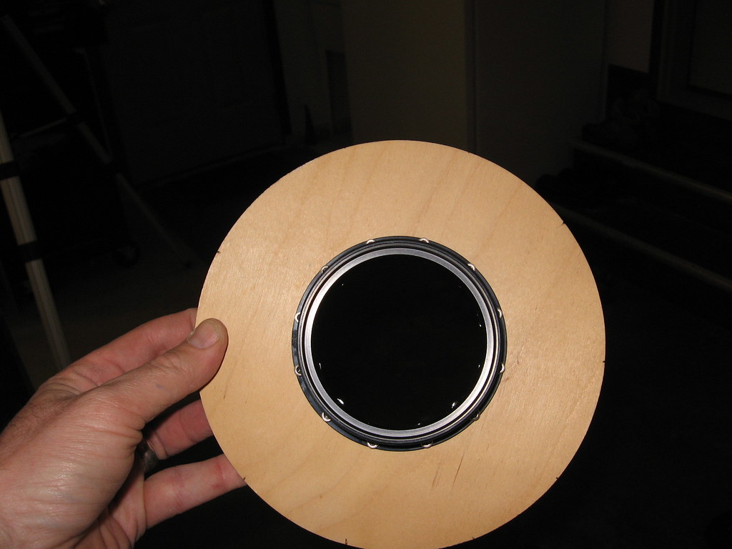
Now just trimming the slight overhang of the T-nuts and final filing to fit MMT.
Then cut a ring of 6 ounce fiberglass, and wet out on the back of the T-nuts for extra security (Note: holes are covered with blue masking tape).
After drying overnight a test fit and all 12 screws fit great!
Now just trimming the slight overhang of the T-nuts and final filing to fit MMT.
dixontj93060
Well-Known Member
- Joined
- Feb 19, 2009
- Messages
- 13,083
- Reaction score
- 45
Now on to the booster tube. Carefully drilling at both ends of all six fin slots.
Then (again carefully) cutting slots.
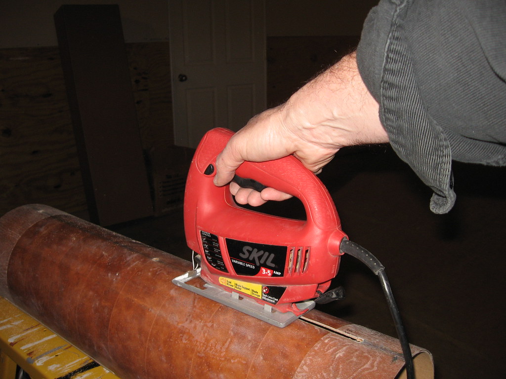
Fully cut booster where slots nearly span the full length.
Then (again carefully) cutting slots.
Fully cut booster where slots nearly span the full length.
tomar
Well-Known Member
- Joined
- Mar 23, 2009
- Messages
- 87
- Reaction score
- 0
Do you see what I mean about the threads being inline with the cap head screws in the flange?
Good work so far. The T-nuts are a good idea. The inserts are meant for adding the retainer after the the motor tube and centering rings are already in the rocket.
Good work so far. The T-nuts are a good idea. The inserts are meant for adding the retainer after the the motor tube and centering rings are already in the rocket.
dixontj93060
Well-Known Member
- Joined
- Feb 19, 2009
- Messages
- 13,083
- Reaction score
- 45
Yes, I see. Regarding the inserts--don't really like them. I used them way back on a regular clip retainer and had trouble with it loosening up so I stick with T-nuts (reinforced even).
Do you see what I mean about the threads being inline with the cap head screws in the flange?
Good work so far. The T-nuts are a good idea. The inserts are meant for adding the retainer after the the motor tube and centering rings are already in the rocket.
Similar threads
- Replies
- 74
- Views
- 5K
- Replies
- 32
- Views
- 897