You are using an out of date browser. It may not display this or other websites correctly.
You should upgrade or use an alternative browser.
You should upgrade or use an alternative browser.
How do you attach your rail buttons?
- Thread starter Lowpuller
- Start date


Help Support The Rocketry Forum:
This site may earn a commission from merchant affiliate
links, including eBay, Amazon, and others.
blackbrandt
That Darn College Student
- Joined
- Mar 18, 2012
- Messages
- 9,281
- Reaction score
- 60
I use acme rail guides, which glue to the outside of the tube.
https://giantleaprocketry.com/products/components_launch_systems.aspx#Acme_Conformal_Launch_Guides
I use epoxy to attach them to the tube.
Or you can use rail buttons, which you can find cheap here:
https://rail-buttons.com/
These screw into the centering rings.
Most small rockets use 1010 size rail, which is standard at most launch sites.
Matt
hpreric
Well-Known Member
- Joined
- Oct 11, 2013
- Messages
- 95
- Reaction score
- 0
I add a small block of wood to the upper and lower centering rings to double their thickness (it's a bigger target to hit when I drill the holes through the body tube). I then drill the holes through the body tube and mount the rail buttons using wood screws. I use 1010 rail buttons because that's what my club mainly uses, although they have 1515 rails available if you ask for one.
- Joined
- Apr 13, 2013
- Messages
- 2,441
- Reaction score
- 1,360
It depends on the weight and airframe material of the rocket, but I prefer to mount a T-nut into a small piece of plywood and mount that inside the airframe. This provides a very strong anchor.
Once again, it's not flight stresses that are the strongest forces on the rail buttons, but the torque of the rocket want to turn to the side when the rail is in the horizontal position, especially with heavy rockets.


As it happens, I was just installing the rail button mounts into my AGM-33 Pike, so I even have pictures.
Once again, it's not flight stresses that are the strongest forces on the rail buttons, but the torque of the rocket want to turn to the side when the rail is in the horizontal position, especially with heavy rockets.
As it happens, I was just installing the rail button mounts into my AGM-33 Pike, so I even have pictures.
Last edited:
All good methods and advice. I used all of those methods, or something similar at one time or another.
I have heard that some clubs won't allow the metal rail guide to be used. I've never come across that personally. Our club allows them and we've had no problems from them over the last 5 or 6 years we've been using our rails. You might want to check with the club you want to fly with just to make sure.
The standard rail is the 1.0" by 1.0" (1010) extruded aluminum T-slot framing McMaster Carr and run about $27 for a 8' piece. We launch up to K motors and 20 lbs on our 1010 pads, but what each club allows will depend on how their pads are built.
If you need something bigger, the next step up is the 1.5" by 1.5" (1515). Same thing as the 1010, just bigger.
If you need something really big, you use the strut channel. We only have that on our trailer launcher which is used for all L3 and/or +40 lb rockets.
4kids49
Taz
- Joined
- Jul 29, 2012
- Messages
- 1,058
- Reaction score
- 2
For years I have just drilled a hole and screwed them in. Paper, quantum, blue tube, phenolic, fiberglass...doesn't matter.
+1 on this method. If people want something additional to screw into, but don't want to go into centering rings, these rail buttons from Apogee work well. Basically drill hole, pop in nut inside of tube and through airframe, screw in button.
https://www.apogeerockets.com/index..._supplies_info&cPath=42_72_77&products_id=173
TopRamen
SA-5
- Joined
- Aug 9, 2013
- Messages
- 9,955
- Reaction score
- 112
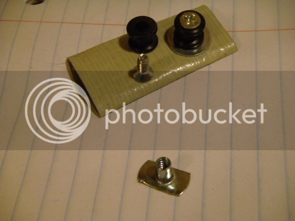
I've only used 1010 Rail Buttons, and I do them like this. I trimmed down the sides of the Nut so that they don't warp the Body Tube when you tighten them down. It has come to my attention that these can be had from Mcmaster Carr or someplace like that. Some folks like em' to spin freely, but I do not.

Right Wing Wacko
Well-Known Member
- Joined
- Apr 8, 2012
- Messages
- 193
- Reaction score
- 0
I belong to one of those clubs that does not allow metal rail buttons on club equipment because of the extra wear on the Rail's, so I use standard rail buttons screwed into wood centering rings or with a weld nut to hold it on.
Last edited:
Lowpuller
Well-Known Member
- Joined
- Nov 22, 2013
- Messages
- 2,230
- Reaction score
- 26
Awesome answers and thank you everyone that took pictures.
Since this is going good, I'll keep asking.
How do you align your rail buttons, especially if you are using launch lugs. It appears to me that the slightest misalignment of a metal lug on a metal rail is a friction monster??
Since this is going good, I'll keep asking.
How do you align your rail buttons, especially if you are using launch lugs. It appears to me that the slightest misalignment of a metal lug on a metal rail is a friction monster??
blackbrandt
That Darn College Student
- Joined
- Mar 18, 2012
- Messages
- 9,281
- Reaction score
- 60
Angle Iron. It lays straight on the tube.
The Rubber-Insulated Rivet nuts from McMaster Carr work great. At 60 - 70 cents apiece, they aren't too expensive either.
Matt Galloway
New Member
My rocket is made from a phenolic tube. I have the Delrin 2 piece rail button. Has anyone tried drilling & taping the tube? Is that strong enough without a blind nut or some other retainer?
- Joined
- Apr 13, 2013
- Messages
- 2,441
- Reaction score
- 1,360
If the rocket is very light it could be OK, but I would back up the screw with something inside the airframe if you can.My rocket is made from a phenolic tube. I have the Delrin 2 piece rail button. Has anyone tried drilling & taping the tube? Is that strong enough without a blind nut or some other retainer?
- Joined
- Jan 16, 2015
- Messages
- 271
- Reaction score
- 66
acorn nut epoxied into place on the inside, held in place with the rail-button. After remove rail-button and continue to build, paint rocket, add button when all done.
SteveThatcher
SMT Designs
acorn nut epoxied into place on the inside, held in place with the rail-button. After remove rail-button and continue to build, paint rocket, add button when all done.
I used to use Pem nuts and actually press them into the air frame wall and epoxy them so they wouldn't fall out. It is always nice to be able to remove the guides to replace when necessary.
Nytrunner
Pop lugs, not drugs
Weld nuts (like T-nuts without the prongs)
I love those things almost as much as rivets
I love those things almost as much as rivets
SteveThatcher
SMT Designs
Weld nuts (like T-nuts without the prongs)
I love those things almost as much as rivets
I wanted something that was low profile and they certainly did fit the bill. They did take multiple steps in the build process though...
")
heada
Well-Known Member
Centering rings. I use the aft CR and the most forward CR. Drill through the bodytube and into the ring, soak with thin CA and then tap it. Then when installing the rail button, I use CA on the threads of the screw. Tighten until the button is snug and doesn't rotate and then back off 1/8th of a turn so that it rotates freely. I normally use longer MMTs and place my forward CR higher than normal but even with this, I have room for a shock cord and drogue between the forward CR and the e-bay. By using the CRs, I feel they're stronger than nothing but at the same time, easier than an acorn nut/well nut and nothing for the recovery harness to catch on.
Nytrunner
Pop lugs, not drugs
I noted the same, but new person deserves new answers. He never stated what size the rocket is, so in true TRF fashion, multiple unsolicited alternatives have been presented in case they're helpful! I love this place
- Joined
- Oct 2, 2011
- Messages
- 974
- Reaction score
- 543
It depends on the weight and airframe material of the rocket, but I prefer to mount a T-nut into a small piece of plywood and mount that inside the airframe. This provides a very strong anchor.
Once again, it's not flight stresses that are the strongest forces on the rail buttons, but the torque of the rocket want to turn to the side when the rail is in the horizontal position, especially with heavy rockets.
View attachment 155391 View attachment 155392
As it happens, I was just installing the rail button mounts into my AGM-33 Pike, so I even have pictures.
John, in the photos... what is the purpose of the section of coupler tube inside the fiberglass airframe. Almost looks like the ring buts up against the through the wall fins.
Like you put it there to assist the transfer of thrust load to the airframe through the fins.
Paul
- Joined
- Apr 13, 2013
- Messages
- 2,441
- Reaction score
- 1,360
I used 2-part foam to solidify the fin can and because you have to work fast once you pour the foam, I wanted the aft CR to be able to be pushed into place and held without a lot of fiddling. By having a ring bonded inside, I could put in the epoxy, pour in the foam, and the push in the aft CR until it bottomed out on the ring.John, in the photos... what is the purpose of the section of coupler tube inside the fiberglass airframe. Almost looks like the ring buts up against the through the wall fins.
Like you put it there to assist the transfer of thrust load to the airframe through the fins.
- Joined
- Oct 2, 2011
- Messages
- 974
- Reaction score
- 543
Ahh I see ….
Thank you ……….
Thank you ……….
Similar threads
- Replies
- 1
- Views
- 430