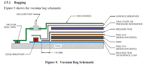
Gas Gas Gas: I'm gonna run as a flash!
The goal is to fly it on the H999 and the I1299.


Most of the parts come from a Darkstar Mini I got from https://eurospacetechnology.eu/index.php.
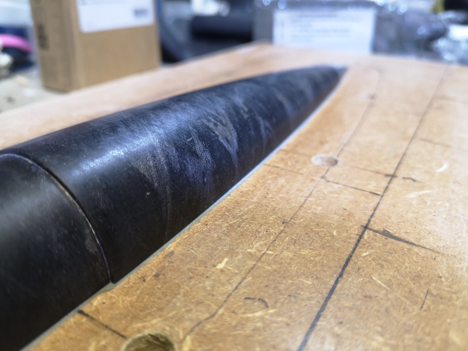
I will be using: the body tube with the slotted section removed, the nosecone, fins as stock to make the bulkheads, shock cord, and parachute.
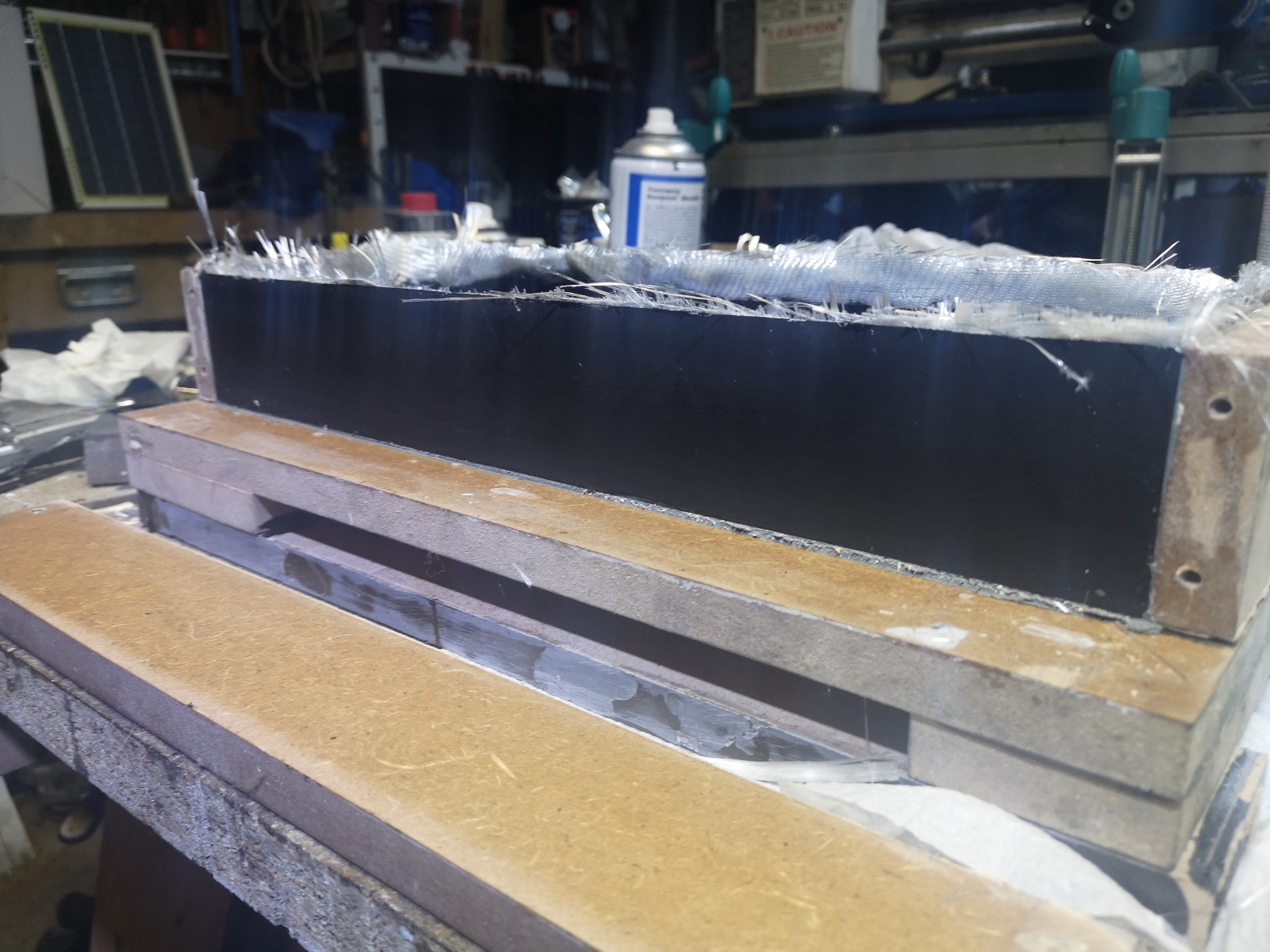
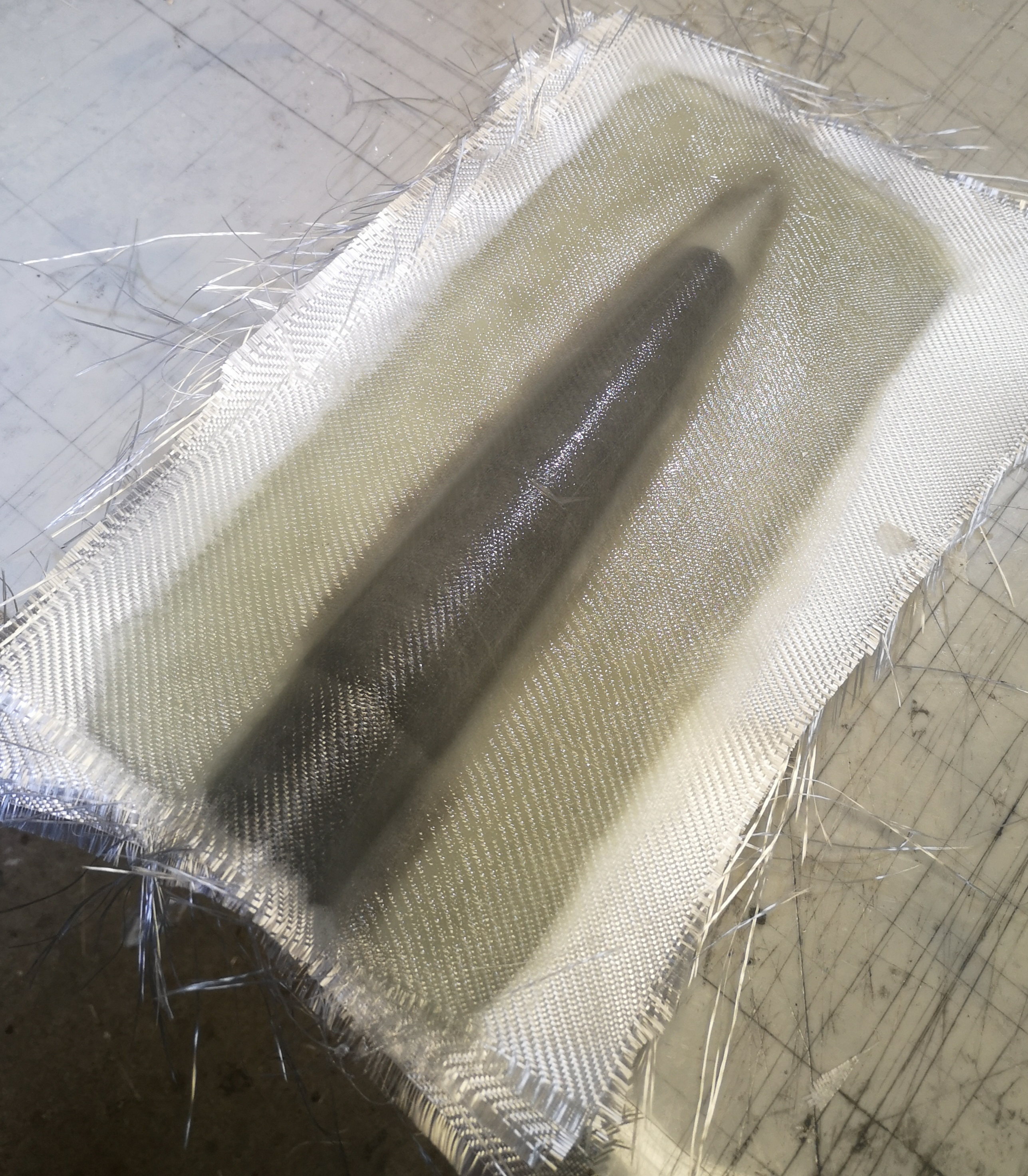
The part between the end of the casing and the nosecone shoulder will be supported by a piece of fiberglass coupler as a sanity check.
Motor retention: threaded Aerotech closure + bulkhead on the stiffening coupler.
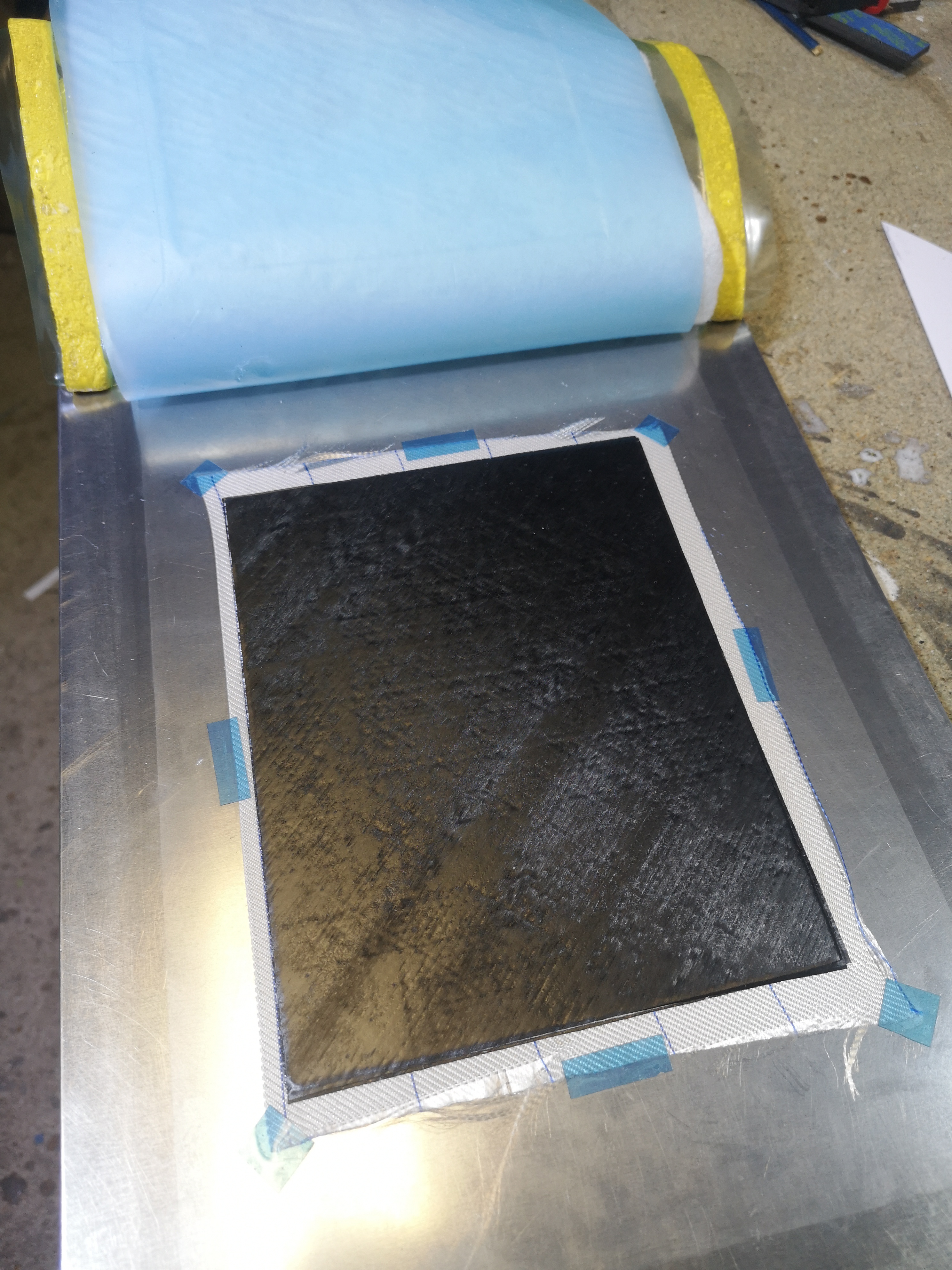
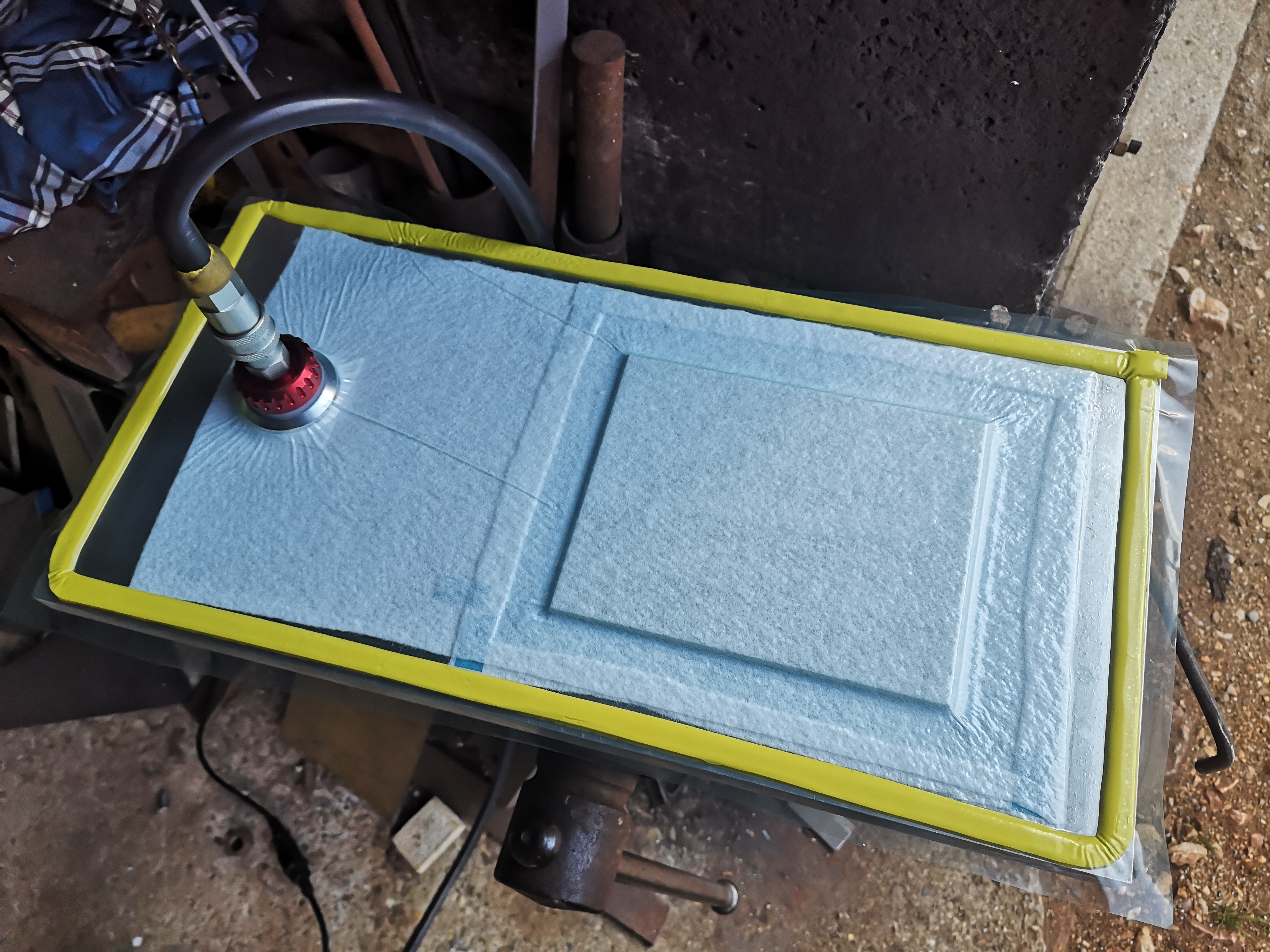
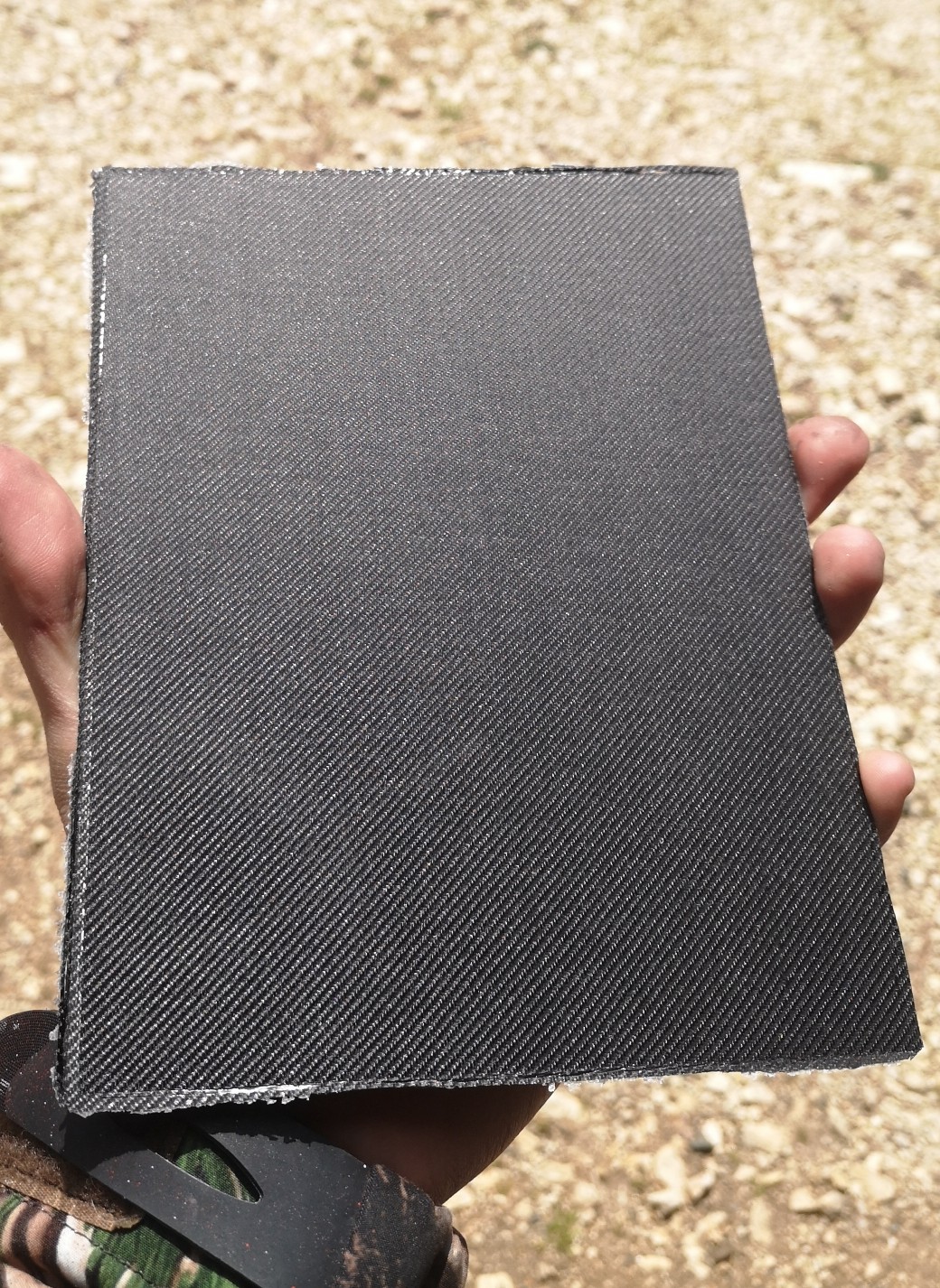
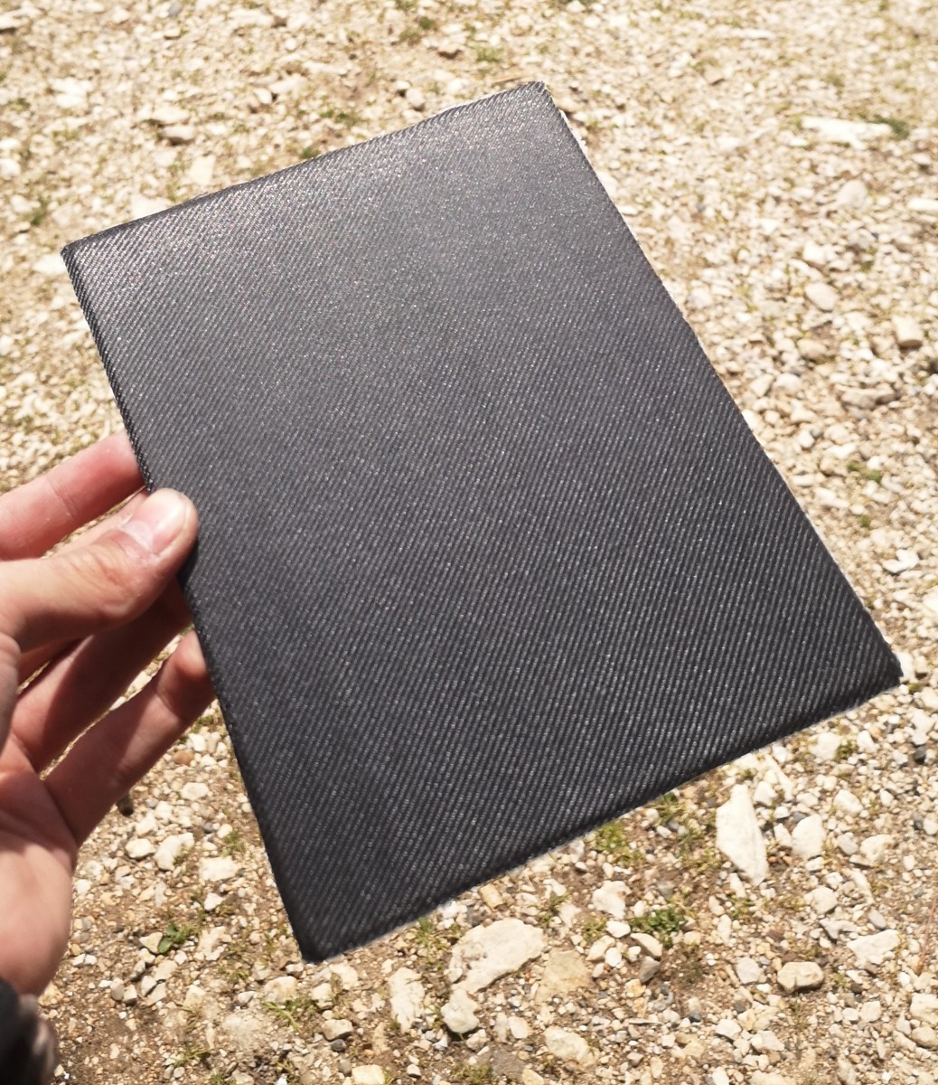
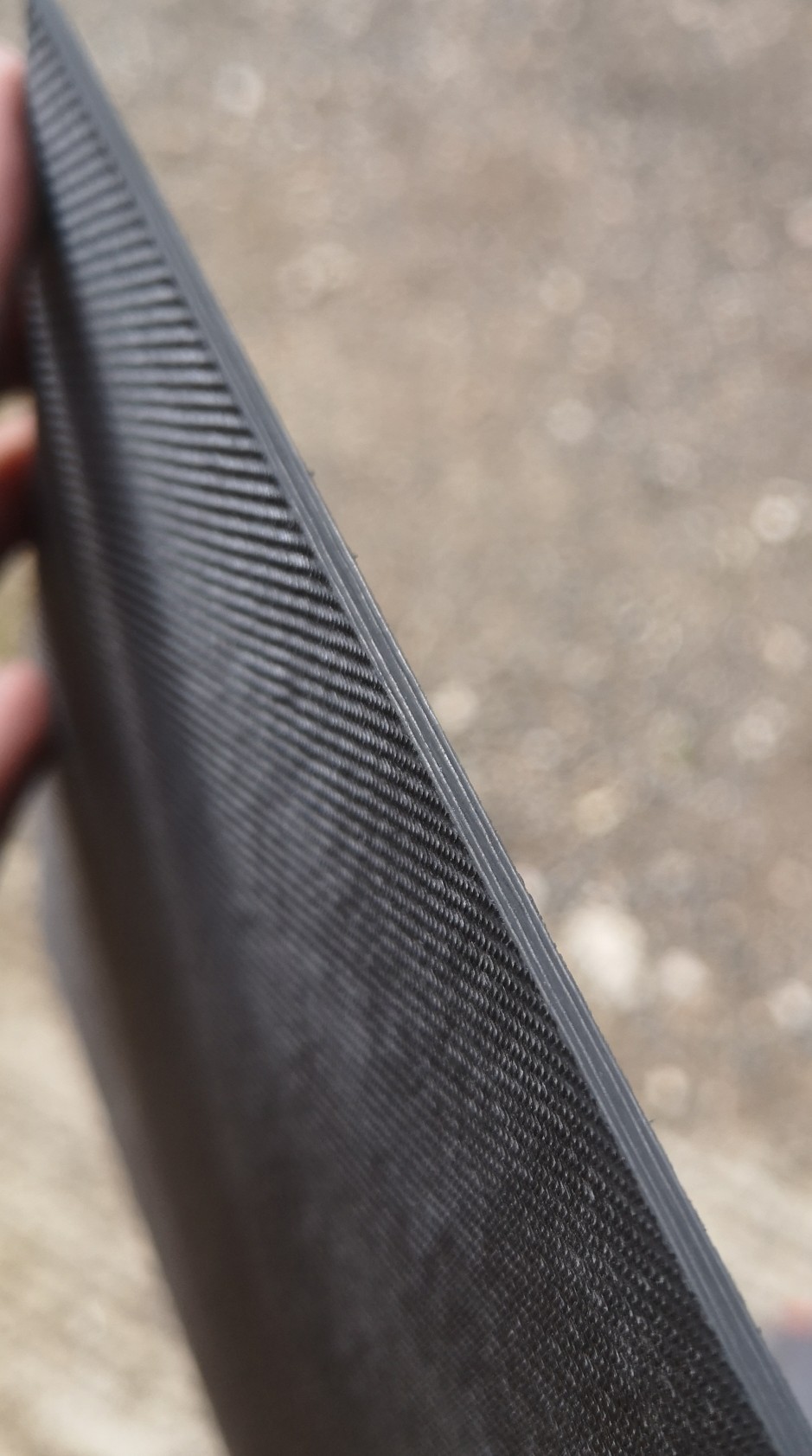
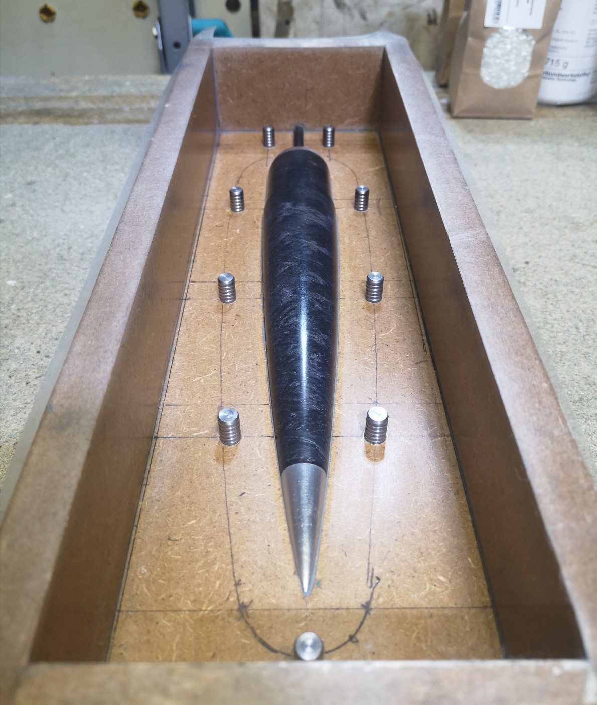
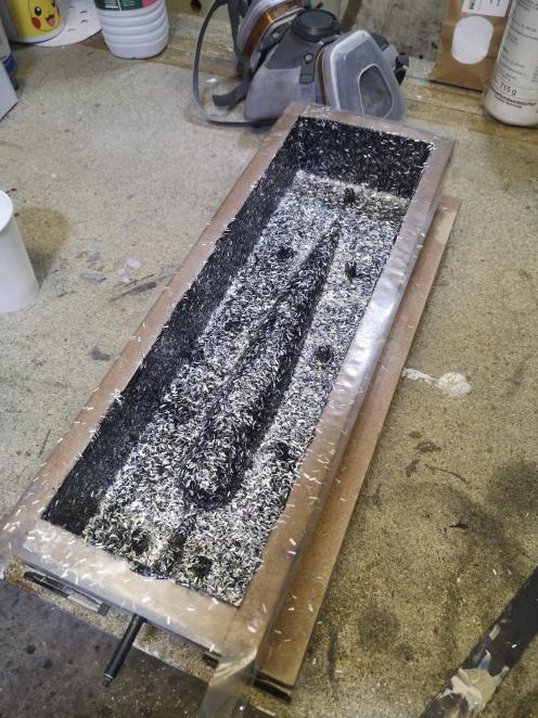
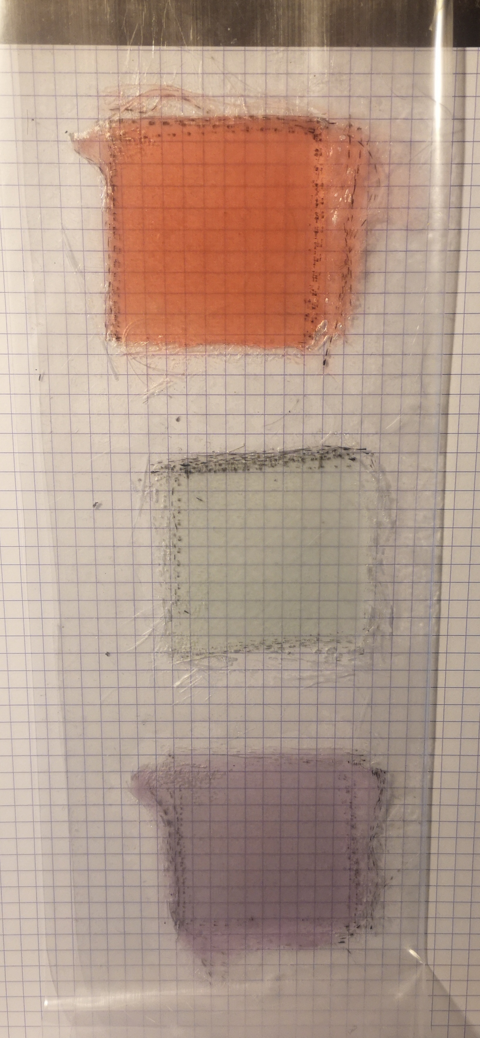
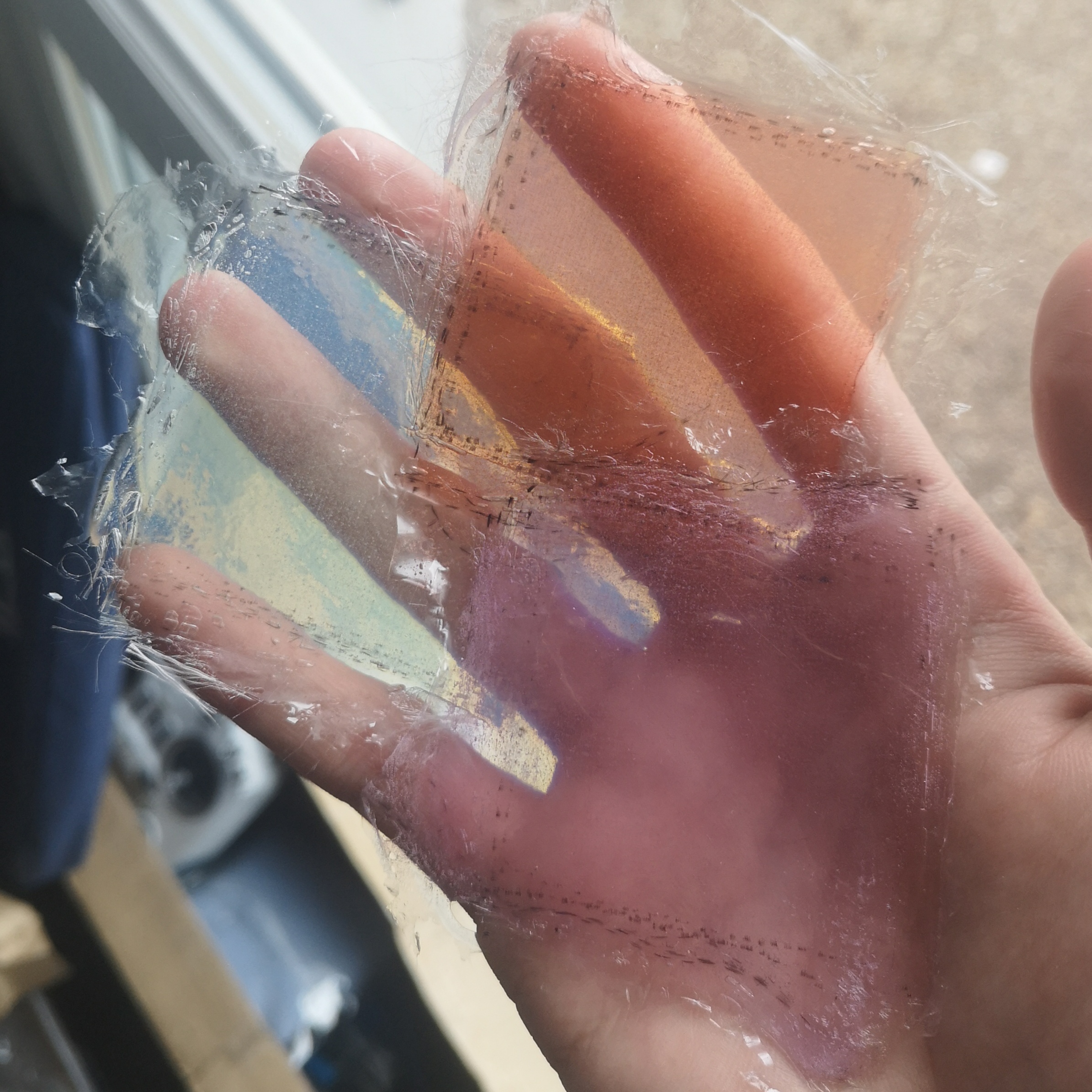
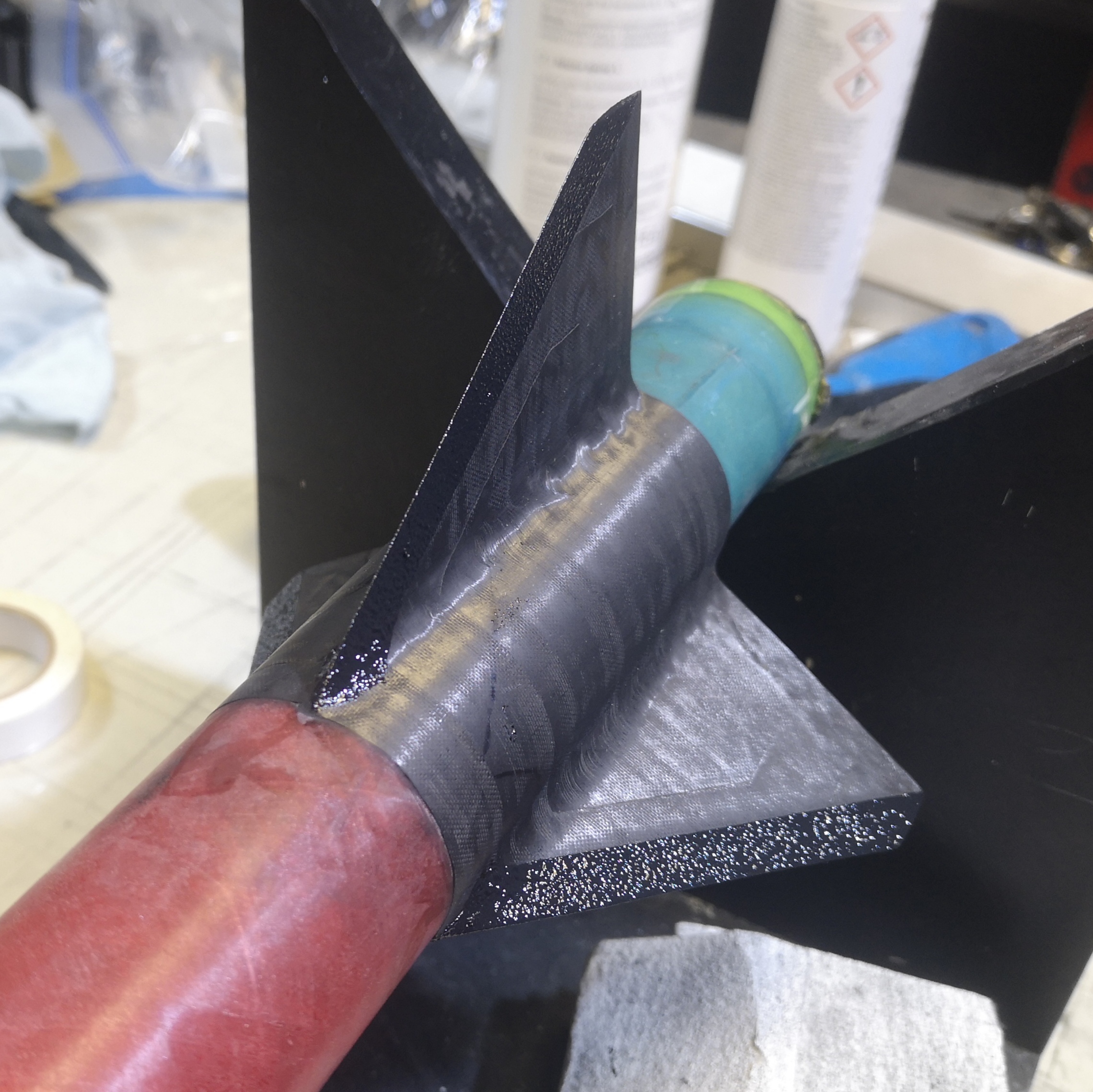
Fins: 2.4mm unidirectional carbon fiber plates, bonded with DP490, tip-to-tip TBD.
Electronics: Stratologger CF or AltimaxSimply 2018, tracking using an Eggfinder Mini. I also want to add a small camera such as a Runcam split3 or split4.
Ejection: surgical tubing zip-tied to the bulkhead, this is to prevent the ejection charge from being disabled during the acceleration.
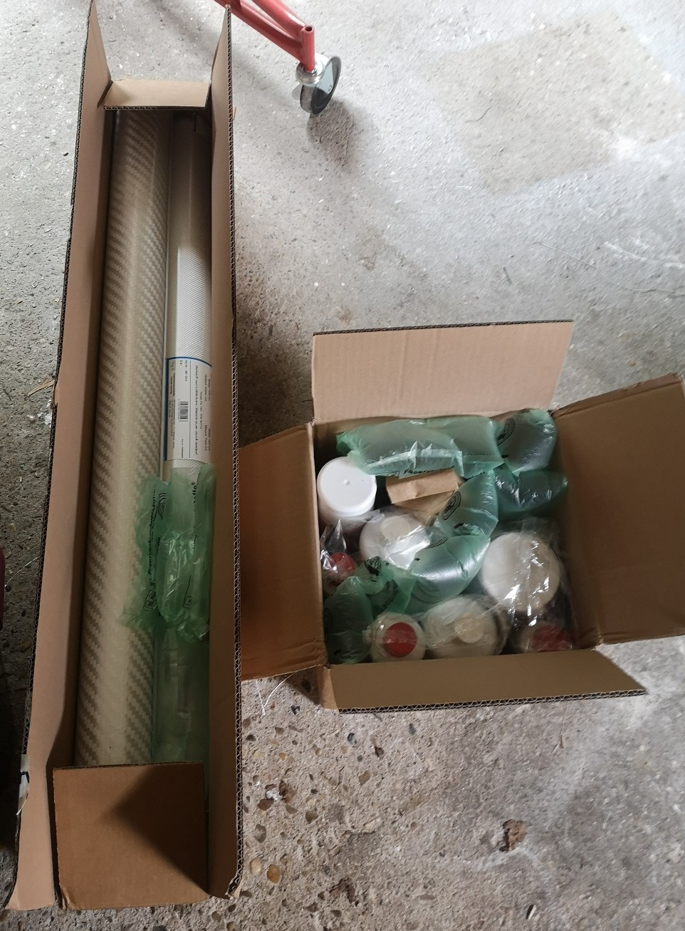
Some of the parts layed down. I need a longer section of coupler :/

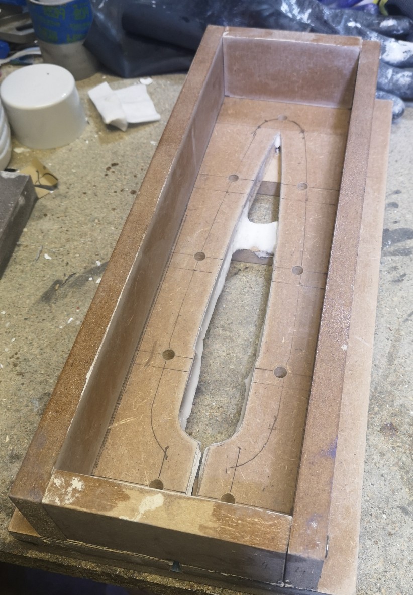
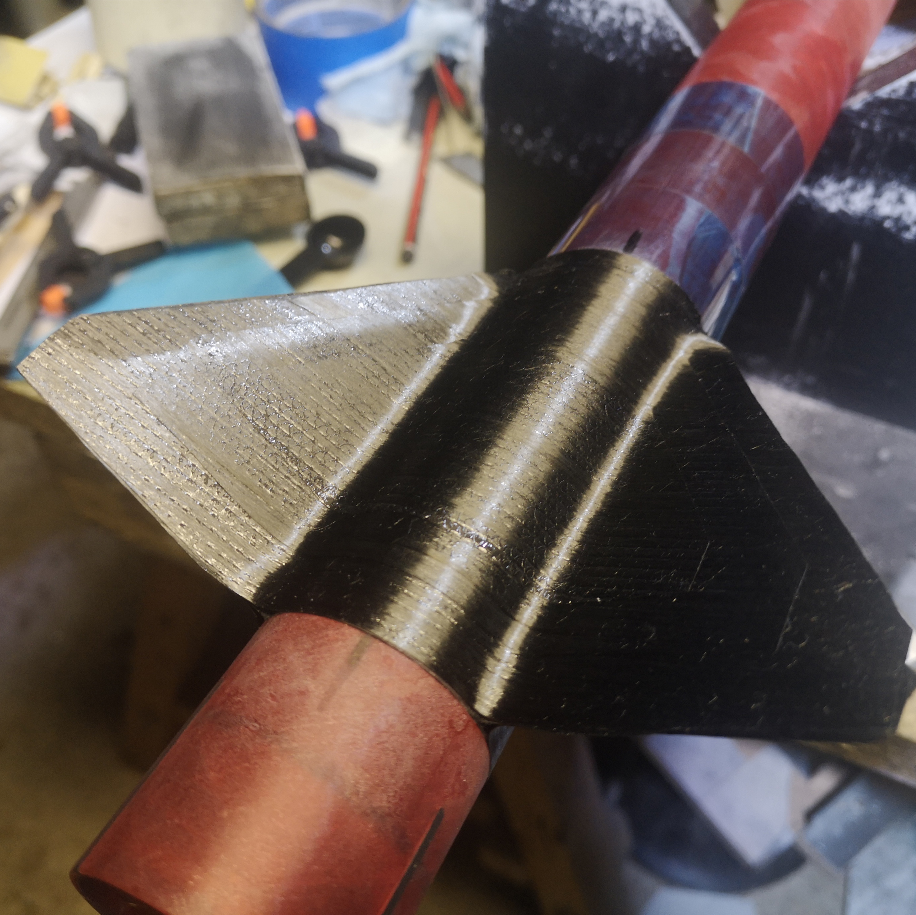
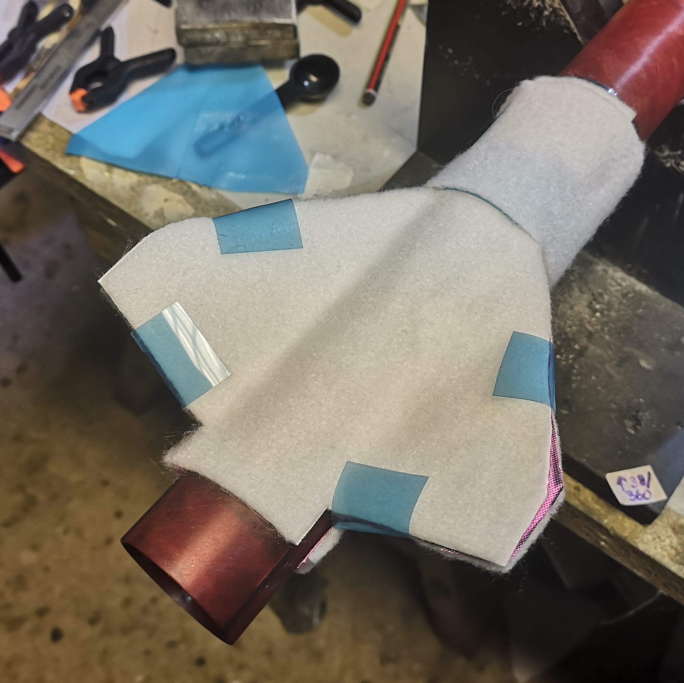
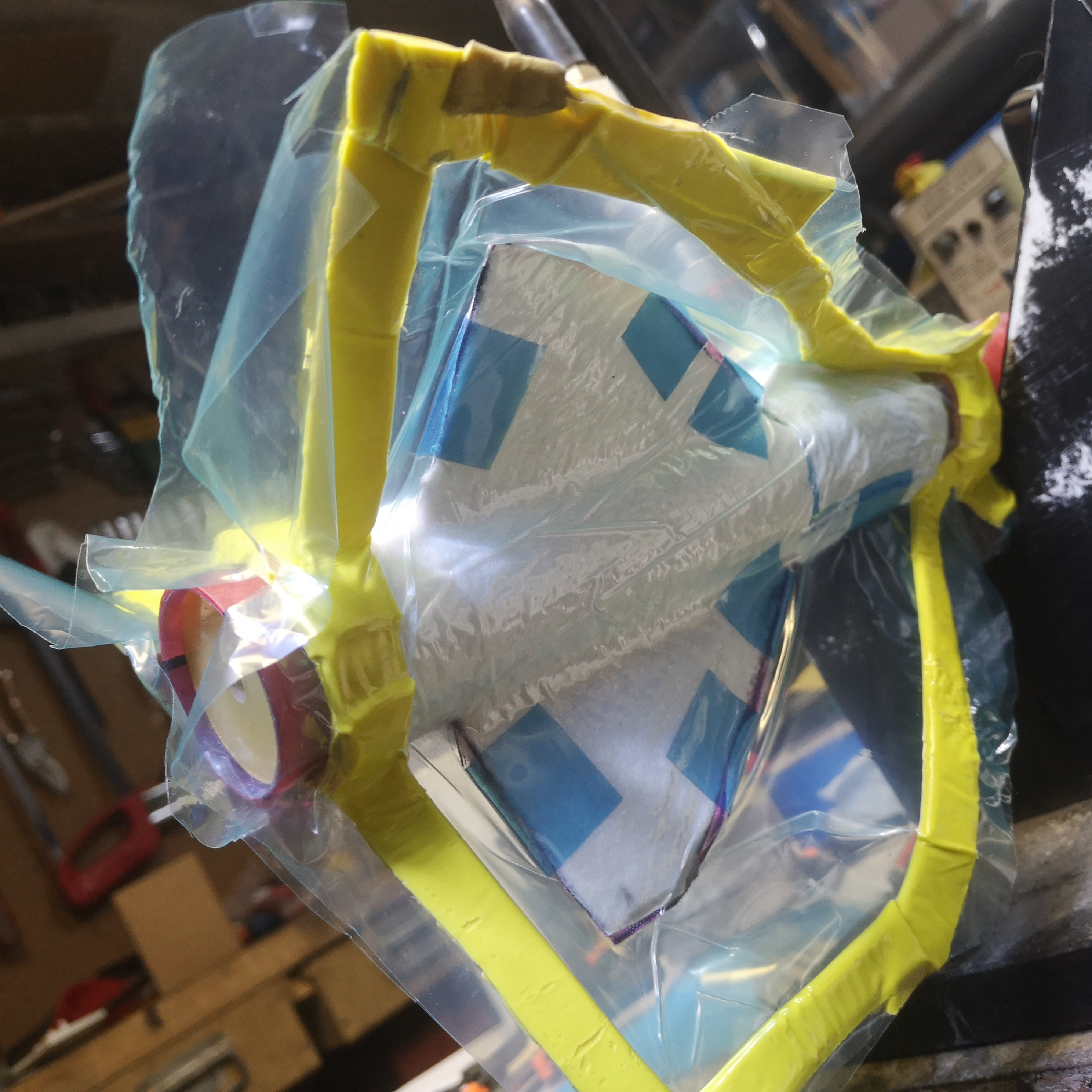
Because I also want to "test" the rocket on smaller 29mm motors. I made an adapter using the centerings rings and MMT provided in the kit:

Still missing the thrust plate.
To be continued.
The goal is to fly it on the H999 and the I1299.
Most of the parts come from a Darkstar Mini I got from https://eurospacetechnology.eu/index.php.
I will be using: the body tube with the slotted section removed, the nosecone, fins as stock to make the bulkheads, shock cord, and parachute.
The part between the end of the casing and the nosecone shoulder will be supported by a piece of fiberglass coupler as a sanity check.
Motor retention: threaded Aerotech closure + bulkhead on the stiffening coupler.
Fins: 2.4mm unidirectional carbon fiber plates, bonded with DP490, tip-to-tip TBD.
Electronics: Stratologger CF or AltimaxSimply 2018, tracking using an Eggfinder Mini. I also want to add a small camera such as a Runcam split3 or split4.
Ejection: surgical tubing zip-tied to the bulkhead, this is to prevent the ejection charge from being disabled during the acceleration.
Some of the parts layed down. I need a longer section of coupler :/
Because I also want to "test" the rocket on smaller 29mm motors. I made an adapter using the centerings rings and MMT provided in the kit:
Still missing the thrust plate.
To be continued.


")


.JPG")
.JPG")

.JPG")