Fin Alignment

The Rocketry Forum

Help Support The Rocketry Forum:

This site may earn a commission from merchant affiliate links, including eBay, Amazon, and others.

Iceman1979

Well-Known Member
Joined
Feb 24, 2009
Messages
110
Reaction score
0
Ok Guys/Gals,

I used AutoCad to make my fin alignment tool. As you can see in the attached document I created a small circle for my MMT and a larger one for my BT. The lines are where the fins would be and are the width of the wood.

I would place the piece of paper on a flat surface and then place the MMT on it's circle and then mark the spots for the fins. using a ruler and a piece of angled aluminum (L shaped) I extended the lines down the tube. I repeated this step for the BT as well.

I'm curious how others have done it. Anyone care to share some examples. I like having options and maybe there is a better/easier way out there.

View attachment Fin Placement-Model.pdf
 
I'll somtimes wrap a piece of paper around the body tube and mark it where it overlaps. That gives me the circumference. I'll then draw that width in Corel Draw and simply divide that width in equal segments according to the number of fins I have.
 
I'll somtimes wrap a piece of paper around the body tube and mark it where it overlaps. That gives me the circumference. I'll then draw that width in Corel Draw and simply divide that width in equal segments according to the number of fins I have.
I do something similar but without using a computer.

I wrap a piece of paper around the body tube and mark it where it overlaps. Then I take the paper off and fold it into as many sections as there are fins. I mark the paper on each fold and then wrap it around the body tube again, but tape it to itself this time.

Then I mark the body tube at each mark on the paper, then I rotate the wrap around the body tube to check the alignment of the marks on the body tube. If any of them are off, I adjust them as needed.

Then I do the usual "extend the marks down the body tube" thing.
 
A wile back i tried grooving my centering rings the width of the fin tabs to make the fins "self-aligning".
Its actually quite easy, and makes assembly stronger and idiot-proof, an important benefit in my case ;-)
it just takes a minute to improvise a ring grooving jig for the table saw from wood scraps. if using home made wood rings, its even easier, if you groove them as a bulkplate before cutting out the center hole.
i've been doing that ever since, unless doing a min-diameter model, its the way to go for me.
Yes this applies mostly to mid and high power models with wood or composite rings.
For low power stuff, i print some guides like have been posted here, but i laminate that to thick corrugated cardboard and cut out the fins and body tube to to make a "slide-on" fin holder
 
Last edited:
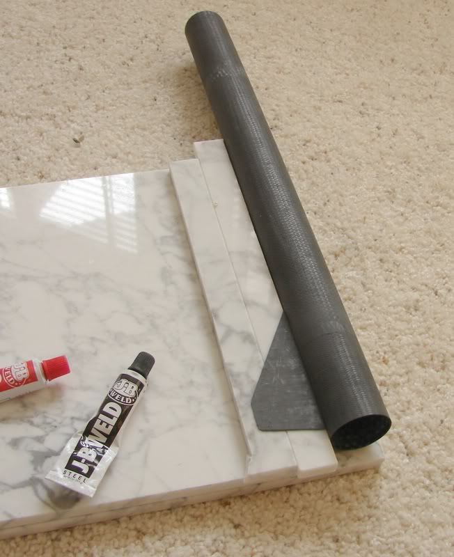
Here's what I did last week:
DSC00096cropped.jpg


Hopefully this is self-explanatory.
The floor tiles are cheap and useful for all kinds of things, including providing a very flat surface for laying up the fin stock.
 
For 3" and 4" rockets, I've used the template approach (I used powerpoint) with the template transferred to foam board. This has worked very well in combination with a "door frame" parallel line on the rocket.

I did a smaller rocket recently (29 mm), and I had a heck of a time getting the fins on straight. I initially tried the "marble tile" approach, except I used wood. I found it hard to get the "shelf" height at exactly the right level, and while this should have worked, it did not turn out well.

I ended up making a simple jig out of two pieces of balsa. The pic below sort of illustrates the approach, although more was involved in the execution. Once it was set up though, the fins went on fast, and it flew very straight.

Jim

Alignment.JPG
 
Jim,

Looks good. I'd like to know more about the setup if you have the time and want to elaborate on it a bit more.

I've seen where a guy took a square sheet of wood and cut a hole in the center and then routed out the spot for the fins. When it was done he could slide that over the end of the rocket and it would hold the fin in place while it was drying.

I think some sort of jig is needed for sure to make sure the fins are alligned correctly. I think I'll look into making some sort of jig for my rocket.

For my Wife's rocket I drew the lines on the CR and the MMT and eyeballed it. I guess it was a good eyeball becuase when she slotted the tube according to the lines and the fins slid right in without any binding.

Thanks
John
 
Here's what I did last week:
DSC00096cropped.jpg


Hopefully this is self-explanatory.
The floor tiles are cheap and useful for all kinds of things, including providing a very flat surface for laying up the fin stock.
It is self-explanatory, but how did you get exactly the right thickness on the tiles?
 
The template is the way to go. Of course, with surface mount, you still have to make sure the fin stays on your line till set.

For a position wrapper I use Gary Crowell's VCT program (or under the tool tab in VCP). Up to 8 fins and you can cant them if you like.

For alignment, again in VCT I print out the template, glue it to foamboard or heavy poster board (or directly onto cardstock for small rockets), then cut it out.

IMG_1005.JPG
 
For marking tubes for fin attachment i've been using these marking guides for a very long time.

For fin attachments several methods, one being an old estes fin jig. that I've altered a good bit to allow use with other LPR body sizes.

or a plate glass alignment method similar to AdrianA's, using different thicknesses of Plate glass, Marble tooling borads & precision blocks.

Estes Fin Alignment Jig-h-sm_7 pic Pg_11-05-06.jpg
 
Last edited:
Jim,

Looks good. I'd like to know more about the setup if you have the time and want to elaborate on it a bit more.


Sure. The longer pieces were something like 1" x 20" x 1/4" balsa. I just verified that they were straight. Then, I put some fin stock pieces at two spots to hold them apart at the right spacing. Obviously, it is easy to look along the length of the tube to see that the wood pieces are exactly aligned with the body tube, and that is evident in the picture.

The cross-wise wood pieces were there to allow me to support the jig on top of the body. They also allowed me to change the angle of the fin relative to the body tube so that I could get the fin exactly perpendicular to the body tube.

This was easy to use once I got it set up. The thing I liked was being able to visually verify that things were aligned.

Jim
 
I do something similar but without using a computer.

I wrap a piece of paper around the body tube and mark it where it overlaps. Then I take the paper off and fold it into as many sections as there are fins. I mark the paper on each fold and then wrap it around the body tube again, but tape it to itself this time.

Then I mark the body tube at each mark on the paper, then I rotate the wrap around the body tube to check the alignment of the marks on the body tube. If any of them are off, I adjust them as needed.

Then I do the usual "extend the marks down the body tube" thing.

I'll go you one better...

Wrap the paper around the tube onto itself and mark it where it overlaps. Be sure you mark the starting edge with an arrow or something so you measure the right way (I usually just grab a sheet of printer paper to do this) and then measure the circumference between pencil marks. Divide by the number of fins and then mark the edge of the paper where the fins will go.

Now there is an easier way I learned in drafting to divide this up without grabbing the calculator and ending up with a bunch of fractions/decimals and going blind trying to mark the paper at exactly 1 11/32 inch or whatever the fin spacing happens to be... say the tube is 5 13/16 inches in diameter, take your ruler, angle it across the paper from the overlap mark to the right angle edge, and push the ruler UP THE EDGE until the 6" mark is on the edge of the paper, like you were going to draw a triangle with a 6" long hypotenuse line. For a three fin rocket, mark the 2 and 4 inch marks. For a four fin rocket, mark 1.5 inches, 3 inches, and 4.5 inches. Remember the starting point is at the overlap mark and the 6 inch mark is on the edge of the paper above the start mark. Now use a right triangle or square and extend the fin marks down to the edge of the paper to mark the tube. You can use whatever number is greater than the length of the circumference and easily divisible by the number of fins you want on the rocket. The closer the number is to the actual circumference, the better this method works, of course, and you have to transfer them to the papers edge SQUARELY, but most folks have a small square lying around, or can use the square edge of a balsa sheet or another sheet of paper for a square.

Works every time... :) OL JR :)
 
Last edited:
It is self-explanatory, but how did you get exactly the right thickness on the tiles?

JRThro, Since Adrian didn't come back and answer, may I offer mine?

I build almost 100% low-power stuff, so a "big" ceramic floor tile is big enough for my work. To adjust the step size (distance from bottom of BT to lower face of fin) I slip some squares of cardboard underneath the tile, like tablet backing cardboard, or really anything of nice uniform thickness. To make fine tuning adjustments to the step size, I slip some sheets of paper under the tile. Printer paper is around 0.0040 inches per sheet thick (500 sheets in a 2.0 inch-thick ream of 20 lb paper).
 
The template is the way to go. Of course, with surface mount, you still have to make sure the fin stays on your line till set.

For a position wrapper I use Gary Crowell's VCT program (or under the tool tab in VCP). Up to 8 fins and you can cant them if you like.

For alignment, again in VCT I print out the template, glue it to foamboard or heavy poster board (or directly onto cardstock for small rockets), then cut it out.

I so like this approach personnally, I have plenty of foam board laying around...I'll use this on my next 4 builds during our Hot/Humid months coming up.
 
Back
Top