


Would some of you mind posting pics of your DD setups? Just got Mach1 3" Black Hole EXT. It will be my 1st DD and I'd like to get some ideas on how to do it. Thanks much.
You are using an out of date browser. It may not display this or other websites correctly.
You should upgrade or use an alternative browser.
You should upgrade or use an alternative browser.
Dual Deploy
- Thread starter David Schwantz
- Start date
Help Support The Rocketry Forum:
This site may earn a commission from merchant affiliate
links, including eBay, Amazon, and others.
Anything is of help. chute attachment, motor attachment, shock cord and chute layout. I ordered the Black Hole from Mach1, and got the ext kit, so I am looking at making it so that I can fly both motor eject on just the short tube and then being able to add the ebay and the longer tube to fly DD. Making a sled is no problem, but looking for ideas on how to attach everything and still make it easy to switch over. It does have an AV bay in the NC also. Just made a bulk head for a shock cord mounting hdw, I do not like the idea of tying it to the motor mount as how can you replace it if needed?
Would some of you mind posting pics of your DD setups? It will be my 1st DD and I'd like to get some ideas on how to do it. Thanks much.
I second the motion. Pics of av bay setups, parts descriptions, building steps, electronics used, etc. Any and all info would be appreciated.
Hey Solid, this will be my first DD.
What about you? What kit are you going to use?
What about you? What kit are you going to use?
Binder Design sells just about everything you need for wiring an AV bay.
https://binderdesign.com/store/page23.html
Crazy Jim (blackjack) has a good tutorial here too:
https://www.rocketryforum.com/threads/how-to-build-a-stock-3in-darkstar-cj-step-by-step.55019/
https://binderdesign.com/store/page23.html
Crazy Jim (blackjack) has a good tutorial here too:
https://www.rocketryforum.com/threads/how-to-build-a-stock-3in-darkstar-cj-step-by-step.55019/

This will also be my first (non Jolly Logic chute release) dual deploy. My plan is to use the LOC 3” Iris although we will see what shakes out after all the Black Friday sales. I’m still in the planning stages. Hoping for an April 2019 attempt at Red Glare.
Here is the altimeter bay for my Wildman Darkstar 2.6. It has an Eggtimer TRS and Altus Metrum EasyMini wired up to 3 lipos (1 for the easy mini and 2 for the TRS). Main power for both is controlled by mag switches and there is a pin headphone jack setup for the TRS deployment charge power. Charge wells are cut down 30-06 cases.
Attachments

KenRico
'Just the Tip'
- Joined
- May 31, 2011
- Messages
- 2,744
- Reaction score
- 56
Agree with the BatMite BinderDesign/Doghouse charge wells and standard terminal blocks are inexpensive and work great .4" MAC Performance kit. MW RRC2+, StratologgerCF. Wiring kit and wells from Doghouse, aka Binder Design. Forged steel eyebolts from Granger.
View attachment 367224
I pull the stainless eyebolts from Wildman and have used aluminum 1/4-20 from Grainger . I like the stepped fiberglass lids for fg and paper rockets av bays but toss the paper coupler and replace with a blue tube one.
Besides 'keying' the wiring so that wiring cant be reversed, it helps me to double nut or nylon nut the bottom of the all thread to the lower lid and then use stainless wingnuts on top . These things eliminated the oops, main popped at apogee for me.. Also it allows me to pull it all apart and put it back together quickly.
Wayco showed me how to cover the terminal blocks with green body shop masking tape to minimize any scorching
Kenny
4" MadCow bay, RRC3, StratoLoggerCF. Dual pull-pin switch from Lab Rat rocketry, modular wiring and battery holders from Dog House rocketry. Charge wells from Schedule 80 CPVC with 4 ml centrifuge tubes to hold BP plus ematch (https://www.rocketryforum.com/threads/dual-deployment-charge-cups.49878/). Firewire ematch from csrocketry.
Couldn't figure how to lay out everything on the standard sled (lesson: leave the battery brace piece off the sled), so got an extra sled and mounted them back-to-back. See pics below.
Bill


Couldn't figure how to lay out everything on the standard sled (lesson: leave the battery brace piece off the sled), so got an extra sled and mounted them back-to-back. See pics below.
Bill
Zeus-cat
Well-Known Member
- Joined
- Mar 14, 2009
- Messages
- 4,991
- Reaction score
- 1,455
4" MAC Performance kit. MW RRC2+, StratologgerCF. Wiring kit and wells from Doghouse, aka Binder Design. Forged steel eyebolts from Granger.
View attachment 367224
If room allows I would mount the battery on the opposite side from the altimeter. I have seen batteries come loose in flight and the damage they can do to electronics is incredible. When using two like pictured, I would, if possible, mount one altimeter and its battery on one side and the second altimeter and battery on the other side. regardless of setup you really want to secure your batteries. I've seen people use just tape and trust me, it ain't enough.
Since then I have started tying them down with zip ties. I also orient them with the leads facing down when the rocket is vertical.If room allows I would mount the battery on the opposite side from the altimeter. I have seen batteries come loose in flight and the damage they can do to electronics is incredible. When using two like pictured, I would, if possible, mount one altimeter and its battery on one side and the second altimeter and battery on the other side. regardless of setup you really want to secure your batteries. I've seen people use just tape and trust me, it ain't enough.
Nathan
☢
- Joined
- Apr 19, 2012
- Messages
- 2,230
- Reaction score
- 755
Here are some pics of the Madcow 4" av-bay from my first dual deploy rocket about 5 years ago. I wouldn't recommend painting your av-bay coupler like this because the paint makes it a tight fit in the airframe tube. And also it is better to use welded eyebolts that the open eyebolts that I used. The av-bay is attached to the payload tube by the 3 bolts that screw into nuts which are fixed to the inside of the av-bay coupler tube with epoxy putty. This av-bay did not have a switch band and instead used a switch accessible through the vent hole. I never did that again because it is a PITA to get the switch perfectly lined up below the vent hole. Be sure to use only stainless steel metal hardware because otherwise it will get rusty from the very corrosive black powder residue.
Last edited:
snrkl
Well-Known Member
- Joined
- Apr 11, 2017
- Messages
- 1,368
- Reaction score
- 210
My first DD eBay build is in my build thread. Starts on post #94
https://www.rocketryforum.com/threads/new-102mm-project-chimichunga-i.145203/page-4
https://www.rocketryforum.com/threads/new-102mm-project-chimichunga-i.145203/page-4
https://www.rocketryforum.com/threads/madcow-super-dx3-cardboard-and-plywood-kit-38mm-mmt.147205/
Madcow super dx3 my first DD rocket and what I used for my L2.
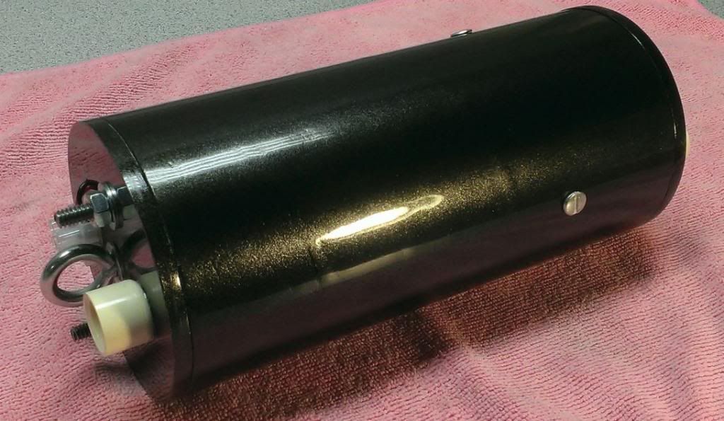
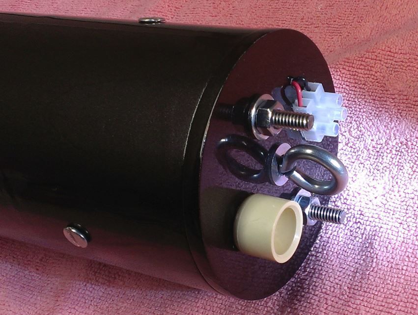
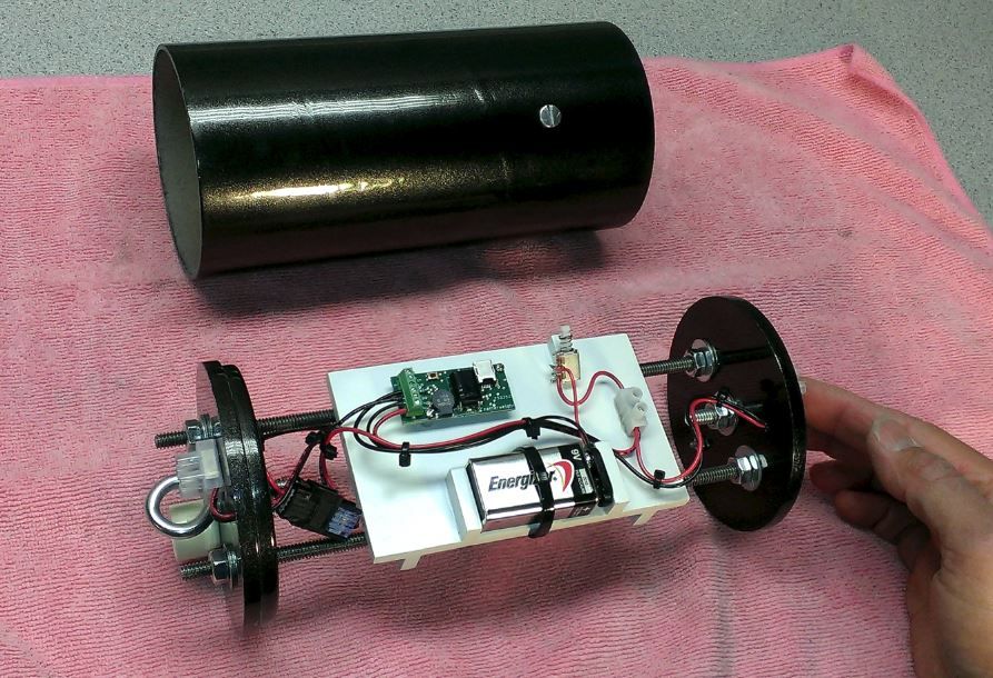
Here is a few more detailed pics of the eBay layout. RRC2+, RRC3, micro peak altimeter, JL3, dual 7.4v lipo battery's and dual rotary switches. Charge Wells are 1/2" pvc caps with terminal blocks for the ematches, aluminum all thread rod, welded eye bolts for shock cord attachment.
I also have marks on the lids, coupler and airframe to get every thing lined up and drogue/main events marked and what charge well goes to what altimeter.
~John
Madcow super dx3 my first DD rocket and what I used for my L2.
Here is a few more detailed pics of the eBay layout. RRC2+, RRC3, micro peak altimeter, JL3, dual 7.4v lipo battery's and dual rotary switches. Charge Wells are 1/2" pvc caps with terminal blocks for the ematches, aluminum all thread rod, welded eye bolts for shock cord attachment.
I also have marks on the lids, coupler and airframe to get every thing lined up and drogue/main events marked and what charge well goes to what altimeter.
~John
Attachments


DAllen
Well-Known Member
There are oodles and oodles of threads out there that have ebay pictures. Here's one I did a while back:
https://www.rocketryforum.com/threads/4-solar-warrior-upscale.54744/
I don't build things...traditionally lol.
https://www.rocketryforum.com/threads/4-solar-warrior-upscale.54744/
I don't build things...traditionally lol.
I have seere people are having a switch band??? What is that? I have seen others have a push button switch, do you access it from outside the tube on the launch rail just before launch? Thanks.
The switch band is a small ring of body tube glued to the coupler that makes up the eBay.
This is where you will have a series of vent holes to have accurate atmospheric changes for the altimeters to record, and at least one hole to gain access to a safe and easy way to arm the electronics for the rocket, only for pre flight checks and for real on the high power pad before the rocket is vertical, or the ignitor goes in the motor at least.
I have twin rotor rotory switches in my MC SDX3 but push buttons, switches, pull pins, magnetic switches, twist and tape of 2 wires, all have there ups and downs and comes down to what you are comfortable with using.
~John
The switch band is visible in my picture in post #7 above. When that shot was taken, it had not yet been drilled for vent holes. Some people call a switch band a vent band; same thing. Not everyone mounts the switch on the outside.
In my picture, the two rotary switches at the bottom of the pic would later be mounted to the switch band via 1/2" holes and tightened at the back.
My first DD rocket had no switch band. My switch was mounted directly to the airframe. I had to lower the upper bulkhead down into the payload tube with the harness, then connect the aft wiring, then slide in the sled, then attach the aft bulkhead. Just another way of doing it, but I'd rather have a completely removable AV bay.
Following on the post above:
- Push button - stick out and cause drag
- Toggle switches - stick out and cause drag, and can get flipped mid-flight (VERY BAD) in some cases
- Pull pins - very effective, but can be time consuming "finding the hole"
- Magnetic switches - can be time consuming waving the magnet, trying to find the switch, no visual confirmation
- Twist and tape - looks ugly, make sure tape does not blow off
- Twist and tuck - make sure tucked ends do not short against a ground
- Rotary - plastic ones break easily, metal ones stick out, but not as far as toggle and push-button
- Metal rotary with key - my preferred, although no one else can disarm my electronics without the key
woferry
Well-Known Member
Magnetic switches - can be time consuming waving the magnet, trying to find the switch, no visual confirmation
Just a comment on this one, this is pretty easy to solve, just line-up the Mag Switch with one of the vent holes. I do this on every AV Bay I've made (whether by hand or 3D-printed). So the vent hole both makes it easy to find where to swipe the magnet, and since it's lined-up with LED on the board there's a clear visual indication as well. Since I typically make 3 vent holes, if I have redundant electronics or the like then I'll line up switches with two of the holes.
You also left out the Eggtimer WiFi Switch, where you can activate/deactivate your electronics via any WiFi-capable device (phone, tablet, laptop, etc). It does burn a good bit of power all the time, so you need a decent size battery which means it's not a good solution for preparing your electronics well ahead of a launch, but it works great for the relatively short period moving from your camp to the launch pad. Similarly, if you use the Eggtimer Quantum (or the new Proton) the WiFi switch is built-in, so you don't need any other switches unless you want an option to seal-up the AV Bay well ahead of time.
- Joined
- Jan 11, 2013
- Messages
- 6,450
- Reaction score
- 961
You have to scroll down to see these pics..
This is a bullit proof av bay set up in a 3" airframe..
2 full size altimeters, 2 batteries, 2 electronic switches..
Completely redundant..
https://onebadhawk.com/stainless-steel-u--bolts.html
The pics the furthest down are on the nosecone bay for tracking..
One ham based beacon and one GPS based tracker..
Each with it's own battery and antenna set up..
Teddy
Teddy, the little red JST connectors, are they for the ematch? How do you secure them in the charge cannisters and do they come with matching connecters? Do you carry them for sale? Thanks, Dave
- Joined
- Jan 11, 2013
- Messages
- 6,450
- Reaction score
- 961
Teddy, the little red JST connectors, are they for the ematch? How do you secure them in the charge cannisters and do they come with matching connecters? Do you carry them for sale? Thanks, Dave
Dave,, on one side of the av bay the bulkhead is a solid part of the assembly..
On the other side there is no bulkhead..
This is how you assemble the av bay, first you slide the no bulkhead side into the coupler, then you cap the coupler with the other bulkhead assembly.. The other bulkhead assembly has 2 charge wells, so it has 2 pairs or wire on it's bottom with the 2 matching JST plugs. You'll notice one is female and one is male, so they can not be connected wrong,, primary must be primary and secondary must be secondary.. There is no other way it will go together.. So the 2 pair of JST on the no bulkhead side is to make the bulkhead removable, they are for the primary and secondary deployment charges..
On the other side of the av bay you'll notice a single pair of wire and a JST connector..
Inside the booster is a thin brass tube that runs down through the lowest centering ring..
This connector and wire is to do the air-starts..
This rocket ( Europa Express ) is a 54mm central and 2-- 38mm outboard motor mounts..
In this pic gallery is a nice set of stills of Europa doing an air-start..
https://onebadhawk.com/metra-812015.html
Teddy
My L3 documentation has a detailed build of the bay and the calculations needed.
https://drive.google.com/open?id=1i4anunZXsiG7dyIP78nmFN7WJrSK-7uAgVvensHU9ok
https://drive.google.com/open?id=1i4anunZXsiG7dyIP78nmFN7WJrSK-7uAgVvensHU9ok
Nathan
☢
- Joined
- Apr 19, 2012
- Messages
- 2,230
- Reaction score
- 755
Here's the 38mm av bay that I just built for my 1.6" Madcow DX3. It has a RRC2+ altimeter and a screw switch, both from Missileworks. The charge canisters are made from aluminum tubing. Welded eye bolts are from OneBadHawk. No room for terminal blocks so I will be connecting the e-matches directly to the altimeter. The plan was to access the screw switch through the vent hole but the screw fits so close to the hole that I think I'm going to need another vent hole.
Here a couple of pics of what I have so far. Forged SS eye bolts, 10-24 rods, charge wells are .44mag casings, gonna load 31.9 grains of Hodgen H110 ")
But my question is the fit of the AV Bay to the tubes is very loose. I have about 1/2" of play at the top of the payload section. Is this correct? I was thinking that the fit should be tighter.
But my question is the fit of the AV Bay to the tubes is very loose. I have about 1/2" of play at the top of the payload section. Is this correct? I was thinking that the fit should be tighter.
Attachments


Nathan
☢
- Joined
- Apr 19, 2012
- Messages
- 2,230
- Reaction score
- 755
Here a couple of pics of what I have so far. Forged SS eye bolts, 10-24 rods, charge wells are .44mag casings, gonna load 31.9 grains of Hodgen H110
But my question is the fit of the AV Bay to the tubes is very loose. I have about 1/2" of play at the top of the payload section. Is this correct? I was thinking that the fit should be tighter.
No it should not be that loose. I had a similar problem with my 8" diameter Frenzy XXL; the av bay coupler tube was a little too small. My solution was to buy a new coupler tube which fixed the problem.
rharshberger
Well-Known Member
These are the bays from my Rabid Weasel (Blue Tube Weasel) and 1.6" Frenzy XL (fiberglass). The Rabid Weasels bay is from SMT Designs.
Frenzy XL 1.6" Fiberglass Bay

Rabid Weasel Bay by SMT Designs, SMT also made a Nose cone tracker bay for the rocket as well.


Frenzy XL 1.6" Fiberglass Bay
Rabid Weasel Bay by SMT Designs, SMT also made a Nose cone tracker bay for the rocket as well.
Similar threads
- Replies
- 41
- Views
- 1K
- Replies
- 6
- Views
- 356