


luke strawwalker
Well-Known Member
- Joined
- Jan 18, 2009
- Messages
- 9,147
- Reaction score
- 40
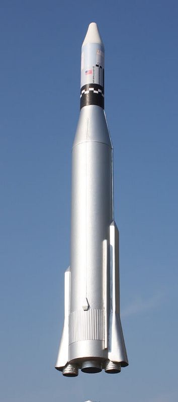
Started my next build last night-- the Dr. Zooch Atlas-Agena. This is a pretty cool looking BT-60 based kit with a BT-50 serving duty as the Agena upperstage. The kit consists of said tubes, along with a BT-20 motor mount tube and associated hardware, a BT-5 "engine spoof" tube for the outboard engines of the Atlas booster (and also serve to hold the flame fins for stability in flight), three centering rings, a balsa transition for the conical upper section of the Atlas to which the Agena is mated, and a balsa nosecone for the Agena, parachute, balsa sheet, the usual signature Dr. Zooch smart-aleck instructions, and a wrap/pattern sheet for the Agena wrap, flame fin pattern, centering ring cutout patterns, side-pod patterns for the Atlas booster engines, and various other paper stuff.
So, lets get started. The kit starts off with the motor mount. Get two of the three centering rings from the box and the wrap sheet, and with a sharp hobby knife, carefully cut out the two centering ring cutout patterns. Smear a light coat of white glue onto the centering rings, and carefully glue the patterns onto the centering rings, press firmly to set them, and put them aside to dry. Take the BT-5 "engine spoof tube" from the kit (be sure and double-check the lengths as there are SEVERAL short tubes in the kit of differing diameters that are fairly close in size, so make sure you've got the right one) and measure, mark, and cut it in half. Wrap a strip of paper around the spoof tubes and mark a line around the tube 1/2 inch from the rear ends of the tubes. Get the "poly coated popeilium" shroud line material from the box and cut two nine inch sections off it, and using a dab of yellow glue, glue them onto the rear end of the engine spoof tubes just below the line. Set aside to dry. Once dry, smear some wood glue around the end of the engine spoof tubes, and carefully wind the string around them to make the engine 'hatbands'. Straighten up any misalignments of the strings, and smear a little more glue over them, and set aside to dry. I found that clamping the end of the string down with a hemostat clamp REALLY helps them stay put during drying. Cut the half-moon sections out of the sides of both the centering rings per the instructions, and carefully trim any overhang of the glued-on pattern to the exact outside and inside diameters of the centering rings so they don't interfere with the rings going over the motor mount tube or into the main body tube. Take the main motor mount tube and using a brass angle (or door frame) put a pencil line down the side of the motor tube. I also wrapped a strip of paper around the motor tube, marked it, measured it to get the circumference, and halved that to put another DOTTED line on the exact opposite side of the tube, to help align the motor clip later on when it's installed. (That step isn't in the instructions but it helps me anyway). I also wrapped the strip of paper around the motor mount tube and marked a ring around the tube at 1/4 inch and 1 1/4 inch to help get the centering rings squared up properly to the motor tube. Install the two centering rings and CAREFULLY align the index marks on BOTH of them to the line previously marked on the motor mount tube. Make DOUBLE SURE both rings are perfectly aligned with the vertical index line on the motor tube and as square as you can get them (aligned with the rings drawn around the motor tube). Set this aside to dry. Once dry, fillet the rings. Measure and cut the slit for the motor hook per the instructions. Cut the 'reinforcement band' from the wrap sheet, spread a little white glue on the back, and glue the band directly below the hook slit in the motor tube. Glue in the engine block ring above the hook. Glue on the top centering ring near the top of the motor mount tube.
I deviated a little bit from the instructions and went ahead and installed the motor hook and taped it down with electrical tape before gluing on the side booster engine spoof tubes. I figured this would be a lot easier than trying to thread sticky electrical tape between them to hold the engine hook on after they were glued in place. Then, after marking another ring line around the tubes with the handy paper strip to give the proper 9/16 inch overhang of the spoof tubes, I sanded off the glassine to roughen the tube for a good glue bond, then I carefully test fitted them, trimmed any tight spots in the ring cutouts, and carefully glued the spoof tubes to the outsides of the centering rings per the instructions with white glue. This completes the motor mount with the two outboard booster engine 'spoofs' which also hold the flame fins for flight.
Meanwhile, I also went ahead and hardened the balsa nosecone and transition with CA glue, and sanded them down smooth, went over them with a coat of thinned Elmer's wood filler, and sanded them down smooth, and primed them. I also filled the spirals on the main body tube with Elmer's filler, and sanded it down and primed it. They're drying now.
Here's the pics of the motor mount... more to come! OL JR")


So, lets get started. The kit starts off with the motor mount. Get two of the three centering rings from the box and the wrap sheet, and with a sharp hobby knife, carefully cut out the two centering ring cutout patterns. Smear a light coat of white glue onto the centering rings, and carefully glue the patterns onto the centering rings, press firmly to set them, and put them aside to dry. Take the BT-5 "engine spoof tube" from the kit (be sure and double-check the lengths as there are SEVERAL short tubes in the kit of differing diameters that are fairly close in size, so make sure you've got the right one) and measure, mark, and cut it in half. Wrap a strip of paper around the spoof tubes and mark a line around the tube 1/2 inch from the rear ends of the tubes. Get the "poly coated popeilium" shroud line material from the box and cut two nine inch sections off it, and using a dab of yellow glue, glue them onto the rear end of the engine spoof tubes just below the line. Set aside to dry. Once dry, smear some wood glue around the end of the engine spoof tubes, and carefully wind the string around them to make the engine 'hatbands'. Straighten up any misalignments of the strings, and smear a little more glue over them, and set aside to dry. I found that clamping the end of the string down with a hemostat clamp REALLY helps them stay put during drying. Cut the half-moon sections out of the sides of both the centering rings per the instructions, and carefully trim any overhang of the glued-on pattern to the exact outside and inside diameters of the centering rings so they don't interfere with the rings going over the motor mount tube or into the main body tube. Take the main motor mount tube and using a brass angle (or door frame) put a pencil line down the side of the motor tube. I also wrapped a strip of paper around the motor tube, marked it, measured it to get the circumference, and halved that to put another DOTTED line on the exact opposite side of the tube, to help align the motor clip later on when it's installed. (That step isn't in the instructions but it helps me anyway). I also wrapped the strip of paper around the motor mount tube and marked a ring around the tube at 1/4 inch and 1 1/4 inch to help get the centering rings squared up properly to the motor tube. Install the two centering rings and CAREFULLY align the index marks on BOTH of them to the line previously marked on the motor mount tube. Make DOUBLE SURE both rings are perfectly aligned with the vertical index line on the motor tube and as square as you can get them (aligned with the rings drawn around the motor tube). Set this aside to dry. Once dry, fillet the rings. Measure and cut the slit for the motor hook per the instructions. Cut the 'reinforcement band' from the wrap sheet, spread a little white glue on the back, and glue the band directly below the hook slit in the motor tube. Glue in the engine block ring above the hook. Glue on the top centering ring near the top of the motor mount tube.
I deviated a little bit from the instructions and went ahead and installed the motor hook and taped it down with electrical tape before gluing on the side booster engine spoof tubes. I figured this would be a lot easier than trying to thread sticky electrical tape between them to hold the engine hook on after they were glued in place. Then, after marking another ring line around the tubes with the handy paper strip to give the proper 9/16 inch overhang of the spoof tubes, I sanded off the glassine to roughen the tube for a good glue bond, then I carefully test fitted them, trimmed any tight spots in the ring cutouts, and carefully glued the spoof tubes to the outsides of the centering rings per the instructions with white glue. This completes the motor mount with the two outboard booster engine 'spoofs' which also hold the flame fins for flight.
Meanwhile, I also went ahead and hardened the balsa nosecone and transition with CA glue, and sanded them down smooth, went over them with a coat of thinned Elmer's wood filler, and sanded them down smooth, and primed them. I also filled the spirals on the main body tube with Elmer's filler, and sanded it down and primed it. They're drying now.
Here's the pics of the motor mount... more to come! OL JR


_05-30-93.jpg")


