


timothyterpsalot
Well-Known Member
- Joined
- May 29, 2009
- Messages
- 84
- Reaction score
- 0
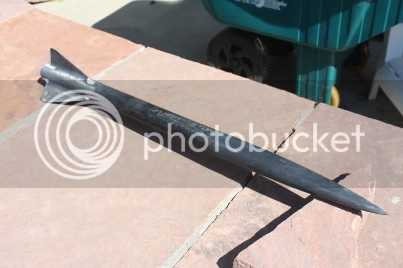
This is a rocket that I have been designing. I am curious to know your thoughts. I want to use it for my Level 2 cert. I eventually plan on flying it with an Aerotech K-250 to just over 15,000 ft. It is made of fiberglass. Fins will be aerofoiled. GPS in the nosecone.
Are there any challenges you would expect me to face with this? Any concerns? I'm just gathering thoughts, many heads are better than one. Thanks!

Are there any challenges you would expect me to face with this? Any concerns? I'm just gathering thoughts, many heads are better than one. Thanks!
 )
) 
 op:
op: