Building the Estes Little Joe II: Tips, Tricks, and Modifications

The Rocketry Forum

Help Support The Rocketry Forum:

This site may earn a commission from merchant affiliate links, including eBay, Amazon, and others.
The Little Joe II off to the side is a 1/70th version that I been building for the last 5 years or more.

Along the same lines, I just found all the parts I have for your 1/70th skins and fins set. I got as far as putting on the BT wrap back in the day. Maybe I can finish that while working on the 1/45th. :)

kj
 
Along the same lines, I just found all the parts I have for your 1/70th skins and fins set. I got as far as putting on the BT wrap back in the day. Maybe I can finish that while working on the 1/45th. :)

kj
lol same here, dug my wraps and fins out, I have an Apogee cone kit so will build in parallel w/ the 1/45th
 
I’ve been working up a decal sheet for the 1/45 model. One reason is for the purpose of having plenty of spares. On my model, I ruined one of the two UNITED STATES sets and had to cut one from a second kit's decal sheet. The other main reason for the sheet is for the General Dynamics / Convair plaques.

The UNITED STATES lettering is a bit wider, because the lettering width is narrowed when applied to the corrugated body. For example, on the real Little Joe-II, the letters were 12” wide as appearing on the body. That’s 0.267” wide at 1/45 scale. The kit decals are about .275” width to begin with, but when applied to the body mine measured out as about .232” wide. So, the corrugations make them narrower by about .043”.

So, to compensate, the lettering needs to be about 18.5% wider than scale to appear the correct width after the decals are applied to the corrugations.

Below is a draft copy. I need to do another conversion to save the UNITED STATES lettering at better resolution.

MIdm21t.jpg


As for the General Dynamics / Convair plaques. Two are shaded gray, for those who may just prefer to do those by printing onto paper, cut out, and stick on (I did that to mine as a temporary measure). For those who want to do the plaques more accurately, the “white” version will print clear on clear decal film, so the clear decal of the plaques can be applied over chrome mylar or some other very smooth metal representing the stainless steel type appearance of the plaques (I’ve done that before, was going to do that eventually with my first one).

I plan to add a long stripe, to the width of the vertical part of the letter “T”, that can be cut up into segments. When I applied the decals on my model, I cut each UNITED STATES decal strip into three pieces. One had the lettering “UNITED STAT”, with the lower 1/8” of the last “T” cut away. That was applied above the STA-227 Splice joint, Then the 1/8” tall “T” was applied to the splice joint. And the remaining “ES” lettering was applied to the corrugation below the splice joint.

So, the long stripe would be an additional source for the 1/8” tall portions, and also as a “patch” source for any localized flaws that were easier to cover over than to remove the decal.

Before I finalize the decal sheet, any suggestions? There’s not much room left, though if there was good reason to add something that needed extra room, I could delete some of the UNITED STATES copies.

- George Gassaway
 
On the NAR's Facebook page, Daniel Cavender posted a couple of photos of a 1/45 display stand for the Little Joe, representing the tower on the launch pad. It uses lasercut plywood parts.

So, attached are pics he posted, his messages, links to the messages, and link to the DXF file that he posted.

https://www.facebook.com/groups/2255560886/permalink/10153376569240887/
Daniel Cavender
February 28 at 1:38pm
While working on my LJ2, I wanted to build an awesome way to display it too. So, I engineered up this little stand based on some pics. I'll post some pics of the finished stand later. I'll provide cut plans to anyone interested.

CMRERyQ.jpg


v63Dbz6.jpg


https://www.facebook.com/groups/2255560886/10153381044155887/

Daniel Cavender uploaded a file. https://tinyurl.com/gkrhwdg

I have attached the DXF layout for the Estes Little Joe II model. Use 3/16" plywood. The slots are sized for 3/16" plywood. There are no instructions for the assembly. Its not an exhaustively accurate scale model of the tower. IT took about 2 hours to design, and only a 10 minutes to assembly. Will take longer to paint and detail. Have fun and post photos if you build one.
Daniel

- George Gassaway
 
Last edited:
I have an update on a glue test I did. I took a small piece of styrene plastic and used Plastruct's Plastic-Weld to glue it to the area where the rear lug popped off from.

I gave it more than a day to dry thoroughly. I applied force to pry it off. The styrene itself broke, the glue joint held.

A5Kefvn.jpg


Indeed the only way to remove what was left of the styrene was to use a razor blade to slice and scrape it down to the ABS. But that's a good thing, it's what I hoped for and planned accordingly.

Then I used Plastruct’s Plastic-Weld to glue the lugs back on, as a further test that the actual plastic the lugs are made of do bond as well as the styrene scrap I used. I did not skimp, either.

THEY ARE ON NOW!

I used a 1/8” wood dowel thru the hole to try to pry the top lug off (far end of dowel pressing into the SM), and I heard a little “crack”. I’m pretty sure it was the wood dowel that was making the sound.

Since the bottom lug is the most critical, I’d suggest when gluing, to place the lug all the way down near the bottom , so that all of the lower lug is over the smooth portion of the base ring. That will maximize the gluing surface area (none of it on the corrugated portion).

- George Gassaway
 
Last edited:
George,

What decal paper do you use or recommend for printing your wraps and lettering on?
 
The wraps are intended for paper, not decals. I documented the paper used in the first message with the files.

The decal sheet I am working up, I am sizing at 5.5 x 8.5", in part since that is the size sold by Testor's. Their 6-packs are sold in a lot of places, easy to find. Such as Michaels and Hobby Lobby, so you can use their frequent 40% off coupons.

995571_1[5].jpg


I use that a lot, usually works well. Have to apply a clear gloss spray after the ink dries, to waterproof the decals so the inkjet ink does not run later.

Be sure to get CLEAR decals paper, and not white decal paper.

I have to admit that I've not printed any of these decals yet, onto the Testor's paper, so I can't ay for sure they will settle into the corrugations as well as the Estes decals did. Also, have to be careful not to apply too much clear spray on the paper to seal the decals, because the thicker the coating, the more difficult it will be to get the decal to snuggle down into the corrugations.

Will post the decal sheet file soon.

- George Gassaway
 
Last edited:
Just got mine today..thanks to my loving understanding wife :)..this thread has been awesome and I appreciate all the info..starting on it tomorrow morning..
 
I’ve completed the decal sheet and uploaded it to Mediafire:

https://www.mediafire.com/download/nxj5d1cdx5r3fsg/UNITED_STATES_Decal_145_v2.1.pdf

If the pdf file does not open on one application, try others.

UPDATE: Original file did not print correctly, I have deleted it and replaced it with a new file, and updated the above link for the new file.

The Jpeg below is reduced in size and quality, not meant to be printed, only for reference.

Cxoyxxv.jpg


See message #183, which mentioned an earlier draft, for more info about the sheet, including why the letters are wider because the corrugations make them narrower.

https://tinyurl.com/jyupguk

Also see message #187 about 5.5 x 8.5” clear decal paper.

I did add some black stripes near the bottom, which match the width of the vertical part of the letter “T”. Those can be cut up to be 1/8” tall for the base of the “T” on the splice ring. The excess is available as “patches” to help with any minor issues.

The Serial # plate, uh, yeah……it is so small that really hard to print it in enough resolution to read it anyway. I could not save the file at fine enough resolution to be able to zoom in on it to read it without making the rest of the file crazy big. And the final 1/45 size of it is about 1/8” wide by 1/16” tall, so not only beyond readable, but pretty much beyond printable. Later, for the fun of it I’ll post an enlargement to show what’s there, as there is no photo of a legible original serial # plate (that I know of) so I created one in the spirit of the project.

- George Gassaway
 
Last edited:
I have revised the decal sheet to print at the right size.

The link for the revised decal file is here:

https://www.mediafire.com/download/nxj5d1cdx5r3fsg/UNITED_STATES_Decal_145_v2.1.pdf

Part of the problem was related to having many VERY large bitmapped images pasted into the Drawing software I use. When I created the UNITED STATES lettering, I create those in Photoshop, because I needed to widen them in Photoshop. Then I had to “flatten” them into bitmaps to paste into the drawing software. But those were not the biggest culprits. Same story with the General Dynamics/Convair plaque. And ultimately, the “Fun Easter Egg” Serial Plate that I created and converted into a bitmap.

The large size needed to be able to see the details of the serial plates when resized so small (physical appearance, not file size) was such that it just pushed the drawing format conversion to postscript and PDF over the edge.

So, I reduced the quality of the bitmap of the General Dynamics/Convair plaques a bit, which reduced file size, yet did not hurt the print quality too much since they are so small and hard to read anyway.

But it was the serial plate bitmaps that I had to sacrifice the most. Got rid of the bitmap version entirely. And replaced them with vector graphics of some simple text instead, using 1 point font size at 1/45 scale (I could not use say 1/2 point font size). So, the vector based serial plates are not as fun as the originals.

And of course they are so small that the prints would be pretty unreadable anyway. But there’s that “Easter Egg” aspect.

So, below, an image of the serial plates. On the left, the original bitmaps, and on the right the simpler vector version that the UNITED STATES Decal sheet has.

yYA4zex.jpg


The 15-digit Serial number in the original, is three NAR numbers: Mine, Tom Beach’s, and John Boren’s.

For anyone who might want to use those, here is a link to a pdf file with only the serial plates. It is at 4X size, so needs to be printed at 25% for 1/45 scale.

https://www.mediafire.com/download/8wh7mn27c1x5hyw/Serial_Plate_Decals_only-x.pdf

I will use the original serial plate (type on left) on mine when I build a new one (and whatever I do with the crashed model).

- George Gassaway
 
Last edited:
The Little Joe II finally few today! Despite a raging head cold and a possible sinus infection, I could not resist the opportunity to attend the Austin Area Rocketry Group launch today and put the new beastie into the air. The model was flown from a 4' long 3/16" launch rod on a D12-3, and the boost was arrow straight in the almost nonexistent winds. I had elected to recover the capsule on a separate 18" parachute, while the airframe came down under the kit-supplied 24" chute. The capsule chute failed to open, yet the entire capsule and tower assembly was recovered intact in the tall grass. The airframe section landed in a plowed field and shed a fin, but repairs will probably take less than five minutes. To my very great amazement all of the RCS quads survived the flight intact.

Bottom line: a great kit, a fun build, and a great flyer! Again, many thanks to John Boren and Estes for providing us with such an unexpected surprise. What's next?

James

P1000059.jpgIMG_1788.jpg
 
Last edited:
I'm glad to read that there was minimal damage to your LJ II. I'm sure there is someone that flown this kits without a mishap. From what you described the D12-3 is a good choice for a first flight, like George suggested.

I've started putting the decals on the booster and as you can see I got the first one on a little crooked. Oh well... it's on the lunch lug side.


Paul
 
At the encouragement of a buddy over the past few weeks I finally got around to having a look at this thread this morning from beginning to end. I'm not much of a "forum" or even a social networking kind so forgive me if I perhaps say something not quite to "protocol."

To start off, I have been selling a "Little Joe II Skin Kit" on eBay for for a few weeks. They are very thin white printed vinyl (it's "tensilized" so it's not stretchy like you might think) and very thin (much thinner and not at all like the heavier clear vinyl self-stick "decals" that many think of when the word "vinyl" is mentioned). Anyway, just go to eBay and search for "Estes Little Joe II" and you'll find it or check out my website, www.accur8.com for more info. A couple of folks have asked if my wrap kit was created from the files and wraps that George has presented in this forum. No, they are completely created from scratch but I DID use the data by Gassaway/Beach from when I was editing American Spacemodeling in the early 90's. A tip of the hat to them!

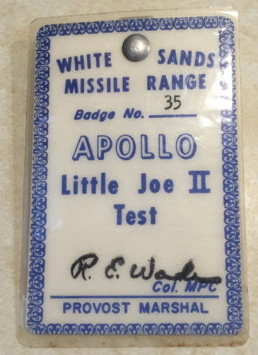
I certainly regard George Gassaway and Tom Beach as the "Little Joe Pros" going back many years so if I seem to step on their toes or seem to repeat what they have said, it is strictly incidental. I have been a Little Joe "nut" since the 60s and have build a number of them. I had access to the Little Joe II at Johnson Space Center since it arrived there in the 70s as I lived just north of JSC...all I had to do was ride my bicycle around Ellington Air Force Base (almost bordering JSC to the north) and I was "there." Recently (well, a little over 10 years ago) when working on the Saturn conservation project at JSC I was able to spend a LOT of time closeup of the thing. I'm well aware that it is pieced together but the pieces are "real" whether actually related to LJ flights or not. Some extra LJII parts (I think fins and some fairings) were, at least 10-12 years ago, were in a JSC industrial location storage area along with some Saturn V "extras". Don't know if that stuff is there anymore and they may either be parts from a "lost" LJ that was produced or simply "spares."

The Wrap

Estes includes a short section of body tube to fill the slight gap around the aft end of the wrap when it is wrapped around the tube. The tube section Estes provides is much too thick. The easiest method to fill the gap is to simply cut a strip of heavy card stock...the way Estes used to do such things in the distant past (I use "cover stock" available at office supply stores...mine is about .11" thick...which is thick enough) and glue it around the aft end of the body tube using white or yellow glue. Some people have recommended plastic strips but you get a far better paper to paper bond than a paper to plastic bond in just about any situation.

One of the very first things I noticed about the kit was that the wrap that was obviously formed from ABS and not regular polystyrene. From fairly extensive experience with ABS in the past I knew regular plastic cements (as, unfortunately, recommended in the Estes instructions) would not work. I have done MANY plastic wraps and have two techniques that I have favored. One is to use transfer tape (sort of an adhesive-only without a backing) and the other is to use a suitable spray adhesive (again, the Estes instructions miss the mark in not prescribing something other than just a spray adhesive). Since the "corrugated" nature of the wrap reduces the contact area available when using transfer tape I decided a heavy duty spray adhesive is perhaps the best solution. I have found two brands in a couple of different formulations each that can do the job. There are the Scotch 3M 77 and 90 sprays and there are the Loctite 200 and 300 sprays. I formerly used the 3M 77 for years but discovered the Loctite 200 is a bit stronger (my opinion...no formal tests to prove it). Both the 3M 77 and Loctite spray smoothly and evenly (the Loctite seems to be a bit thicker. The heavier and stronger bonding 3M 90 and Loctite 300 will work but can be a bit messy because they have "stringy" spray characteristics.

What ever spray adhesive you choose, be sure to mask off the "Service Module" portion of the body tube as well as inside the aft inside portion of the tube. Spray adhesive can (and likely will) unexpectedly find its way to unmasked surfaces. I use 2" Blue painters tape for masking such at this. I also peel off a strip, stick it to a clean surface and then pull it off before masking the model. This reduces the "tack" and makes it easier to remove.

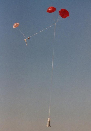
I use a second adhesive (along with the spray) to make for a very strong bond of the wrap to the body tube in the area that the fins attach. The idea is to REALLY securely bond the wrap to the body to hopefully avoid tearing the fin, along with a chunk of wrap, during hard landings (the parachute provided with the LJII kit...as well as most all larger Estes kits the past few years...is WAY TOO SMALL. I recommend making your own 30-36" chute from Mylar (or a lightweight fabric one you can find online) and recovering the body separate from the nosecone). I use "Amazing Goop" Automotive adhesive available at automotive stores. Shoe Goo and Zap Goo seem to be pretty much the same stuff. They are very thick (and potentially messy) adhesives that bond incredibly well to just about anything. I figure anything that can bond metal to paint or hold the soles of my motorcycle boots on for 10 plus years of heavy use has got to have real holding power! But you must clean up any mess made (and you WILL) with the stuff IMMEDIATELY (Bestine, found at office supply stores, does a pretty good cleanup job without attacking plastic).

Clean both sides of the wrap with water and something like Dawn diswashing soap. A good wipedown afterwards with something like 
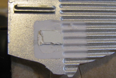
Bestine wouln't hurt. Lay the wrap face up and with the "rear" edge facing you and cut off one corrugation from the far left edge of the wrap. You do this because the wrap is a little long. DON'T cut off a corrugation from the right edge as the seam of the wrap does not center under the tunnel cover (properly positioned, only one corrugation is "trapped" under the tunnel when wraped around the model. Align and dry wrap the corrugated wrap around the body tube and mark a rectangular area that measures about 1" wide and 4" long from the base of the body tube where the fins will mount. Use 2" Blue tape to hold one longitudinal edge of the wrap in place making sure the 1"x4" marked locations align directly under the fin locations of the wrap.

Now, get ready to work quickly. You are going to use both your spray adhesive and your Goo/Goop adhesive...and the Goo/Goop sets pretty quickly. "Swing" the wrap away from the tube using the Blue Tape as the hinge point. and apply a smooth liberal (maybe 1/64" thick or so) coating of your "Goop/Goo" adhesive to the 1"x4" areas. Quickly spray both the inside surface of the wrap and the exposed surface of the body tube with a moderately heavy coating of spray adhesive. Wait about 45 seconds to let the spray adhesive start to take a set and then "swing" the wrap back into contact with the tube. Act quickly and do this on one smooth motion, adhering the wrap from the Blue Tape "hinge" back around to the hinge. Everything should line up. Now lift the last-applied edge of the wrap and peel away the Blue Tape hinge and resecure the wrap.

Don't stop now! Take your 2" Blue Tape and, starting at the rear edge of the wrap, tightly wrap the corrugated wrap over the fin areas and work forward until the entire corrugated wrap is tightly wrapped with Blue Tape. Set aside and let cure for at least 12 hours.

The Blue Tape wrap accomplishes a couple of things. The tight wrap at the rear forces a very tight bond of the "Goop" to the wrap and body tube in the fin areas. Secondly, it forms a tight and uniform bond of the corrugations to the body tube without bonding gaps or voids. And third, it will hold the "gap" where the two ends of the wrap to lie flat and not "pucker" up (this pucker is caused by something called "caternary tension"). I suspect that by covering the entire wrap with Blue Tape you not only securely hold the wrap against the adhesive and body joint until the adhesive cures, but you also trap some of the volatiles against the plastic wrap for a longer period of time which may (theory only) slightly soften the plastic and cause it to set to the curve. Don't leave the tape overwrap on for more than a day or you will have difficulty removing it.

The Fins

Assemble the fins like you would any plastic kit (they are simple polystyrene so any liquid or tube glue will work just fine. Though I saw in earlier posts a recommendation to cut the ejector pads inside the fairing areas flush with the inside surface, I have found it not necessary...but it won't hurt if you want to cut them away. After the fins are assembled and the glue dried, wrap some 220 or so sandpaper around the SM section of the body and sand the root/fairing edges to the curve of the body and also so that you have nice flat and square edges around the periphery of the faring roots that will bond to the wrap corrugations.

You are going to use the "Goop/Goo" type cement again along with a solvent type cement intended for ABS plastic. I use Tenax or Plastic Weld...I think just about every recommendation on this thread covers those two. Apply a very liberal coating of the Goop/Goo all around the inside of the farings. Quickly wipe away any excess of of the stuff that gets on the outside of the part. Also try to wipe it away from the flat sanded edge. Position and secure the fin to the wrap and very liberally go around the joint where the root of the fairing touches the wrap with Tenax or Plastic Weld. Limit the application only to the joint but don't be skimpy. Secure in place with Blue Tape. Repeat this process for the remaining three fins. When the last fin is in place uses a few rubber bands to hold the fin/fairing assemblies tightly against the wrap. No GO BACK AROUND the fairing/skin joints with Tenax or Plastic Weld and set aside "upside down" (fins up and with no pressure on them other than the rubber bands)overnight.

The nice thing about "Goo" type cements is they always remain "flexible" and tough and resistant to "shock" type loads. As I said earlier, I used the stuff on my motorcycle boots years ago (and those boots are my everyday shoes!) and the bond is still going strong...let alone a metal badge on my car that has endured many years of weather, sun, carwashes and more.

Other "Gotchas"

Some may think that epoxy is the ultimate bonding answer but even "roughing up" the plastic-to-epoxy interface really doesn't create the bond you need.

Just because the fins stay on with a "tug test" (your fingers) doesn't mean they will stay on in shock loading cases (I think past posts prove this out).

Don't think you can "go back later" and clean up a glue or adhesive "oops." Clear it up the instant it occurs and you'll be far better off.

If you get a "pucker" of the corrugated wrap seam, DON'T think CA will get the pucker out. CA won't stick to the spray adhesive and all you will end up with is a worse pucker. If you have a pucker (even if you don't) glue the tunnel cover over the pucker with good plastic cement and (again) bind it down, front to rear, with Blue Tape overnight (it's better to do this before gluing the fins on).

I make no guarantees these methods will work for you. They have worked for me for years on other model projects.

Sorry about the length of this post but as I don't visit the various forums I figured I would post what I consider my most important tips for the Little Joe. Who knows when I'll be back? I am also happy answer any emails direct to me (particularly if you want to give me a tongue lashing)

[email protected]
John Pursley
 
Last edited:
What about Plast-I-weld at hobby lobby?


$7.49
Brand: Flex-I-File
SKU: 1025816

HIDE DESCRIPTION
Plast-I-Weld is a water-clear plastic fusing adhesive. This product can dissolve a thin layer on the hobby/craft surface to form a welded joint. It is the latest state-of-the-art approach for making fast, neat, positive, and permanent bonds on ABS, Styrene, Butyrate, and Acrylic plastics.

Its unique “low surface tension” formula assures speedy absorption into the joint, resulting in tight, secure bonds. Plast-I-Weld comes in a Child-Resistant CSA Approved container!

Specially designed for the Touch-n-Flow System.

Net Weight: 2-Fluid Ounces

Seems to be like the other mentioned products???
 
Here is another interesting post I read, I'm not sure about what is said but someone here might know. The site is called Spruebender.net and it's under scale model news then plastic weld.

"I have gone on and tested three types of liquid glueds' and of these three, there are (Plastruct plastic weld,Pro Weld,Tenax 7R). I must say they all work the same. I takes you holding two plastic part together from three to ten seconds for a full bond. Now if any of you can't afford a can of MEK-(Methyethylketone) get one of these that I have show here. They all work the same and work in the same amount of time. They all will bond ABS to Styrene plastics. Now I must warn you that the smell of the Plastruct glue is the strongest."


2nd copied post
"The active ingredient in Tenax and the other manufacturer's solvents that "weld" polystyrene is methyethylketone or MEK.
You can purchase pint, quart, or gallon quantities of MEK at Lowes, Home Depot, or other paint retailers.
Just be sure that what you buy is MEK with no other additives. I would also suggest filtering it through cheesecloth or even a coffee filter so you don't get small particulates caught in your touch-n-flo applicator.

By a small quantity and try it first."
 
Congratulations on the successful flight James!

The capsule chute failed to open, yet the entire capsule and tower assembly was recovered intact in the tall grass.

This is part of why I like to use the semi-drogue method, as the thing that inspired me to use semi-drogue in the early 1980's was to see one part of our team's scale model plummet with a non-deployed chute while the other part merrily came down under a chute (in that case, the main body had its chute jammed inside, while the nose section came down on its chute. Had thy bene tied together at the least it would not have hit too hard and not been DQ'ed, and possibly could have yanked the main out like most real drogue chutes do).

So, I tie everything together, and they do not bang into each other as the airflow tries to push them apart horizontally and the cord lengths do not have the main body and nose at the same lengths from the main (in case the main opened but drogue didn't). The models I've used this semi-drogue method with...... if the nose ejects at all, to let the drogue get out, it has had a 100% success rate for many many many flights of various models.

I WAS going to mention the semi-drogue method after last week's flight, which I expected to have a really nice photo of the model slowly descending using the semi-drogue method to show what I meant. Sigh. So, here's an oldie instead:

xPerNH9.jpg


The image above was from NARAM-34. The twin main chutes, I wish I had had extra elastic so I could have had each one with a few feet of its own elastic, above the know where bother were tied together. I did that for most other flights using twin mains. For the flight last week, I was using an 18" "drogue" on the BPC/Capsule, and a 36" nylon chute for the main chute, same sort of shock cord arrangement for semi-drogue.

BTW - Another big tip. Fill the inside of the BPC ("Capsule") with some light material, or even a lightweight bulkhead (foamcore, 1/16" balsa, poster paper, etc), so that the packed parachute does not end up "Ice Cream Coned" inside of the cone during descent, never getting into the airflow. I know I can recall SOME model that did that at least once, and I've tried to be careful to avoid that with Little Joe-II's. And yes I did that last week, though it had no chance to eject.

Oh, I also had an "ice Cream Cone" happen with a Joe test flight when I had a semi-scale Apollo CM hidden inside, under the BPC. I had to rig up a method to make it come out from inside of the BPC and fall free, to deploy its own three chutes.

- George Gassaway
 
Last edited:
John Pursley, GREAT to see you post here!

This thread is meant for everyone, so it's nice to see your comments, suggestions, and such.

Was really glad to see the vinyl wraps you've done up. If I want to have a more weather-resistant or more robust set of wraps for a future model, I may get your wraps (the paper wraps will not do well if they land on wet grass or otherwise get wet).

It is incredible to hear that some left over Joe parts are, or at least were, at JSC. Can you recall if the fins were fixed, or movable? There was one unaccounted for Little Joe-II, 8 built, 5 flown, 2 on display. Seems like the main body was scrapped, no factual info, just it went "poof" (or possibly it was cancelled, as the missing one was 12-50-4, and they quickly went from the fixed fin 12-50 series to the movable fin 12-51 series. If it was cancelled it might have been in time to build it into the first 12-51 series). If the left over fins are fixed fins, then those may be fins meant for 12-50-4.

- George Gassaway
 
Well, THIS is interesting:

pI5Xpv9.jpg


Just $405.99 and it's yours: https://tinyurl.com/gtobc5c


On the flip side, this was posted in the "Space Hipsters" group on FaceBook:

3GxMO1G.jpg


The space equivalent of the Leg Lamp in "A Christmas Story"

The person who posted it, found it in a thrift shop and did not buy it!

Price, $5!

Hardly anyone could believe he didn't buy it. He finally went back and bought it for a friend in that group.

Relevance here? Hmmmm. DIY Rocket Lamp, using a 1/45 Little Joe-II? :)
 
Last edited:
George

I think a few of these will show up entered in Sport Scale and was wondering if you could make a few suggestions
on details to add to this model build, which would make it stand out in Sport Scale from just the basic kit…

I am building this as an A-004 and have already worked on the recruit motors like you showed in the
build thread and will be using the wraps from John and just looking for a few other ideas…

Thanks

Dan

Dan, George addresses how to make the LJ II to a truer scale kit in Post #6 in this thread. I'm sure he could tell you more.

paul
 
think a few of these will show up entered in Sport Scale and was wondering if you could make a few suggestions on details to add to this model build, which would make it stand out in Sport Scale from just the basic kit…

Well..... that can begin a slippery slope of how far to go.

For example, if one chooses to build it as A-004, and does the 4 Algols and 2 custom made Recruits, then the main Joe body itself is pretty accurate. Some extra detailing can be done such as the three access panel doors near the top, and the antennas on the corrugations, but those extra details are sort of minor and do not jump out as "missing" if they are not there.

So, I think the main area to focus on is the BPC. The four hollow holes that the legs are glued into, are great for assembly. But just jump out as not being accurate (this is a legacy of the original Centuri kit). The real Apollo CM's forward BPC had some rectangular-ish fairings (had slightly sloped sides) over the base of the tower legs.

hItnRHY.jpg


On my 1/39.5 scale models, I used some square cross-section Plastruct or Evergreen plastic tubing, cut it to an angle, and hand drilled the holes if they were not big enough (Probably was Plastruct's which has a small round hole). Now in that case my tower legs were 3/32" without any bumps or bulges. So, to do this for the 1/45 kit would require having the pieces with a hole big enough to allow for the wider bulge of the tower legs near the base, then to go back later after complete assembly to fill in the gap between the larger hole and the thinner leg.

So, if someone had asked what one thing to upgrade, that would be my suggestion.

Second on the list would be to modify the "cone" to look more accurate. It looks rounded at the edges like an Apollo CM. It does not extend to be a bit wider than the SM and most importantly does not have a mostly vertical edge, with a sharp 90 degree corner at the bottom, like the BPC.

QdigQwi.jpg


Now, that would be a lot more involved to do than the tower leg fairings mentioned above. If I tried, I might take a strip of .04 to .06" thick styrene (.04" may be about right), cut to a width a little less than the height of the cylindrical portion of the BPC base, and glue that around the base of the cone. After drying, apply plastic putty to fill in the rounded area of the cone base, so that after drying it could be sanded down to extend the conical section diagonally to the outer edge of the styrene strip.

Next priority, 3D details on the BPC. The Umbilical Connector between the CM and SM, which the BPC cover fit over. Also, parts of the BPC that stuck out to fit over the two CM Scimitar antennas, and two half-round bulges to allow for vents to be able to vent properly.

To go into more detail, would then interfere with using wraps. The BPC Splice seams had some thickness to them above the surface of the rest of the panels. On my models, what I did was to use some THICK white decal material, cut to the proper width, to represent the splices. However, I think for the NARAM-33 model, I may have used .005" thick plastic rather than thick decal. In any case, those were applied before painting, and then the black roll markings (hand cut out of black decal sheet) were applied over them, the "stepped" thickness difference appearing correctly.

QKfqGmz.jpg


In the photo above of my NARAM model, it was built before all of the magazine data was completed. I had the scimitar antennas, and the BPC side of the umbilical connection, but didn't have the half-rounds for the vent tunnels, and did not have the rest of the umbilical on the SM. You can see some of the BPC Splices in the pic, the rest is washed out in the lighting.

See these drawings for more info:

https://georgesrockets.com/GRP/Scale/DATA/Joe_GIFs/BPC-LES.gif

https://georgesrockets.com/GRP/Scale/DATA/Joe_GIFs/BPC-1.gif

Now, when I said slippery slope, here's where the skids get greased. The wraps are GREAT for sport models. They are not as good for contest scale models as compared with a model that has true details and true markings. However, a person would need to be able to do those details and markings well to begin with, as poorly done custom work just does not hold up well compared to less detail done neatly. but if a person wanted to build a 1/45 model to try to beat other 1/45 models, and had the skills and time to do it, custom work would be better than wraps.

I've seen other Joe model with wraps entered at NARAM. The wraps looked a bit cartoony. Because they were not intended to be used for high quality scale models (indeed they were never drawn for the purpose of being a "Wrap" for a built model, they were done as "detail maps"). So, anyway, the wraps I drew up or modified from the old drawings, I did try to make them look a bit better by reducing a lot of the thickness of most lines. And changing a lot of lines from black to shades of gray. John Pursely has done similar with his vinyl wraps. So, they look a bit better, a bit more realistic. But not photo-realistic. Not as good as the same details and markings being modeled in the conventional ways rather than wraps.

- George Gassaway
 
Last edited:
On the NAR's Facebook page, Daniel Cavender posted a couple of photos of a 1/45 display stand for the Little Joe, representing the tower on the launch pad. It uses lasercut plywood parts.

Just cut one of these out of cheap 1/4" plywood. That required a bit of file work to open up some of the holes, but that task just took a couple of minutes. Can't wait to prime and paint it bright yellow!

IMG_1790.jpg
 
George

Thanks...you the man...:) :) ....lots of good insight...

Looks like I will work on the capsule... That slope wasn't that slippery...it is just Sport Scale...

Dan
 
George,

I saw the stored "Little Joe parts" (They were under tarps) when I was working on the Saturn conservation projects. I didn't think much about them then (famous last words). As with so many "whirlwind visits" to various and sundry locations when looking for Saturn parts (snooping around) I didn't stay long enough to truly identify or photograph (it was dark in that area) anything. As I recall, I was looking for escape tower parts, BPC and the flyaway umbilical cover for the CM/SM that I was working on at the time. My intentions were to go back and look at more but never got back. Right about that time I was asked to go to Huntsville for the assessment and Saturn project start there. Gotta tell you my "Indiana Jones" story about exploring the "vaults" and woods at Marshall sometime before I get to senile to remember anything.

The wraps are working out quite well. Look better on a "scale" model than I thought they would. Of course the "details" on the LJ wraps make it look better for the casual non-competition flyer. The main benefit of the wraps to me are easily achievable positioning and alignment and super simple application when compared to water slide decals.

I should probably find some Mercury Redstone threads here and rah rah the Mercury Redstone skin kits...

John Pursley
 
That slope wasn't that slippery...it is just Sport Scale...

You know how to build a winning "sport" scale model?

Build an accurate highly detailed model. :)

My contest Joe models were all built for Sport Scale. Although the ones used for regional contests were not as detailed or accurate. My Space Shuttle was built for Sport Scale, though it scored pretty decently for dimensional accuracy when I entered it in two WSMC's

The one aspect where sport scale vs measured scale helped was in fudging some diameters. The LES motor on my 1/39.5 models was a bit larger in diameter than it should have been, as there was no suitable size tube I could find at the time that would be the right diameter. But by eye, judges could not tell. Later I did find one that was a lot closer, 5/8" Plastruct tubing, but never built the new model I was going to use it with.

- George Gasaway
 
Adding Fin Spars to the Little Joe for Strength (and Peace of Mind...)

Though in an earlier post I described a dual-adhesive method to use on the corrugated wrap and fins. Building multiple Little Joes, I wasn't satisfied with the fact that even if you got the fins strongly glued to the wrap, the wrap itself is not an ideal item on the model to be gluing something with high structural requirements to and you were still depending on a less than ideal bond between the backside of the wrap and the body tube.

With the easy addition of just four easy-to-make parts and an easy change to the assembly of the model I think the all-too-common shearing of the fins from the model when landing (or just accidentally dropping it) can be resolved.

Perform the following process after you apply the wrap to the body tube but BEFORE installing the engine mount.

Purchase a 1/4" hardwood dowel at your local hobby or hardware store. Don't cut it to the four lengths needed now. It's easier to make one piece at a time and then cut it from the long dowel after gluing it into the fin/fairing assembly. Shape it as shown in the photos. It will look sort of like a screwdriver blade.

WP_20160307_17_32_47_Pro (Small).jpg WP_20160307_17_33_14_Pro (Small).jpg

Test fit the dowel into the fin assembly positioning it as far to the rear of the assembly as possible. Also sand the "screwdriver blade" on the dowel until it reaches to the molded actuator housing. Once satisfied with the depth and fit of the dowel glue it in place at right angles to the root edge of the assembly. This is one of those instances where CA works well. I "wick" thin CA along the sides of the spar inside the fin and then follow up with an application of thick CA around the spar inside the fin. I use a drafting triangle to assure the spar is at right angles to the assembly root edge.

WP_20160307_17_36_26_Pro (Small).jpg WP_20160307_17_39_51_Pro (Small).jpg

Measure and mark the dowel 1" from the root edge of the fin assembly and then use a draw saw (or whatever your preference) to cut the dowel.

WP_20160307_17_46_16_Pro (Small).jpg

Drill a 1/4" hole in four places centered exactly on the fin/fairing centerline with the hole center located 9/32" from the rear edge of the body.

WP_20160307_17_57_10_Pro (Small).jpg

At this point you will probably decide upon an assembly sequence to suit yourself. I would build up the engine mount and NOT glue the rear bulkhead in place. Install and glue the engine mount (with the rear ring in place but not glued to the mount) gluing only the forward ring in place. The end of the engine tube protrudes about 1/4" beyond the end of the main body tube (give or take) or you can even make it flush with the rear of the main tube if you so desire. Leave the rear bulkhead in place but unglued to hold everything centered until the glue inside the body tube on the forward bulkhead has dried then remove the rear bulkhead. At this point you might want to apply an extra fillet to the backside of the forward bulkhead/body tube joint. This is an opportunity you don't often get with "regular" engine mount installation practices.

Install the four fins by inserting the spar through the 1/4" hole. Use a good glue and method as described in earlier posts in this thread to glue the fin/faring assembly to the wrap. Apply a bead of white/yellow glue around the dowel at the root of the fin/fairing assembly before gluing the fin/fairing assembly in place. Make sure all four fins project straight away from the body. Wrap rubber bands (or blue tape) around the body over the fairings to hold the fin/fairings tightly against the body while the glue dries. Apply a fillet of glue around the spars on the inside of the body tube.

WP_20160307_17_58_02_Pro (Small).jpg

After the glue has dried holding the fin/fairings to the wrap apply a bead of glue along the rear facing centerline of the four spar dowels (I use white or yellow glue because it gives you "working time.") Run a bead of glue around the inside of the main body about 1/8" inside the tube. Slip the rear bulkhead over the engine tube and rotate it so the scale engine holes in the bulkhead are properly positioned and then push the bulkhead into place against the glue on the spar dowels. Apply a fillet of glue around the rear bulkhead at the engine tube. Let everything dry.

Finish assembly of your model.

WP_20160307_17_58_32_Pro (Small).jpg WP_20160307_18_18_18_Pro (Small).jpg

I'll bet you'll rip the whole side of the model off before you shear a fin off!

There are a couple of structural advantages with this modification. One, the fins are very rigid and don't depend on the hoop rigidity of the body tube nor entirely on the glue interface between the wrap and the fin/fairing nor between the wrap and the body tube. Also, the spar passes through the body tube where it has been strengthened by the extra body tube thickness from the kit-supplied ring (see previous posts in this thread) or, better, a couple of wraps of strips of card or cover stock in place of the ring. Also, the spars protruding through the model almost to the engine tube and glued to the inside face of the rear bulkhead greatly strengthens the engine mount.

You'll be adding maybe 8-10 grams of weight to the model which is not a great sacrifice to pay for the improvements in strength and survivability of the model from flight to flight.

Painting and Decal Tip

Silver or metallic paints are almost almost always affected by the application of clear coatings...frequently in a negative or unexpected way ranging from slightly changing the "color" to outright destroying the metallic paint coat. I have used water-based acrylic over metallic paints for years with great results. My favorite is good old Pledge Floor Polish (formerly known as Future Floor Polish). A 27 ounce bottle will set you back maybe $12 but 27 ounces will last forever. Apply it straight with a high volume airbrush or a high quality artist's foam rubber brush (a technique for discussion some other day).

Apply a clear coat and allow it to dry to the metallic corrugated body BEFORE you apply the "UNITED STATES" decals. After the decals have been applied and dried, apply one more coat of clear over the decals and body.

As in my earlier post, you can visit eBay and look for "Estes Little Joe" and you will find my (ACCUR8) skin kit which covers almost the entirety of the "white" poritions of the model. If you can't find them on eBay, just drop me a note at [email protected].

John Pursley
 
Having had the opportunity to go up alongside the Little Joe on display at Johnson Space Center (and touch, lick, smell...or whatever a scale modeler might do) one small and easy "improvement" to a competition model would be to paint the forward ring and the middle ring on the wrap a slightly "goldish silver" or "copperish silver"...or use a "stainless steel" colored paint. Make those rings just a little bit different but don't go overboard. Those bands are actually splice rings and from my closeup observation they AREN'T aluminum like the rest of the body but are much harder and corrosion resistant (just about everything on the JSC Little Joe has corroded other than those rings) than the aluminum of the rest of the vehicle.

John Pursley
 
George

Do you have any dimensions on the upper section of the BPC..??

looking for info to make a master to vacform over just the tip of the cover, which would include the tower leg fairings.

you have a nice drawing showing it, but no dimensions..

Thanks

Dan
 
George

Do you have any dimensions on the upper section of the BPC..??

looking for info to make a master to vacform over just the tip of the cover, which would include the tower leg fairings.

you have a nice drawing showing it, but no dimensions..

Do you mean more than this drawing shows? It has dimensions, and I linked to it in message #201 with the other BPC upgrade notes.

BPC-LES.gif


I do not think we ever had a diameter for the base of it, but of course there is the vertical distance which defnes the width where it intersects with the sloped sides. I think for my models I measured off of the drawing what that width (base diameter) would be, and compared that with the known diameter of the BPC base diameter (156") to derive the diameter for a model.

If you want, I'll open up an old file and measure out what that diameter should be for full size and convert for 1/45. Can't right now since I have to use my old G5 desktop running an old OS to open those files, I'm using my laptop elsewhere.

Here is a reminder again of Little Joe II data on my website, this is the drawings page

https://georgesrockets.com/GRP/Scale/DATA/LJoeData.htm

And this page about my models, which lower down has info on how I built some of them:

https://georgesrockets.com/GRP/Scale/DATA/George.htm

At one time I was going to build a new model and upgraded some of the parts. Two key upgrades were cast parts, one for the forward BPC, and one for the LES skirt to fit .625" Plastruct tubing for the LES motor. The master part for the Hard BPC was made from a spare Vac-form of the cone used for the whole BPC, which after cutting to a smaller diameter matched the diameter of the hard BPC (upper BPC). On the real thing the hard BPC was about one inch thicker than the rest, so there was a 1" step. Anyway, I added the angle-cut square pieces for the tower leg fairings, drilled to 3/32", and then made an RTV mold so I could cast copies of it. So, in the photo below, you can see a couple of the cast forward BPC's, as well as a cast LES skirt (the cast parts are light tan in color). Also in the pic you can see the jig I used for helping to built the tower.

- George Gassaway

IMG_3747.JPG
 
Last edited:

Latest posts

Back
Top