Bolaero-Endgame

The Rocketry Forum

Help Support The Rocketry Forum:

This site may earn a commission from merchant affiliate links, including eBay, Amazon, and others.
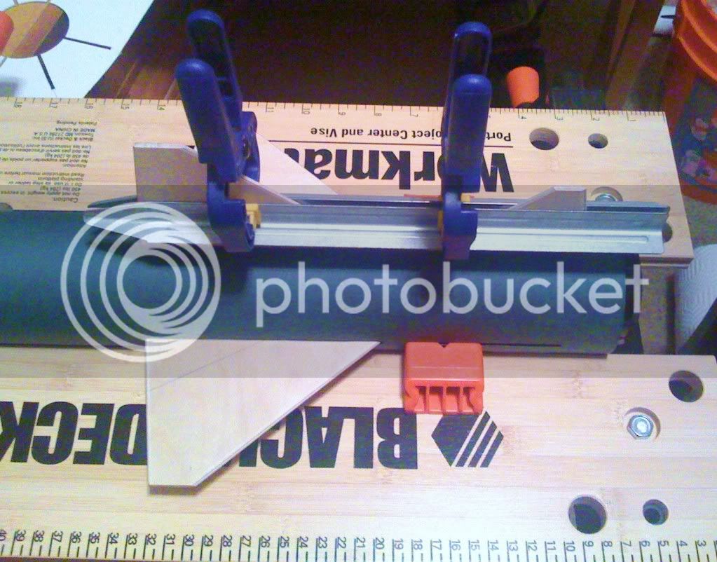
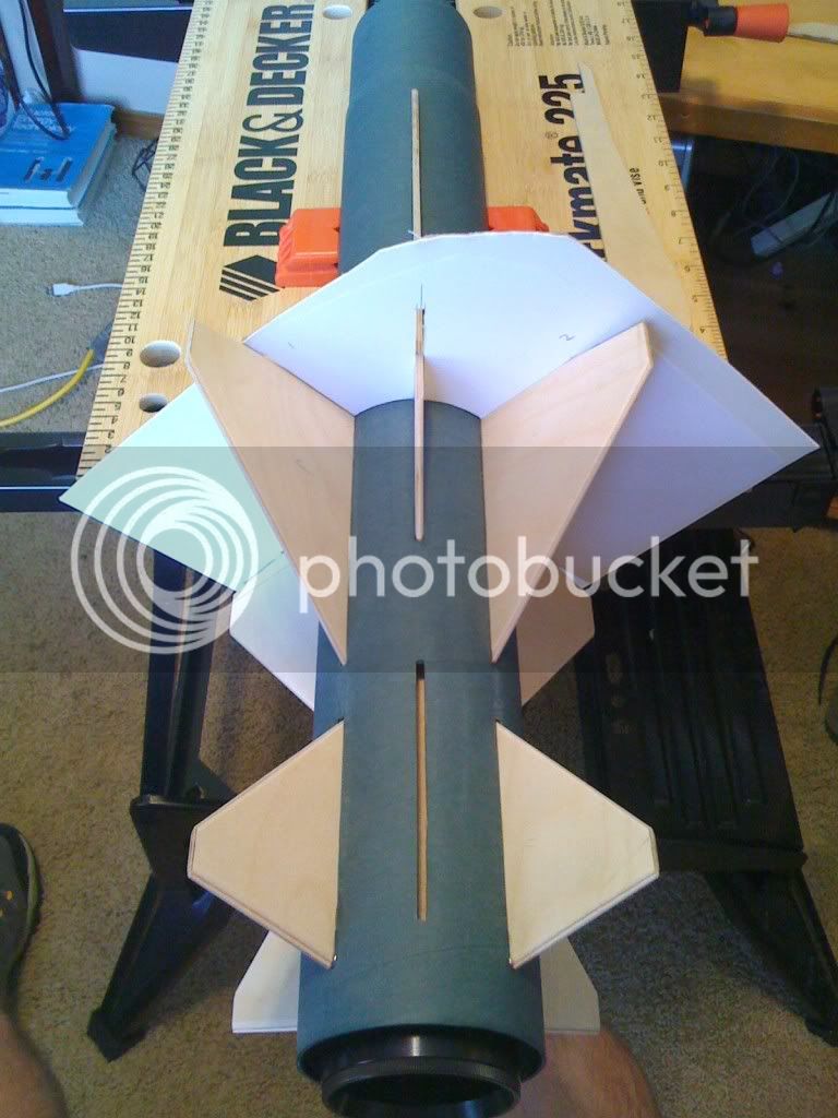
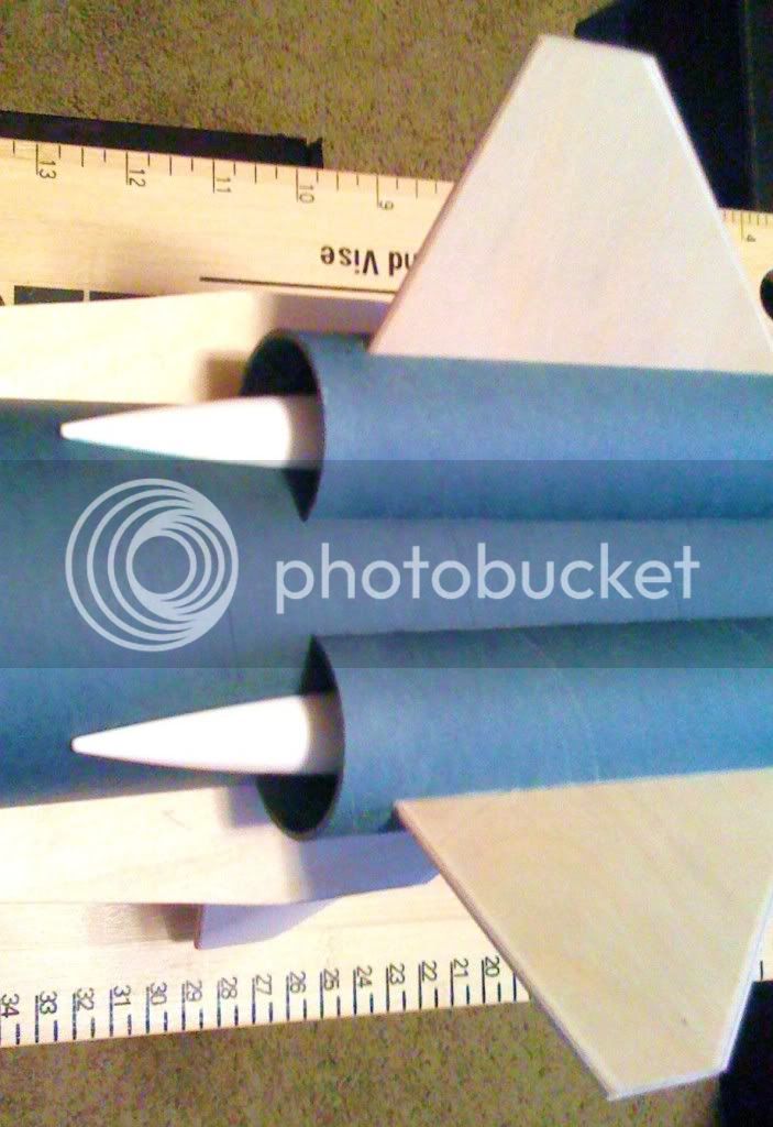
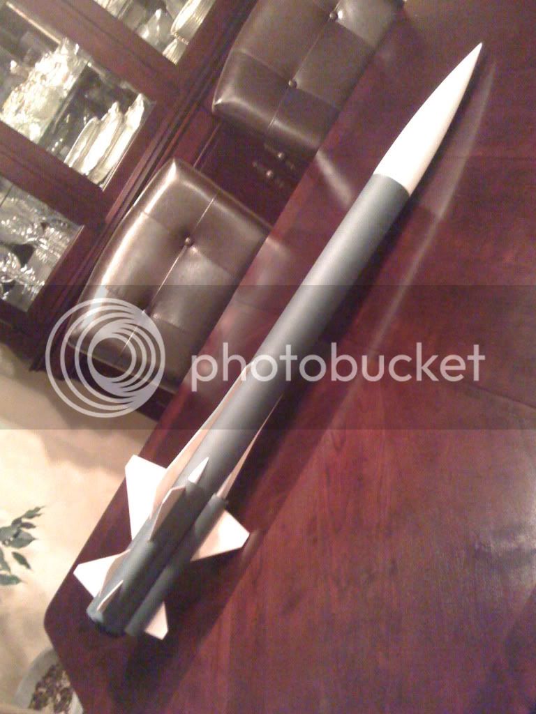
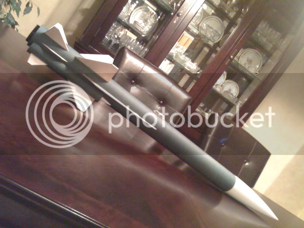
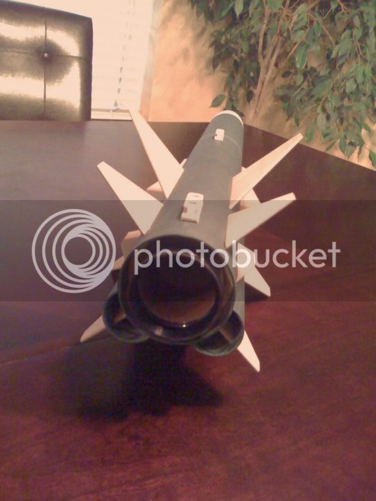
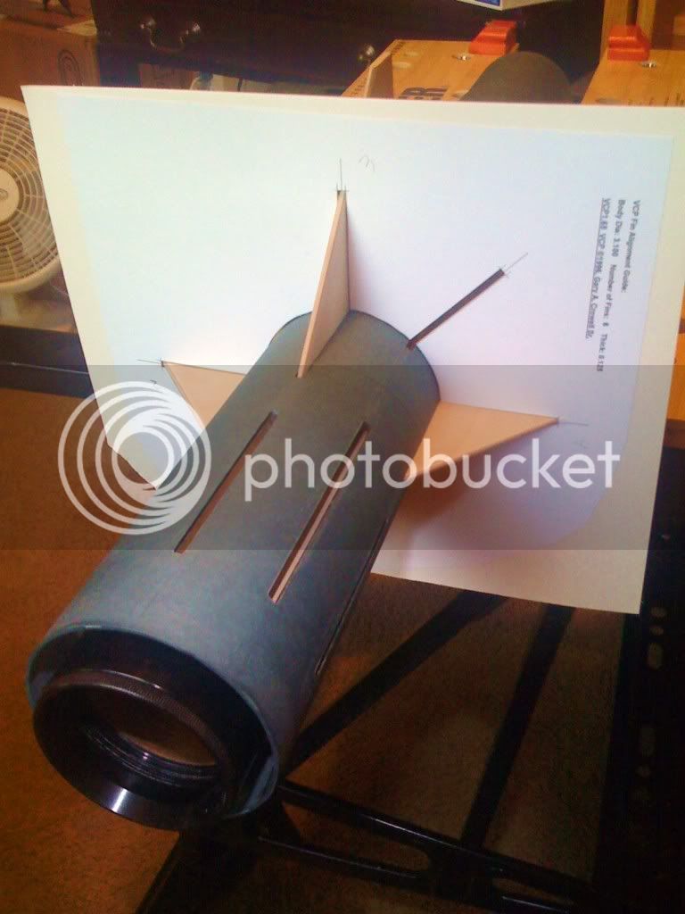
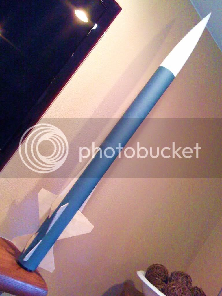
It's starting to take shape. I got the fins sanded and airfoil shaped the leading and trailing edges. I printed out a fin alignment jig, spray mounted it on poster board, cut it out and started installing the fins. I currently have 3 of the forward fins installed and am waiting on the epoxy to set up so I can do the next one...

_________________________________

062.jpg
 
Of course, I got impatient and had to put it together for the manditory dry fit photo. This shot does not yet include the ramjet nacelles, which will make a huge difference in the appearance, but I am pleased with the result...

______________________________

029a.jpg
 
Last edited:
Very nice! I may think about trying to do a low or mid power downscale of that.:)
 
Before I went to bed last night I finished installing the forward fin set and got a couple of the aft fins on. I used the template to get the forward fins aligned and then I indexed the aft fins off of the front fins as pictured below.

__________________________________________

075.jpg
 
The trickiest part of this build will be fabricating the ramjet nacelles. I started to work on those yesterday afternoon. I used a couple of old plastic Estes BT-20 sized nosecones from my big box-o-rocket parts and sanded them down on one side with a disk sander. I got close to the shape I wanted with the sander then wrapped some sandpaper around a piece of 4" airframe tube to get the final shape just right. I still have to cut a slot in each one where it will fit over the forward fin, but here's what I've got so far...

____________________________________

056-1.jpg
 
And I used a Dremel tool to cut the 1.5 inch tubes to the shape I wanted. They are a little more than one half of the full circumference. Here's sort of how they will look when attached to the main airframe...

______________________________

063.jpg
 
EVERYONE LOOKOUT STEELEYEYED IS ON A BUILDING SPREE!!!

Looking great as usual!

-Dave

______________________________________

Thanks Dave. This is too much fun. My favorite thing in rocketry is final assembly of a new design and seeing it come together for the first time. They always look much better in "living color" than they do in RockSim 3D graphics. Hope this one flys better than that tragic event you witnessed last year...

Bret
 
Okay, I got all the fins and strakes epoxied in place today. While all that epoxy was setting up I cut the slots in the intake scoop tubes and notched the plastic nosecones so everything would fit over the fins...

______________________________________

234.jpg


235-1.jpg
 
Last edited:
Looking good! You're right, the ramjets change the overall look quite a bit.
Reed
 
Looking good! You're right, the ramjets change the overall look quite a bit.
Reed

__________________________________

Thanks Reed. Here's a shot of the "bottom" side showing the two ramjet nacelles. Tonight I'm working on the fillets (there 40 of them to do on this design!)...

__________________________________

250.jpg
 
Dude, you are a rocket buildin' Machine! Very nice!

How'd the "tubs" work out on the MMT? Did you use syringes or something to inject through the BT and pool up the epoxy then drop the fins in?

Fin Tubs.jpg
 
I'm curious as to how your CG/CP worked out. All those cool fins 'n stuff are adding weight to the wrong end. Did you have to add any nose weight?

-Dave
 
Dude, you are a rocket buildin' Machine! Very nice!

How'd the "tubs" work out on the MMT? Did you use syringes or something to inject through the BT and pool up the epoxy then drop the fins in?

Thanks Monkey. The tub technique worked beautifully. I thought I was going to have to use syringes to inject the epoxy into the fin slots. Turned out that I was able to pour the epoxy from the little plastic cups that I mixed it in directly into the slots (by bending the edge of the cup to a point). I could actually see how much epoxy was filling the tubs by shining a flashlight into the slot. I filled it to the desired depth of about 1/8th inch, then I dropped the fin into the slot and slid the alignment guide over it. Simple, easy, effective... I will use this technique again.
 
Im thinking a LARGE version of this is in my future. Its just too cool to pass up!

Ben
 
I'm curious as to how your CG/CP worked out. All those cool fins 'n stuff are adding weight to the wrong end. Did you have to add any nose weight?

-Dave

_____________________________

Dave,
It's too early to definitively answer your question on the CG, however, the CP is located at the leading edge of the forward fins. With no motor and no parachute/shock cord in it, the CG is 7+ inches ahead of the CP (2.4 calipers). I still have some work to do that will add weight to both ends of the rocket. I only have 8 of the 40 fillets done as of last night. I plan on making the nosecone screw on and off so I can gain access to the shock cord mount in the upper airframe, that will add a little nose weight. After I finish up and put a parachute, shock cord, and associated hardware in it (and try a couple of different motors) I will see whether additional nose weight is needed for the motor based ejection configuration. Note, however, that I intend to build a modular avbay that will allow me to convert it to dual deployment. If I'm ever going to put a K570 in it I want DD recovery.

Bret
 
Im thinking a LARGE version of this is in my future. Its just too cool to pass up!

Ben

__________________________

Ben,
I have already ordered some of the parts to build a 6" version of this rocket. I'm going to build the airframe with Blue Tube. It will have a 75mm MMT, G10 fins and avbay with dual flight computers and a Garmin Astro GPS transmitter. I thought about a 7.5" version, but decided that's more than I want to build for now, but who knows...

Bret
 
Tonight I got 8 more fillets done and I figured out how I wanted to attach the nosecone and shockcord in the upper airframe. I mentioned above that I wanted to make the nosecone screw on/off. The reason for this is to be able to access the shock cord in the upper airframe tube and be able to conveniently add nose weight if needed. The photo below shows two pieces. The item on the left is a short piece of coupler tube bonded to a 1/4" bulkhead. On the right is a 1/4-20 screweye attached to a smaller bulkhead. The later has 4 each #8-32 T-nuts attached to it. The larger bulkhead (on the left) will be epoxied into the forward airframe. Using an allen wrench and four #8-32 screws I can attach or remove the smaller screweye bulkhead. The 1/4-20 threaded shaft of the screweye extends approximately 1/2 inch beyond the nut that holds it in place. I installed a threaded sleve in the base of the nosecone so it can now be screwed on to the screweye when it is installed in the bulkhead.

_________________________________

082.jpg
 
The bulkheads/screweye assembly epoxied in place is shown below. The nosecone plugs in this end and screws down onto the screweye.

_____________________________________

085.jpg
 
Back
Top