You are using an out of date browser. It may not display this or other websites correctly.
You should upgrade or use an alternative browser.
You should upgrade or use an alternative browser.
Apollo LES 4"
- Thread starter g_boxwood
- Start date


Help Support The Rocketry Forum:
This site may earn a commission from merchant affiliate
links, including eBay, Amazon, and others.
g_boxwood
Well-Known Member
- Joined
- Jan 20, 2009
- Messages
- 564
- Reaction score
- 0
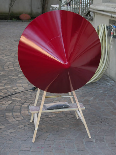
It's priming day as well!
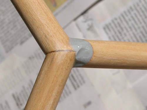
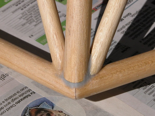
One last thing I didn't point out is that I never invested that much in shaping the intersection at the vertex members of the launch stand!
I went for local shaping of thickened epoxy + filling and sanding...
One last thing I didn't point out is that I never invested that much in shaping the intersection at the vertex members of the launch stand!
I went for local shaping of thickened epoxy + filling and sanding...
g_boxwood
Well-Known Member
- Joined
- Jan 20, 2009
- Messages
- 564
- Reaction score
- 0
Here I am! For those thinking about me having quit this project... I salute you!
Most of the time was dedicated to
. finishing the plugs
. making some of the molds
Those are the kind of activity that makes you wonder why you volounteered for such a long and painstaking torture!
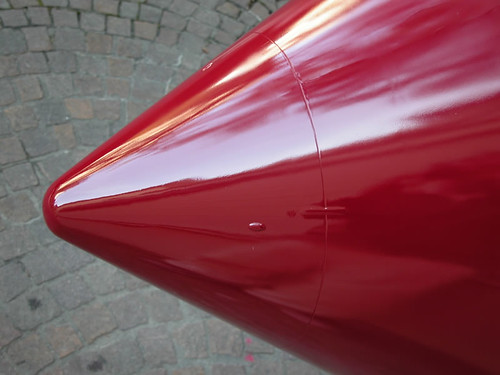
I also added a few compulsory references to the capsule:
. the split line between the capsule and its tip
. 2 styrene tabs (1 between the capsule and the tip and the other between the capsule and the heastshield)
. 4 little bulks that lock the BPC to the capsule
They all aid in giving a permanent coupling reference between the tip, the capsule, the BPC and the heatshield.
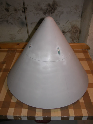
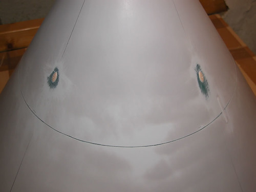
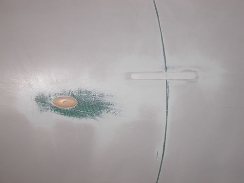
Drawing and scribing the split line took me a while and this is what I came up with...
Most of the time was dedicated to
. finishing the plugs
. making some of the molds
Those are the kind of activity that makes you wonder why you volounteered for such a long and painstaking torture!
I also added a few compulsory references to the capsule:
. the split line between the capsule and its tip
. 2 styrene tabs (1 between the capsule and the tip and the other between the capsule and the heastshield)
. 4 little bulks that lock the BPC to the capsule
They all aid in giving a permanent coupling reference between the tip, the capsule, the BPC and the heatshield.
Drawing and scribing the split line took me a while and this is what I came up with...
g_boxwood
Well-Known Member
- Joined
- Jan 20, 2009
- Messages
- 564
- Reaction score
- 0
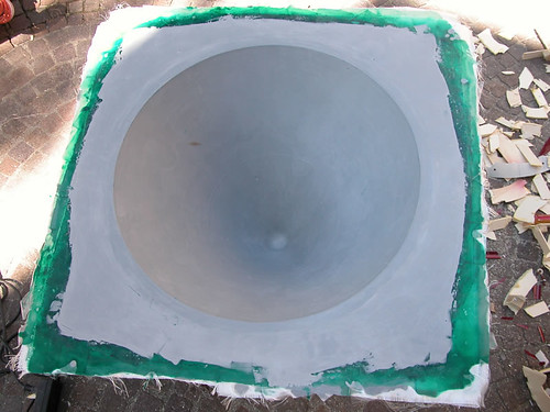
Making the molds.
I need to make 3 molds: the capsule, the heatshield and the booster skirt.
The capsule and the heatshield share the same parting board so I have to make one at the time.
Being the capsule the biggest I started with it along with the way smaller booster skirt.
The process was long and painful and I did not take (m)any pictures.
Plug preparation involved 2 layers of priming wax (1 per day) and 2 layers of PVA release agent (1 per day) = 4 days lost + 1 more day for total drying.
Lay-up involved the following coats:
. 1 layer of microballoons-thickened resin (home-made gelcoat)
. 1 layer of f/g cloth in the 200 gr range
. 1 layer of core material in the form of 5 mm thick absorber
EVERY layer needs the previous one to be partially cured so take your time and wait for the resin to be tacky!
It took me one daylight to complete and almost 5 kilos of resin (yes, thank you absorber!)...
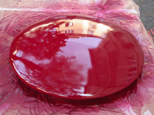
Results are satisfying, parting the smaller booster skirt was a breeze: the double PVA layer peels off like a strong film!
Shiny mold, as expected!
I need to make 3 molds: the capsule, the heatshield and the booster skirt.
The capsule and the heatshield share the same parting board so I have to make one at the time.
Being the capsule the biggest I started with it along with the way smaller booster skirt.
The process was long and painful and I did not take (m)any pictures.
Plug preparation involved 2 layers of priming wax (1 per day) and 2 layers of PVA release agent (1 per day) = 4 days lost + 1 more day for total drying.
Lay-up involved the following coats:
. 1 layer of microballoons-thickened resin (home-made gelcoat)
. 1 layer of f/g cloth in the 200 gr range
. 1 layer of core material in the form of 5 mm thick absorber
EVERY layer needs the previous one to be partially cured so take your time and wait for the resin to be tacky!
It took me one daylight to complete and almost 5 kilos of resin (yes, thank you absorber!)...
Results are satisfying, parting the smaller booster skirt was a breeze: the double PVA layer peels off like a strong film!
Shiny mold, as expected!
g_boxwood
Well-Known Member
- Joined
- Jan 20, 2009
- Messages
- 564
- Reaction score
- 0
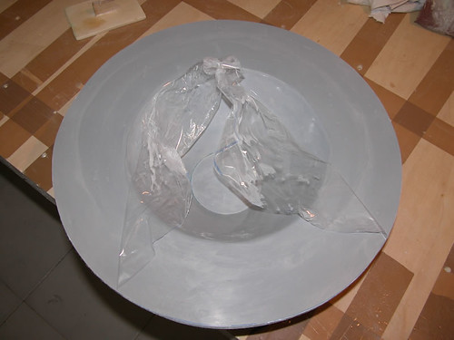
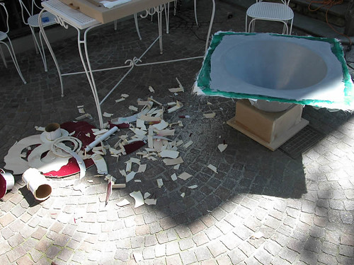
DISCLAIMER: the following contains scene of extreme violence. You must be 18 or older to watch.
Not the same applies to the capsule. I was expecting some more 'work' but it suddenly turned out that common techniques were out of question.
I made some mistakes planning this mold but I really wanted it in one piece, so what follows is the price to pay.
I started by removing the parting board exposing the base of the capsule.
Next came the internal surgery: removing the frame served to 'soften' the outer skin so it could be flexed and extracted. It worked and I saved the skin.
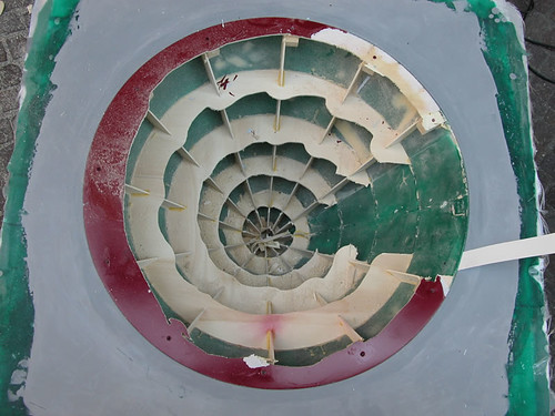
I wanted to make the plug flyable after its duty... and I did!
Not the same applies to the capsule. I was expecting some more 'work' but it suddenly turned out that common techniques were out of question.
I made some mistakes planning this mold but I really wanted it in one piece, so what follows is the price to pay.
I started by removing the parting board exposing the base of the capsule.
Next came the internal surgery: removing the frame served to 'soften' the outer skin so it could be flexed and extracted. It worked and I saved the skin.
I wanted to make the plug flyable after its duty... and I did!
g_boxwood
Well-Known Member
- Joined
- Jan 20, 2009
- Messages
- 564
- Reaction score
- 0
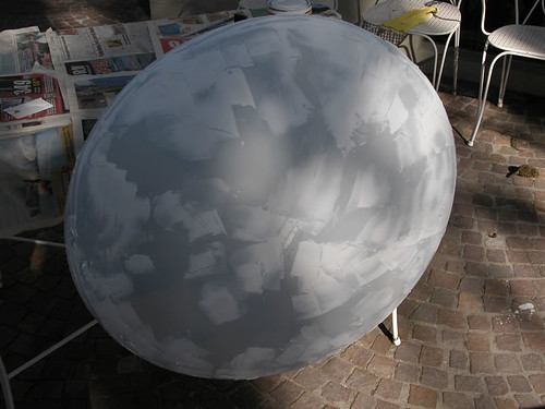
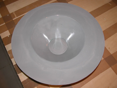
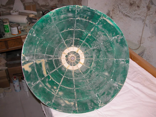
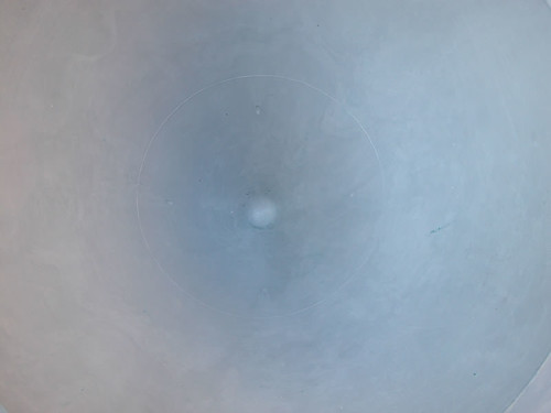
The mold is superb and HUGE, the PVA film is still in place and that is why it doesn't shine.
Raw:
Trimmed:
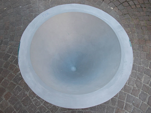
All the details transferred nicely:
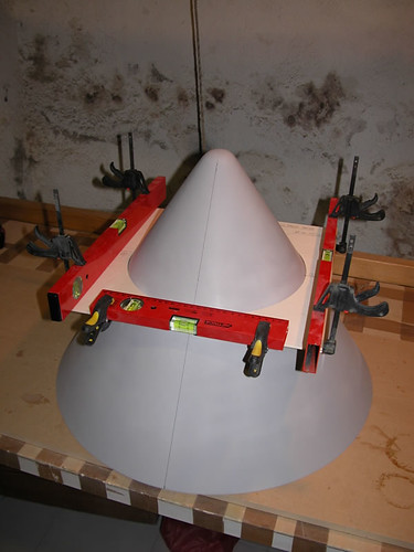
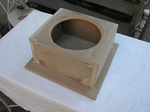
I also built a base to hold it upside down while working into it:
Raw:
Trimmed:
All the details transferred nicely:
I also built a base to hold it upside down while working into it:
Last edited:
Gus
Well-Known Member
- Joined
- Jan 18, 2009
- Messages
- 1,841
- Reaction score
- 374
Giacomo,
As long as you built the mold, I'd like to order one of each piece.
Beautiful work!
Would it be possible for you to take a picture of the CNC machine you use to cut all those beautiful wood pieces? I don't know much about CNC, so I'm just really curious what it looks like.
Steve
As long as you built the mold, I'd like to order one of each piece.
Beautiful work!
Would it be possible for you to take a picture of the CNC machine you use to cut all those beautiful wood pieces? I don't know much about CNC, so I'm just really curious what it looks like.
Steve
DAllen
Well-Known Member
I am blown away by the craftmanship in this thread, But I am confused by one thing. What was the purpose of glassing the main tubes above the motors? It appears to me that all of the structural stresses are going to be borne by the interal framework. Am I missing something here?
Just curious...How is the weight so far?
Looking great! Can't wait to see it done.
-Dave
Just curious...How is the weight so far?
Looking great! Can't wait to see it done.
-Dave
g_boxwood
Well-Known Member
- Joined
- Jan 20, 2009
- Messages
- 564
- Reaction score
- 0
Gus, I do not have any CNC machine!Would it be possible for you to take a picture of the CNC machine you use to cut all those beautiful wood pieces? I don't know much about CNC, so I'm just really curious what it looks like.
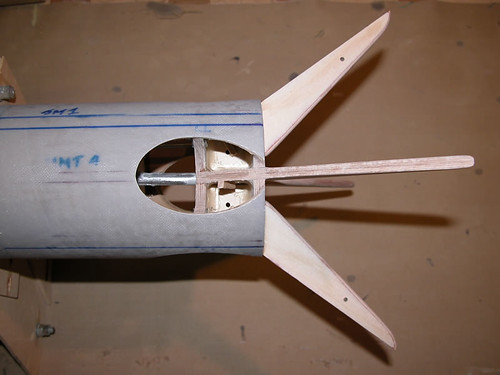
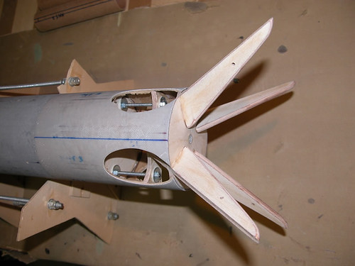
I cut using a Dremel jigsaw after transferring paper templates onto the wood (pics 2-3-4 refer to another project):
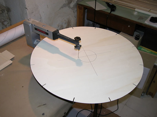
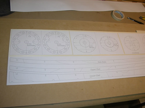
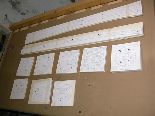
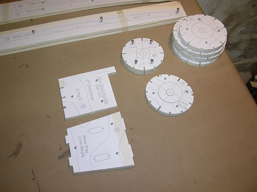
If you refer to the 'flower' style cut inside the 'raped' plug, well, that pattern is the result of freehand routing.
g_boxwood
Well-Known Member
- Joined
- Jan 20, 2009
- Messages
- 564
- Reaction score
- 0
Dave, thank you for pointing out.What was the purpose of glassing the main tubes above the motors? It appears to me that all of the structural stresses are going to be borne by the interal framework. Am I missing something here?
I do personally like painting over fiberglass instead of cardboard. That's why I glass lightly loaded airframes most of the times.
But this is not the case. The motors transfers the thrust loads to the wooden framing and the framing transfers the loads to the a/f tubes that should compress axially. That's what they're meant for and that is what they actually do very well.
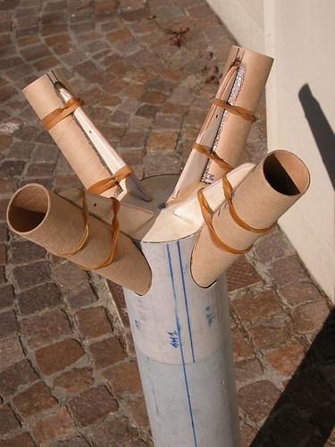
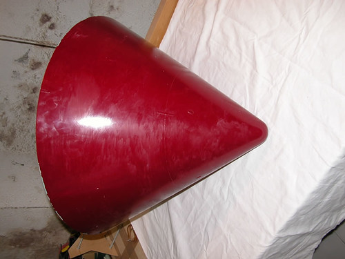
Fact is, PURE axial loads in this case are rather utopistic: both a misfire (worst case) and the little (if any) roll dampening provided by the capsule shape introduce some degree of rolling of the vehicle around the CG (see pic of my other high-drag funnel-like design).

This is what actually causes alternate bending to the rolling frame and requires further reinforcement to the tubes and (most of all) to the couplings.
g_boxwood
Well-Known Member
- Joined
- Jan 20, 2009
- Messages
- 564
- Reaction score
- 0
The process was long and painful and I did not take (m)any pictures.
I felt guilty for the lack of infos about the molding procedure so I added my tech to the Techniques section of the forum:
https://www.rocketryforum.com/showthread.php?t=2607
HTH,
g_boxwood
Well-Known Member
- Joined
- Jan 20, 2009
- Messages
- 564
- Reaction score
- 0
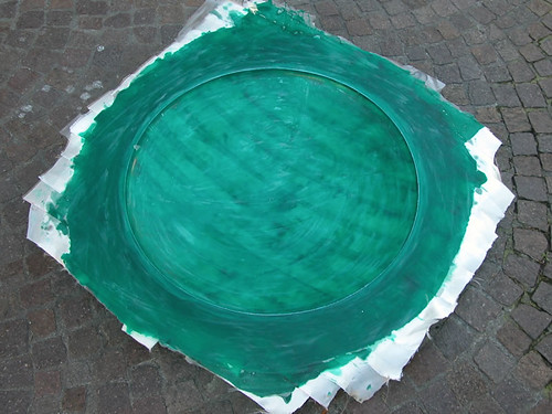
Heatshield Mold
I'm done with it and I found it a lot easier to deal with compared to the command module (CM) mold.
I was able to document it a little better but I will leave the details to the Tech post.
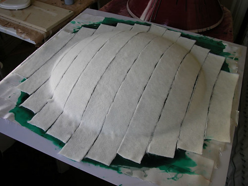
Here is the plug being covered with strips of core material (in the form of 5mm thick absorber):
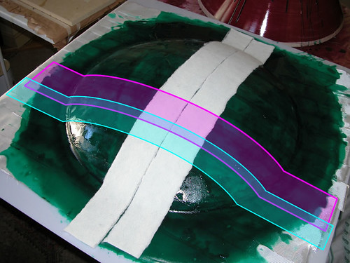
Colored shapes indicate the fiberglass strips pattern underneath the absorber:
. strips are heavy cloth about 3-4" wide
. strips do overlap
. fiberglass strips and absorbers strips are laid across one another
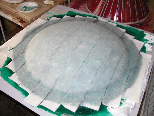
Fully impregnated absorber:
I'm done with it and I found it a lot easier to deal with compared to the command module (CM) mold.
I was able to document it a little better but I will leave the details to the Tech post.
Here is the plug being covered with strips of core material (in the form of 5mm thick absorber):
Colored shapes indicate the fiberglass strips pattern underneath the absorber:
. strips are heavy cloth about 3-4" wide
. strips do overlap
. fiberglass strips and absorbers strips are laid across one another
Fully impregnated absorber:
g_boxwood
Well-Known Member
- Joined
- Jan 20, 2009
- Messages
- 564
- Reaction score
- 0
De-molding was a breeze...
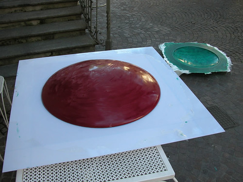
.. and the mold itself turned out great with the only alignment tab detail showing off nicely:

Please remember that the mold finish isn't shining because the PVA film and wax are still in place: I prefer to leave them on until I mold the parts, they act as a protective layer while the molds are set apart.
.. and the mold itself turned out great with the only alignment tab detail showing off nicely:
Please remember that the mold finish isn't shining because the PVA film and wax are still in place: I prefer to leave them on until I mold the parts, they act as a protective layer while the molds are set apart.
g_boxwood
Well-Known Member
- Joined
- Jan 20, 2009
- Messages
- 564
- Reaction score
- 0
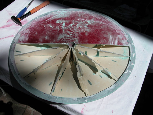
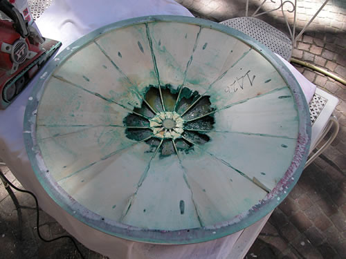
Next came the cruel job again...
The heatshield plug weighted 2560 grams which is too much to make it flyable!
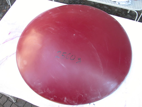
Since it is a big part it needs to do something better than sitting around somewhere... so I wanted to lighten it.
The surgery began...
The heatshield plug weighted 2560 grams which is too much to make it flyable!
Since it is a big part it needs to do something better than sitting around somewhere... so I wanted to lighten it.
The surgery began...
g_boxwood
Well-Known Member
- Joined
- Jan 20, 2009
- Messages
- 564
- Reaction score
- 0
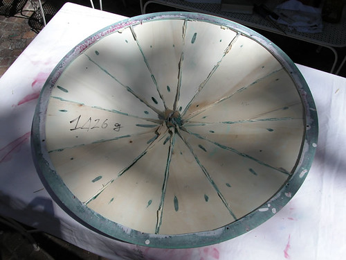
At this point I opted for acetone to melt the foam cores:
Next came grinding and finishing the wooden spiderweb to the final 635 grams!
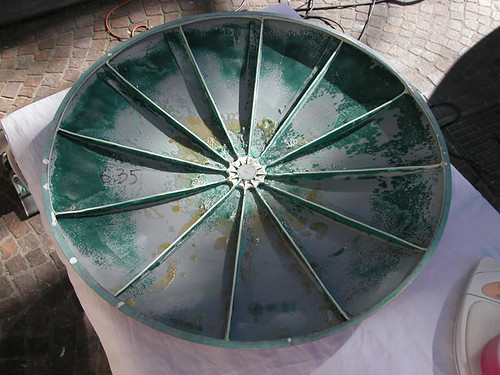
Now, that is too flimsy to fly, I'll add some glass from the inside before joining it to the CM. The final weight will increase but I already saved a lot!
Next came grinding and finishing the wooden spiderweb to the final 635 grams!
Now, that is too flimsy to fly, I'll add some glass from the inside before joining it to the CM. The final weight will increase but I already saved a lot!
MaxQ
Tripoli 2747
And when you finish this beauty...someone can update it...

brianc
Well-Known Member
- Joined
- Jan 17, 2009
- Messages
- 3,242
- Reaction score
- 6
Who's Apollo LES is that?
NASA artist conception of the Orion.
https://rocketry.wordpress.com/2007/05/18/new-ares-orion-images-from-nasa/
GiachiG aka Typico
Well-Known Member
- Joined
- May 4, 2009
- Messages
- 60
- Reaction score
- 0
awesome, as ever...
ben_ullman
Well-Known Member
- Joined
- Jan 17, 2009
- Messages
- 1,523
- Reaction score
- 2
Oh...
That shows you how good of a designer/modeler they are
Ben
g_boxwood
Well-Known Member
- Joined
- Jan 20, 2009
- Messages
- 564
- Reaction score
- 0
Thank you and welcome to TRF dear friend!awesome, as ever...
A lot of work has been done during the past days and that's why I'm not posting...
I want things ready to prime on monday-tuesday weather permitting: I'll get back to you with tons of new pics between the coats while the primer dries...
Reed Goodwin
Well-Known Member
- Joined
- Jan 18, 2009
- Messages
- 2,110
- Reaction score
- 0
Wow, this is a simply AMAZING build! The craftsmanship is superb!
One question: you're making these molds of the parts, but then you say that you're trying to make the plugs flyable. If you're making the plugs flyable, why make the molds? Just so you can reproduce it all later? I'm missing something, aren't I?
Reed
One question: you're making these molds of the parts, but then you say that you're trying to make the plugs flyable. If you're making the plugs flyable, why make the molds? Just so you can reproduce it all later? I'm missing something, aren't I?
Reed
g_boxwood
Well-Known Member
- Joined
- Jan 20, 2009
- Messages
- 564
- Reaction score
- 0
Reed: you're right!
I'll make those parts right out of the mold later on!
The plugs are so big that I want to put them to use instead of having them laying around the workshop with any meaning at all.
The project requires more than one capsule as I won't test everything during the first flight: the plugs are the non-functional capsule, with no internals and no functionality; it won't separate from the tower and it won't come down under its own chutes.
Fact is, making the molds required a lot of work and I wanted to take a pause before committing to the final parts.
Plus, I still have to make up my mind about the capsule internals and how to implement the functional features I desire: in the meantime I want to fly a capsule with little extra work and that's why I opted for the plugs.
Thank you for pointing out! keep questions coming!
g_boxwood
Well-Known Member
- Joined
- Jan 20, 2009
- Messages
- 564
- Reaction score
- 0
Typico, I forgot: why don't you post about your Speedweiser in the HPR section of the Forum?awesome, as ever...
I'm sure people would love it!!!
Similar threads
- Replies
- 2
- Views
- 2K
- Replies
- 5
- Views
- 708