Apollo LES 4"

The Rocketry Forum

Help Support The Rocketry Forum:

This site may earn a commission from merchant affiliate links, including eBay, Amazon, and others.
Thank you guys for the kind words! It's always pleasing to post in here!

I'm feeling way better (I already lost a week...) so tomorrow I'll be able to get back to the sandy part of the job!

@ CharlaineC: you can always give yourself a try at CAD modeling, it isn't that hard and rockets are quite simple objects to start with. I already converted many fellow rocketeers to the ab-use of 3D designing... and I saw it worked for them, as long as you keep it a part-of-the-fun!!!
 
Giacomo,

Absolutely beautiful! Thanks so much for taking the time to repost this and to keep us all informed.

Have you decided yet whether you are modeling PA-1 or PA-2? When you decide let me know and I can forward you all the photos and drawings Gordon and I collected.

In the meantime, here is a link to a short video I did of Gordy and my models.

Giacomo, as always, your work is stunning. Would you do us the favor of posting a link to your group's website. I know it's in Italian but the pictures speak for themselves.

Steve
 
I was finally able to get back to the bench: it took me monday and yesterday to cut the parts for the heatshield frame...

3271221819_e19802a2db.jpg


... and to put them together:

3272042232_efce823b1f.jpg


Today I added the foam blocks:

3271221657_99a860383c.jpg


3271221605_b2ba73797c.jpg


Tomorrow will be a sandy day!
 
Here we go again! Pretty hard-working days!

I started by removing the excess foam just across the vertical members as they provided a sorta guide:

3276133245_47b7385427.jpg


Allt the rest was just a matter of time and patience, I used the rotating spatula as a shaping gauge:

3276952506_11e4f15a0c.jpg


The first epoxy batch was all about filling but I didn't get the result I was expecting...

3276133139_3d5f797bc0.jpg


... and after the glass cloth layer the finish looked 'less' than perfect:

3276952402_f67d1be1e7.jpg
 
I matched the 2 parts together and only 90° out of 360° aligned...

3276132993_74a512903c.jpg


... so the other 270° were shaped in situ with 2-part automotive filler:

3276952236_94b87b84c1.jpg


3276132831_e38c1b65e0.jpg


3276952300_76cff804ac.jpg


Filling ans sanding continues...
 
Going great! This thread is getting better and better every time you post updates.
 
... so the other 270° were shaped in situ with 2-part automotive filler.
Giacomo,

That was one the most difficult details on my build, attaching the poster-board capsule to the fiberglass base. I used a piece of 1" fiberglass tape and epoxy to join the two, then hours of sanding and filling. It was a LOT of work, so I like your solution MUCH better. :)
 
Gus,

in case I was not clear (I didn't tell anything about it) those are the plugs only! if they match NOW the final fiberglass parts will match on their own.

I'll use those plugs to make molds and the molds will then lead to the actual flying parts.

The parts you see right now are rather heavy for flying: I'm considering lightening them once done with the molds (they'll serve nothing from then on) to see if they could be used for flying (I doubt it).
 
Be a lot easier to skip the verticle planes and diagonal plates. Seems like a lot of labor for little benefit. I'd just do the whole bottom in foam and glass it.
 
I spent most of the workshop time filling and sanding the heatshield until I got a tad obsessive with it...

I put it aside for a while and I concentrated on 2 more items I needed: the booster motor transition (BMT) mold and the launch base.

The Booster Motor Transition mold

It is the last mold I need, the easiest and the smallest one. It features 3 centering rings on a 38mm tube and 12 stringers:

3283311697_393d0c55ce.jpg


Note the temporary balsa sticks used to anchor the rubber bands while the aliphatic dries.

The cleaned up frame...

3283311749_bfb411743b.jpg


... is rolled over the glass cloth to find the right skin pattern:

3283311819_eb223ffb37.jpg


The 2 fiberglass layers are then laminated flat and cut to shape before wrapping them around the frame:

3315368357_1c646e81a4.jpg


The joining line is supported with 3/8" balsa sticks to provide a wider mating surface.
 
The Launch Base

I basically got all the infos I needed from the following picture:

2869435719_cdb952d97a.jpg


Some CAD work was necessary to achieve the appropriate design:

3315368799_acd734fa8c.jpg


3315368859_2b5e21096e.jpg


The framing is simple, light and strong, all the members but the diagonal braces are 15 mm dowels, the diagonal braces are 10 mm.

Putting the framing together is pretty simple provided you make some custom jigs to cut all the members to the required length and to the appropriate mating angles!

The base and top hexagons are put together first over the plans: you can't see it but the joint is internally supported by a brass rod.

3315368393_3ed4d28ce8.jpg
 
Last edited:
Next came the mid members, shown here with their cutting and shaping jig:

3316194980_4e6cb28f90.jpg


Mid members as well are supported by a brass rod: the hole is drilled to the appropriate angle using a simple yet effective jig:

3316195030_07a02f5c70.jpg


Mid members provide the first useful link betwen base and top hexagons:

3316195088_43b07b3817.jpg


The following jig was designed to aid in the correct positioning of the hexagons:

3316195298_c8bef18c6a.jpg
 
The jig prooved right and the results are satisying:

3315368669_ca7a8f9e28.jpg


3315368603_8e51acc31b.jpg


3315368643_61cc767be3.jpg


I next added the 6 vertex members:

3315368727_a346d329ee.jpg
 
Giacomo,

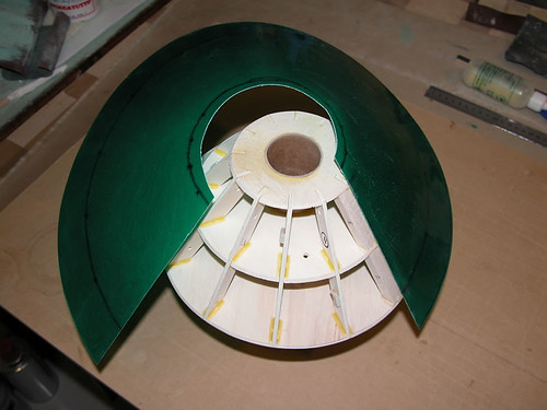
Brilliant, brilliant, brilliant! I love how you did the booster mold transition skin! I wish I had done my capsule skin that way.

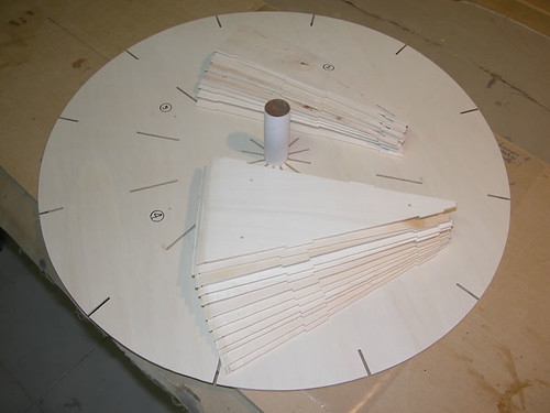
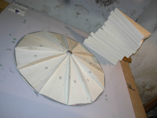
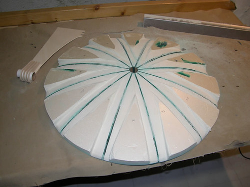
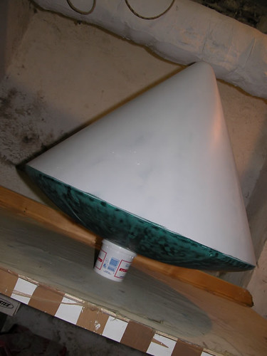
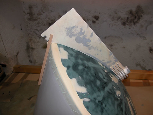
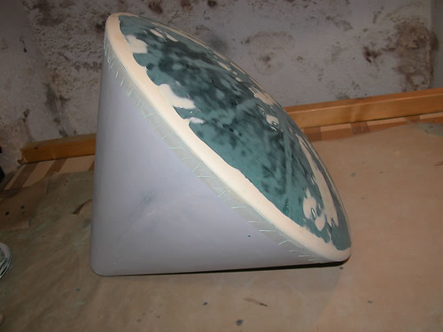
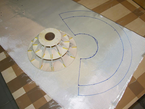
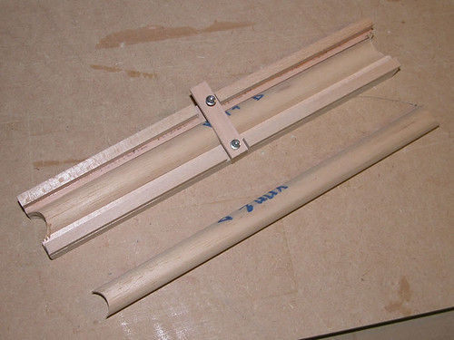
Making the capsule skin was one of the most difficult parts for me. I made mine out of a big piece of posterboard and built it like a transition. I used one of the online programs to figure out the radii and angles and then used a compass and piece of string to draw the arcs. I can't even remember how many pieces I went through just to get one that fit correctly.

It never occurred to me to slowly roll the capsule on the skin material marking as you go. That is SOOOO much easier and smarter. LOL, if I build another now it will take half the time. :) What a great idea!

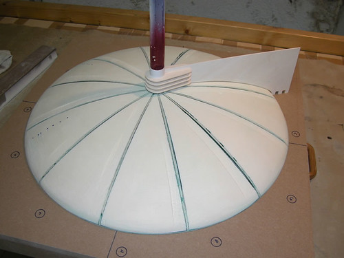
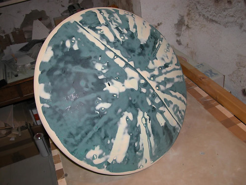
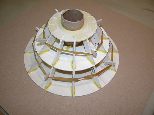
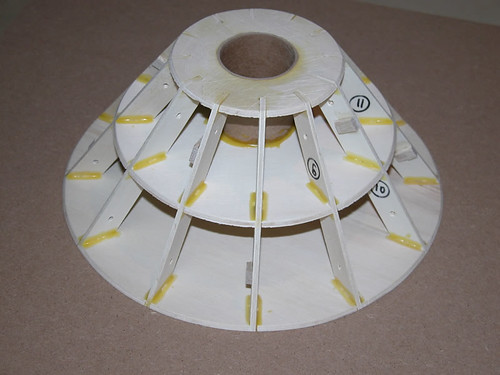
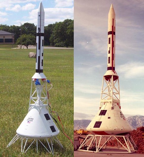
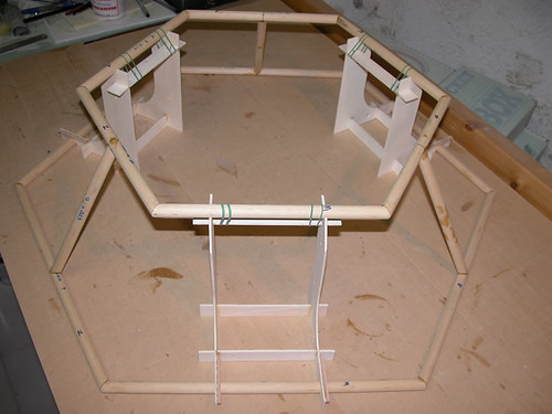
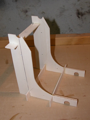
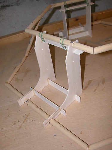
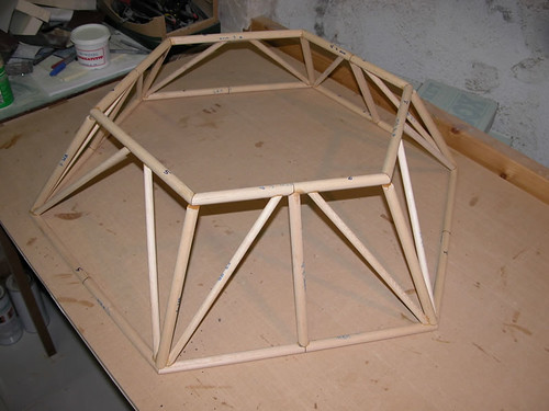
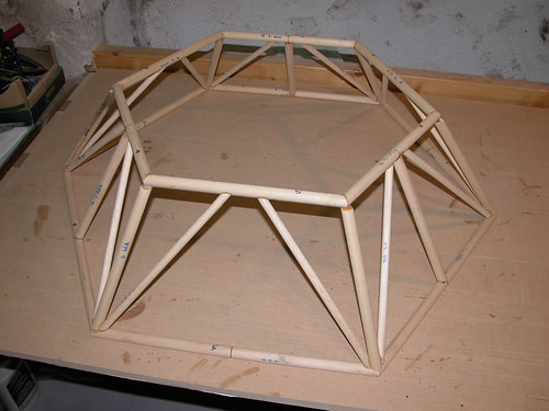
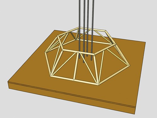
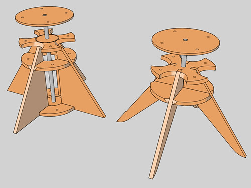
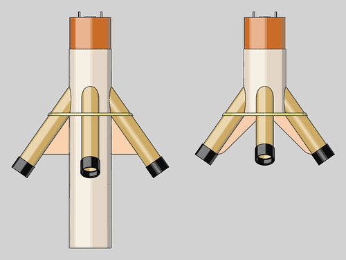
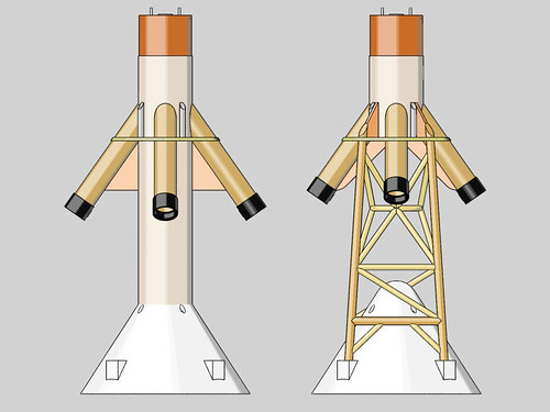
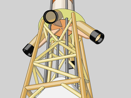
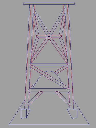
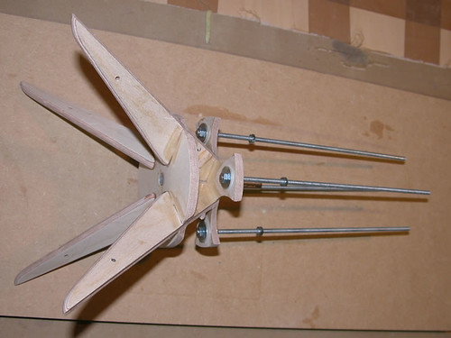
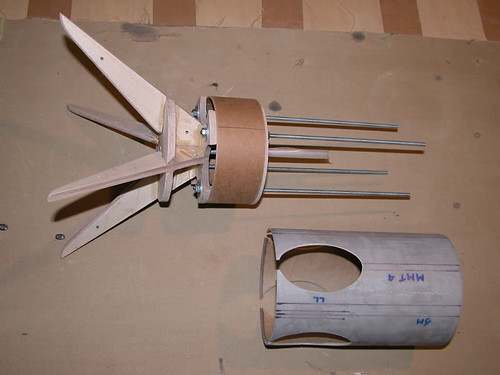
I am really glad to see you are building a launch stand. Not only is it a great display stand, but for launching I just stick a long launch rod in the ground in the inside of the launch stand, slide the model down the rod, and position the launch stand accordingly. I set up the internal launch lug the same distance off center as the outside edge of the escape motor tube. The lug goes from the bottom of the capsule to the top of the capsule, and there are corresponding holes (but no internal tube) in the escape rocket skirt and motor mount base.

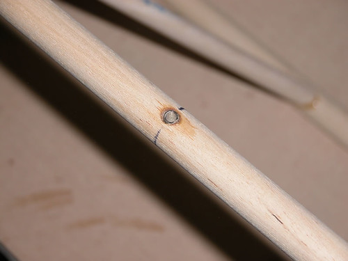
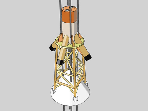
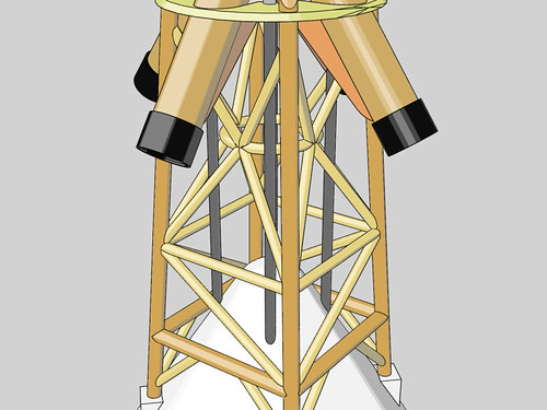
It turns out that this was luckily at just the right spot to miss the tower cross members as the rod passes through.

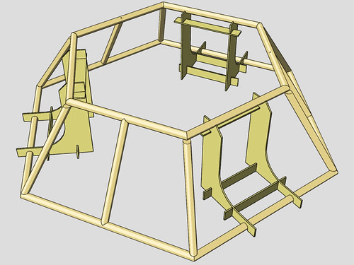
I don't recall seeing in the plans where you are planning to put the launch lugs but this model definitely needs them. Although the real Pad Aborts were launched off the ground without any guide rail, Gordy and I have found these models are extremely prone to weathercocking off the launch pad. Although once it gets up to speed the capsule acts like a cone rocket and self-stabilizes well, right off the launch pad it is going so slowly that the capsule acts more like a parachute. Gordy actually crashed his on its second flight when it went horizontal off the launch pad in fairly breezy conditions. Since then we are REALLY careful to not launch if it's windy.

The video I did of the Pad Abort Project shows this effect very well in the video of the NARAM 50 flight at the end of the video. Watch the smoke trail and you can see how the capsule completely changes direction just a few feet off the pad.

To be honest, I built my model with a 3/16" lug all the way through but the holes are just the tiniest bit off line so a 3/16" rod binds and I end up using a 1/8" rod (4 feet long). The rod is a bit flimsier than what I would prefer but it is definitely necessary. With the HPR motors you are going to need something much more substantial. As with everything in this thread, I will look forward to seeing how you do it.

Giacomo, it is such a treat to watch you build this!
 
Last edited:
Your attention to detail and quality of work are insane! And I mean that in a nice way... :D
 
Gus, Pantherjon and Bruce: thank you!

Gus and aerospike: I'll get back to your infos and comments later on, I'll proceed with the posts first. Thank you for dropping in your lines: every comment, advise and suggestion is much appreciated!

Ok, I left you with the base almost done but for the diagonal braces. In fact, they are the thoughest members to cut and shape but given the right jig they can be done!

The jig is simple and it guides both the cutting and the shaping of both ends; you can see it at the top right corner of the following pic:

3322864940_2aa0613e01.jpg


The degree of cleaness achievable with such a simple tool is enough for the joint:

3322865078_d1eabcefcc.jpg


3322033189_40cfa41b6c.jpg
 
The pad is done, minor work is required to fill some gaps and weather-proof it.

3322033483_6a046dda85.jpg


3322865246_4ea654d74d.jpg


I added some brass inserts to 3 of the 6 horizontal base members: the launch stand will be joined to a MDF base I'll be developing in the future. This way the launch stand will be above the soil and will rest flat on the board: the board will provide a rock-solid anchoring for the launch rods and will avoid warping the stand due to the terrain uneveness.

3322033337_16841e0bbc.jpg


3322945094_8bbf1fc922.jpg
 
Your attention to detail and quality of work are insane! And I mean that in a nice way... :D

Bruce, I finally have found someone who outdoes you ;)

Ben

P.S. but I never finish/paint rockets so my opinion is moot :p
 
Giacomo,

Much to my surprise I just discovered some new details about the structure of the tower of Pad Abort One. I wrote about it in this thread, post #28. The Pad Abort 2 tower looks more similar to the ones used for the manned launches.

With regard to your launch rods, are you using 4 of them as the diagram suggests? That would certainly be much safer for a high power launch than my arrangement.
 

Attachments

  • BP6-Description Manual Diagram pg 26-1.jpg
    BP6-Description Manual Diagram pg 26-1.jpg
    51 KB · Views: 25
Last edited:
New Booster Section

The launch stand 'manifacturing' gave me enough satisfaction to start wondering about a scale tower truss based on the same materials and tooling.

I then played around the CAD a bit to design a new booster section that could deal well with the truss tower:

. here is the new MMT support frame (the first one on the left):

3340920615_cc7a073a2d.jpg


. here is the booster section side-by-side comparison:

3341751604_6d92474f6b.jpg


3340920031_72c2e623e1.jpg


I shortened the MMTs to 3 grain AT casings or Pro38 2G but they still look horrible... that's all I can do @ this scale!
 
The tower truss was slightly modified here and there to fit better and to be a bit easier to be put together.

The tower truss shouldn't interfere with the launch rods: after some tries the clearance was met and the result is clear in the following renderings.

3341751818_7ca4c5d80a.jpg


3341751954_195ab80062.jpg


3340920483_402a0b8752.jpg
 
I shortened the MMTs to 3 grain AT casings or Pro38 2G but they still look horrible... that's all I can do @ this scale!
Giacomo,

I think they look fine. Once you put the skirt on above them they won't be so noticeable.

Your tower truss looks fantastic, especially where the "V-struts" touch the ring. On most models this is really hard to do because of the small size and difficulty in machining but your looks exactly like the real thing. I don't know if folks realize how hard that is to do. Again, really amazing.

The most critical point on these whole models is where the tower attaches to the motor mount. These 4 attachment points need to be extremely strong but, because of the angle of the skirt, there is VERY little room to work with to attach the tops of the tower legs to the motor mount plate. I created flanges on mine to help (photo below) because my plate was made out of foam board. Gordy used hollow carbon fiber tubes for the legs of his tower so he ran kevlar through the tubes and up over the motor mount to help secure it.

On the real skirt there were support pieces which ran over the skirt to the escape motor housing (see pic) which may be useful in a high power version.

6.jpg

Apollo7LESSkirt.jpg
 
The most critical point on these whole models is where the tower attaches to the motor mount.
Gus, you got it! That's where I cheated...

Basically I narrowed the top of the truss to leave some more wood on the outside of the tubes.

3344841620_49fb6b998e.jpg
 
Ok, after the virtual tweaking the real work began:

. here are the pieces for the new MMTs support

3341752618_913d0255ff.jpg


. put together

3341752686_f4cf4943cb.jpg


3341752756_a93f292063.jpg


. ready for insertion into the shorter booster section

3340919791_e19fb7f63d.jpg
 
Back
Top