75mm MD L3 Build

The Rocketry Forum

Help Support The Rocketry Forum:

This site may earn a commission from merchant affiliate links, including eBay, Amazon, and others.

caruolo

Well-Known Member
Joined
Jan 27, 2015
Messages
68
Reaction score
0
Hey everyone,

Haha I was a bit late on my build thread for my L2, as I am again for my L3.... Been busy with school and work so I haven't had much spare time, but we're coming up to my launch date, BALLS 25, and I was thinking I might as well write something up on TRF before I finalize the build.

As for that, when thinking about my L3, I wanted to push my envelope of experience and after considering my L2 with a Hyperloc 1600, I chose to do a 75mm MD bird. The idea is to fly it with a baby M to between 20-25k (I've flown to 18k on a J1000 at mach 3, so its a familiar process), and in a subsequent flight, stick 10,000 Ns motor and hope for the best to around 45k. The flight motor, an AeroTech M1350 DMS, is about 1/3 the length of the rocket, while the full sized motor is about 2/3 of the length.

But back to the cert flight. I consulted two TRA TAPS, and sent in a preliminary report detailing my plan, which they O.K'd several months ago. Since then, I have been slowly building, time permitting. The goals of the bird, named KNOOP MK III (L1 was MK I, etc) are as follows:

-Reach above 20,000' on baby M DMS cert. motor
-Integrate rapid prototyping
-Integrated Camera, separate of Av-Bay
-Vehicle for subsequent high altitude attempts

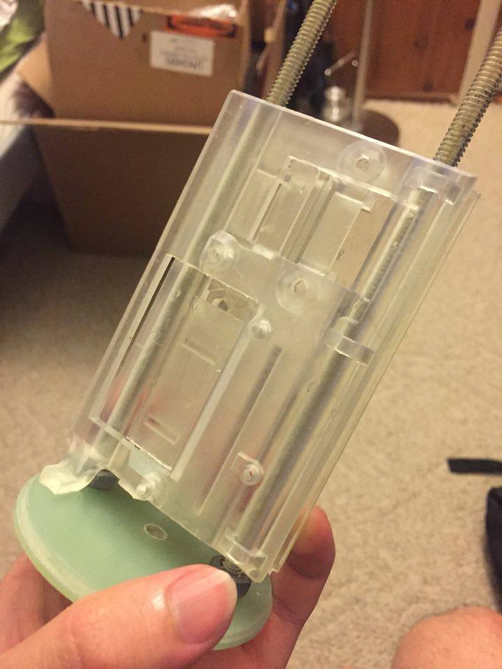
The rapid prototyping section involves 3D printing the electronics sled, camera mount, and tail-cone. I have access to several Form 2 SLA 3D printers at work, so the detail and accuracy on these parts is quite high. The sled integrated cuts that takes the shape of nuts. I decided to make the camera bay separate from the Av-bay because of the chance of engaging the flight computers early during mach transition. I will also be using surgical tubing as my charge container to practice for high altitude flights.

The following is a list of major components:
-RW (Madcow) FW 5.6:1 VK Nosecone
-60" Standard FW Airframe
-1/8" G10 fins w/ 4 layers of increasing and 0,30,45,90 direction 2x2 Twill carbon T2T utilizing Aeropoxy PR2032 w/ PH3660
-Cotronics 940SS Ceramic Adhesive on Leading Edge
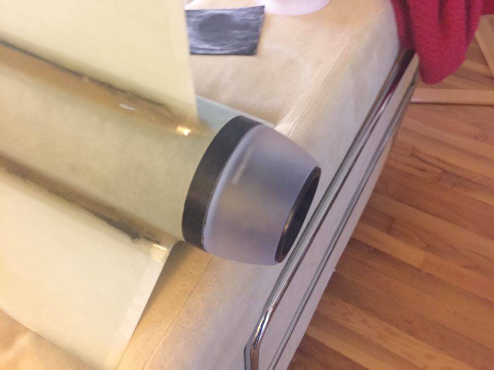
-3D printed Tailcone
-Solidworks designed and 3D printed Sled and Camera Mount
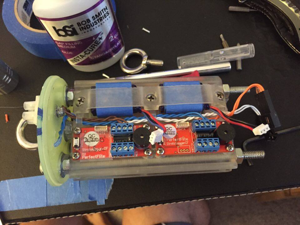
-Nosecone coupler as Av-bay w/ the following: Beeline 100mW GPS, 2x Stratologger CF (Redundant), 1x Raven 3 (Accelerometer data acquisition), and related batteries
-25' 1" flat kevlar "drogue"
-Iris Ultra Fruity Chute w/ 20' Teddy Kevlar Cord Main

Now for pics and the build.


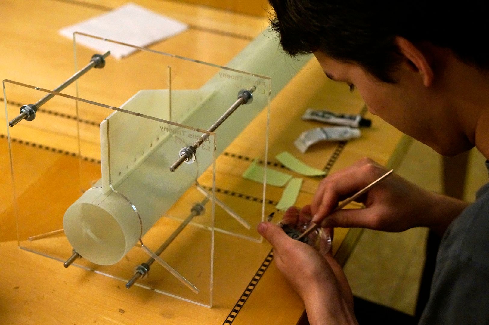
Here I am JB-Weld tacking the fins on using a laser cut acrylic jig that I made at TechShop. I then Used a micrometer to ensure the spacing between the sheets of acrylic were even to prevent distortion between plates. All surfaces were prepped properly during this build before adhesives were applied (I.E washed with soap and water, scuffed up with 100 grit sandpaper, soap and water again, and finally 2x acetone wipe using fiber free cloth).


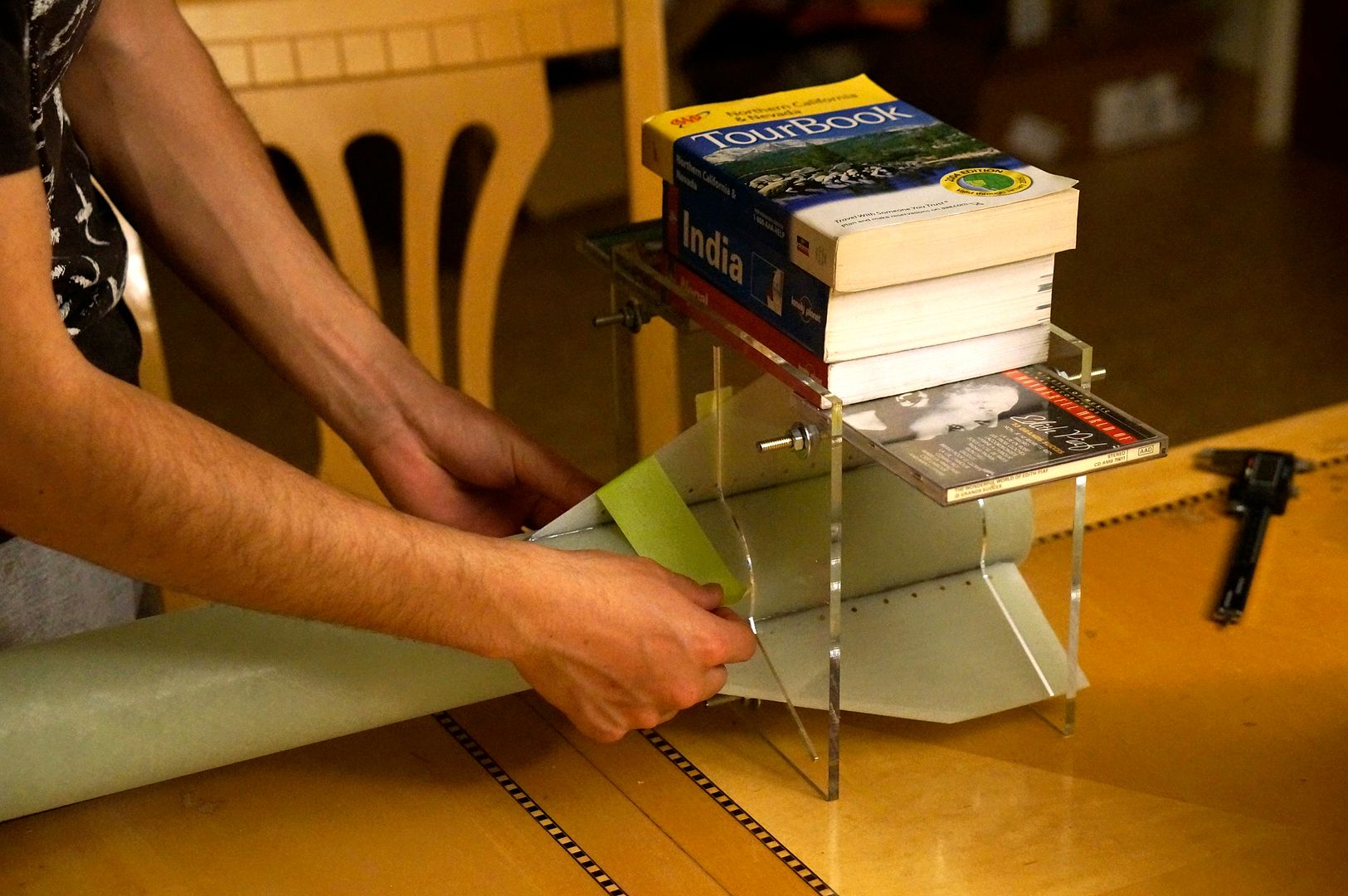
Once the fin was in place with the JB Weld, I used a few books and a piece of tape to ensure proper contact with the airframe's surface.


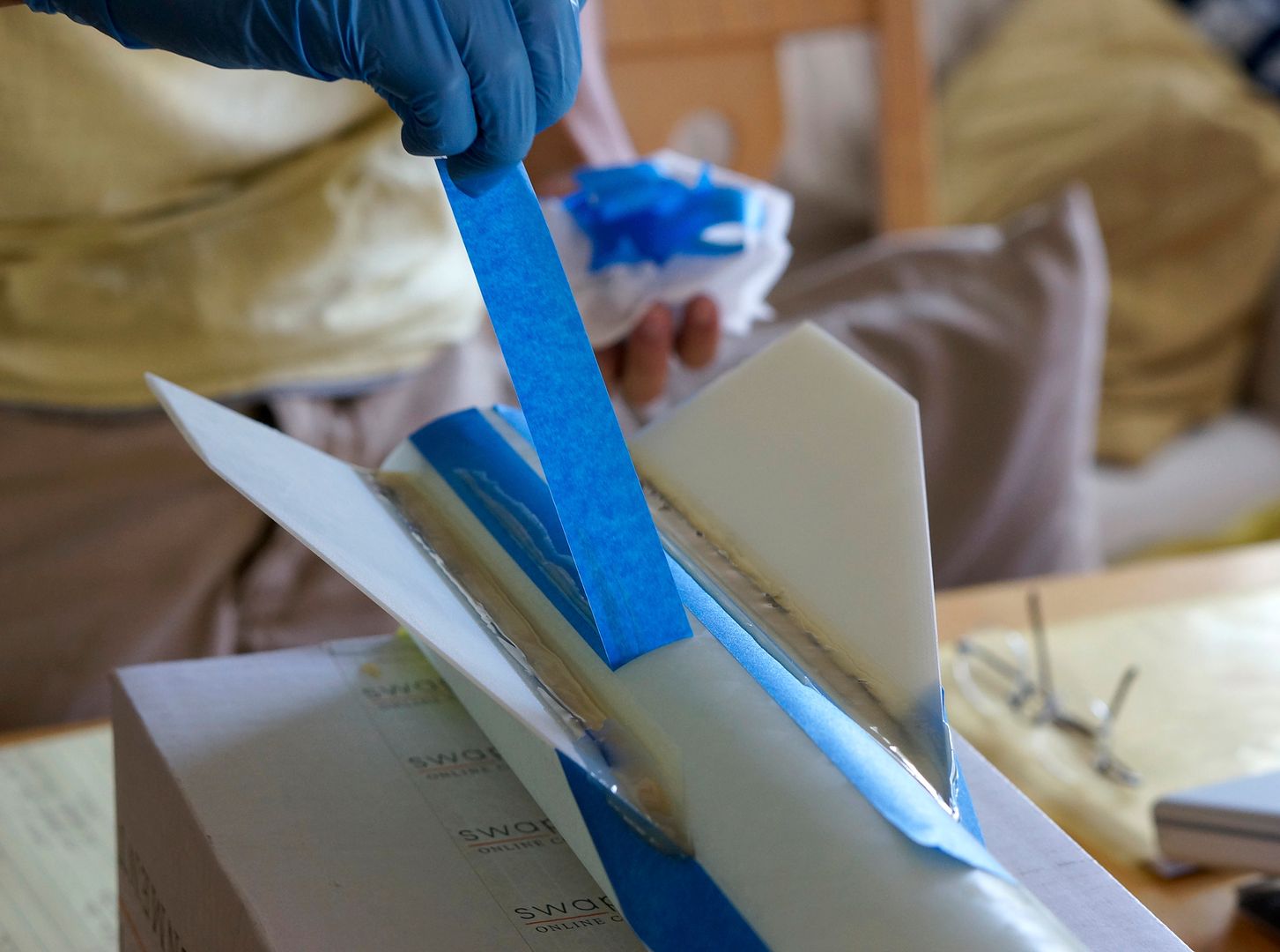
Here I am removing the tape from the fillets (Aeropoxy ES6209) which were done on-top of weaving carbon fiber tow between the holes seen.


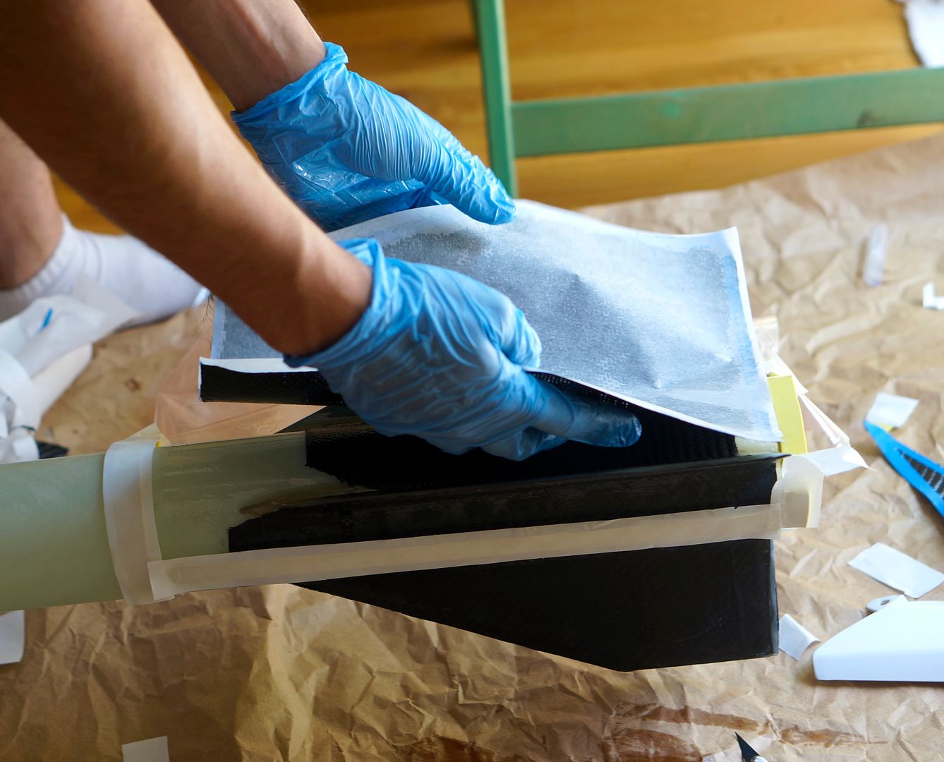
This is the final layer of one of the sides of the T2T being applied. I first wetted out each layer on Wax paper, which sat on a piece of glass and then cut it out to the right size and simply folded the wax paper w/ wet fabric over the fins.


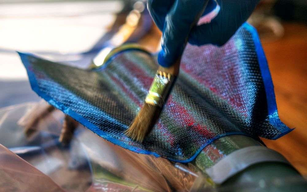
Ensuring proper saturation on the top layer before vacuum bagging.


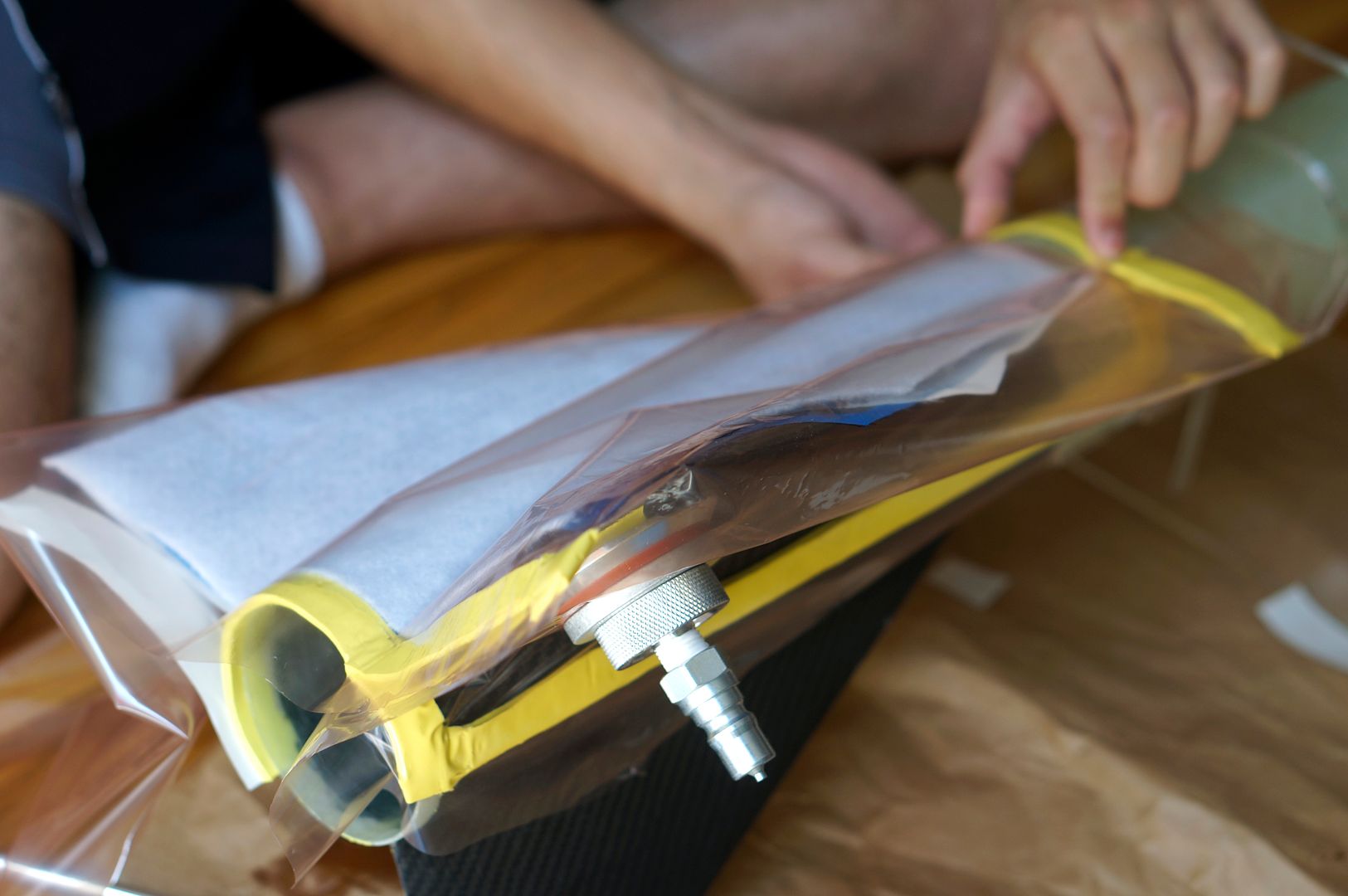
Wrapping vacuum bag around fin w/ proper pleats and seals.


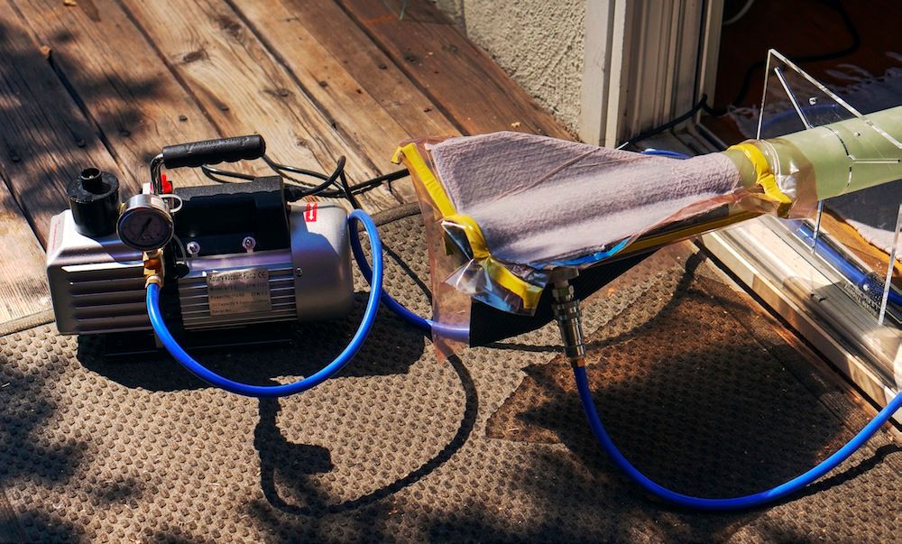
Pulled max vacuum using 2 stage rotary pump for 1.5 hours in the sun, and then shut off pump.


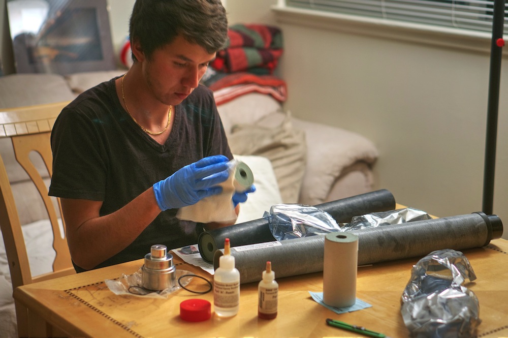
I decided to build the motor in advance because of wanting a full cure on the epoxy, so I began with wiping down the outsides of the grains that had slight smudges of propellant on them.


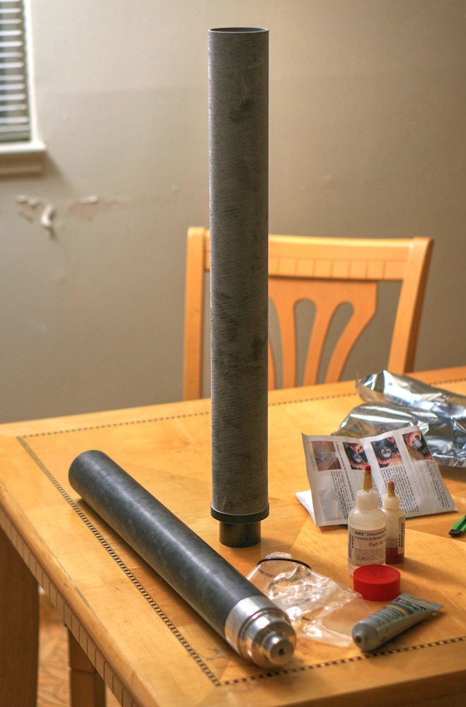
Here is the liner standing with all the oring spaces and grains inserted.


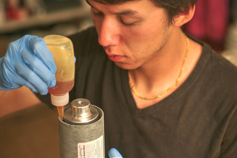
Filling Bulkhead/casing gap with the supplied epoxy. Followed each step precisely throughout the motor assembly process.


Here I am designing the sled w/ the 3 flight computers and GPS unit.


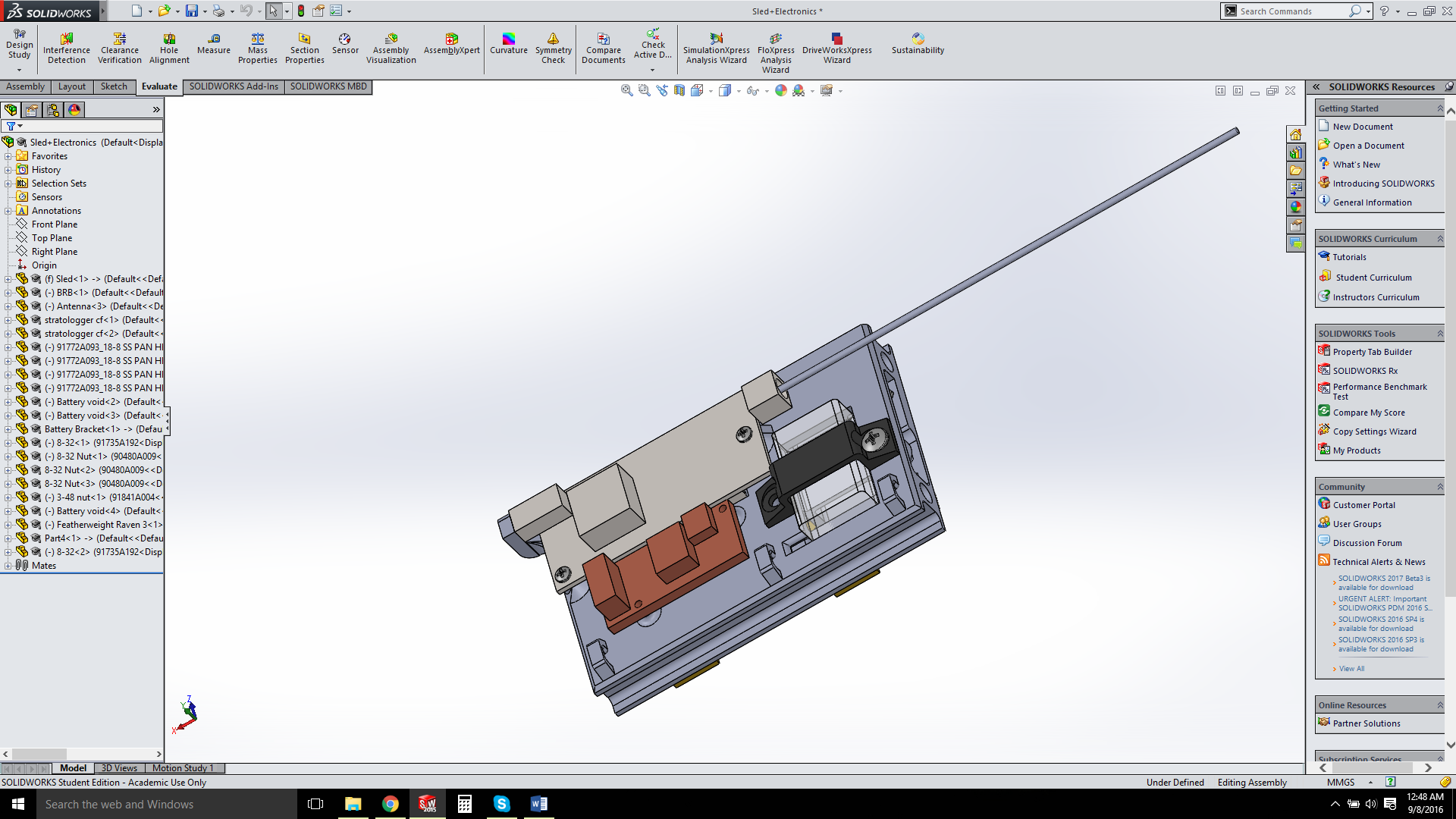
Beeline GPS and Raven 3 Flight Computer.
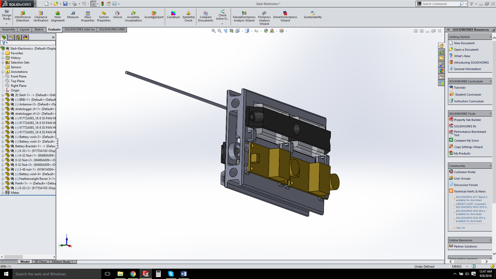


2x Stratologger CF


That about concludes what I have done to this point. At the moment I am printing said sled, and machining the motor retainer to accept 1/4 all threads that will pass through the camera mount.

Comments and suggestions are welcome!

Thanks!
 
Last edited:
Forgot to mention, there are no buttons/lugs as this will be launched out of a tower.

And here's a photo of the SLA printed sled. It turned out wonderfully!

 
Excellent man! Especially because of the large pics! I do not understand English well but pics immediately understand! You gave me some ideas for making fins :)All have phones but not photographed. They prefer to come across as Mark Twain without having his talent :)
 
Last edited:
Are those holes spanning the root of the fins? I had considered trying this, but hadn't really seen much use of it on here, and I wasn't sure if it would compromise the fin in any way. Did you do FEA in solidworks to figure out how far apart to put them or how far from the root to put them?

Thanks!

Brian
 
The M1350 requires 24 hours of epoxy cure which, provided the TAPs are on board, almost always means they will not witness assembly if you're only really seeing them on the day of the launch. Mine were cool with it.
 
Elegant work. I'm really interested to see the 3D printed tailcone that you mentioned in the intro.
 
The M1350 requires 24 hours of epoxy cure which, provided the TAPs are on board, almost always means they will not witness assembly if you're only really seeing them on the day of the launch. Mine were cool with it.

If you think about it TAPs really only get to see pictures of the build process anyway, seems like motor assembly would be OK with most too. In fact, come to think about it, my full L3 flight was only seen on video by one of my TAPs (although the other watched closely).
 
My bad. I don't use AT motors. Then, why is this a DMS and not an LMS? I thought LMS was "load it, fly it, throw it away," and DMS was "fly it, throw it away."

Not sure why they call it a DMS when it is actually like the LMS motors, prossibly the are cutting down the different nomeclatures they use. Technically a LMS is a DMS. 🤔
 
Are those holes spanning the root of the fins? I had considered trying this, but hadn't really seen much use of it on here, and I wasn't sure if it would compromise the fin in any way. Did you do FEA in solidworks to figure out how far apart to put them or how far from the root to put them?

Thanks!

Brian

I was thinking about doing FEA, but got a bit lazy and sort of just went with it LOL I know, not very technical, but I had heard of other people doing it and wanted to give it a try. I think that what I could have done better with it is woven more tow back and forth than what I did.

Elegant work. I'm really interested to see the 3D printed tailcone that you mentioned in the intro.

Here's a photo of it sitting on the nozzle of the motor. I am planning on either JB welding it on, or using the 940SS ceramic adhesive I have. I know that there's a high chance it melts on the way up, but its just a trial concept, so we'll see how it goes!


I hope you got one of the $300 ones and did not have to pay $400!

Haha, I think I paid around ~$360? Still cheaper than buying the hardware for an RMS :)


Thank you everyone for the kind words, I really appreciate it!
 
I presume a 70cm band Beeline GPS or is that the 33cm (900Mhz) tracker? Is your antenna going to be facing aft out of the nosecone bulkhead projecting into the chute bay? Are you doing dual deploy from nosecone mounted electronics with a cutter to unfurl a restrained main chute?

Is the tracker riding with the altimeters? If so, I presume you know you could be hamstringing your tracker range by having the antenna paralleling the all-thread. That's why I mentioned an aft-facing antenna through or out of the bulkhead or a situation where the antenna is not in parallel to the all thread. You mentioned Mach 3 with J's so I think you've had experience with the tracker already. That's good.

I know the Raven is resistant to Rf at least with the low powered Beeline GPS units. They can ride next to each other and be happy. I don't know about the Stratologgers.

As high as you plan on flying this thing, you'll want to eek out as much range as you can from the Beeline GPS installation.

What kind of nosecone? I tried to look it up on the Madcow site but couldn't find it. I'd suggest you stick with the white fiberglass or any other color except black. A person has posted that he put a tracker in a Profusion black nosecone and the Rf was attenuated drastically. Even though it's not "carbon fiber" some lampblack or something like it is used to get it black. Others say they have no trouble with Profusion nosecones but I'd do a range test in the air and on the ground just the same. I'll hoist a nosecone up in the air in a tree to simulate a descending rocket and if I get a pretty good range cognizant of the surrounding obstructions, I'll call it good. Also I lay the nosecone on the ground and see what the ground footprint is. You can do the test with your bare tracker and see if there are disparities. If there are, you'll have to decide whether or not you can live with them or not. I have a 4 inch diameter Profusion nosecone with a sled for a low powered Beeline GPS 70cm tracker.
I found this out and modified it for the 100Mw model. I spent too much time on the nosecone to ditch it for another. Am going to do a range test exercise on it and use Rf resistant deployment electronics in a lower, separate bay on a conventional
dual deploy rocket.

Do not use metallic paint on a rocket bay that contains a buried tracker/antenna. Very bad mojo if no signals are received after your expected apogee or you try a range check on your prettily painted rocket and find out
your receiver can't hear squat. Been there. Done that. Don't repeat my mistakes. They'll be folks who post they fly Profusion with trackers inside and use metallic paint but the attenuation can be frequency and power
dependent. If you want the chance to avoid any of these problems, these rules of thumb are very valid.

Last test: Put restrained ematches on all the circuits, fire up the tracker have it sending out the GPS packets (if APRS) every 5 seconds, turn on the deployment devices and let the rocket sit for an hour. If the matches don't fire
or the altimeters don't reset and go silent, you'll stand a good chance the devices will perform as needed. If you've already proven to yourself beyond doubt that your electronics play well with your high powered Beeline GPS, you can skip this step.

Best of luck on this grand attempt. Looks really cool to me. Kurt Savegnago
 
Last edited:
Any chance you could email me that .sldprt/.sldasm file? I'd like to play around with it for my altimeter bay. Email is bass matt f at gmail dot com (no spaces). Funny enough, I actually have the same set of calipers as you. :)
 
I presume a 70cm band Beeline GPS or is that the 33cm (900Mhz) tracker? Is your antenna going to be facing aft out of the nosecone bulkhead projecting into the chute bay? Are you doing dual deploy from nosecone mounted electronics with a cutter to unfurl a restrained main chute?

Is the tracker riding with the altimeters? If so, I presume you know you could be hamstringing your tracker range by having the antenna paralleling the all-thread. That's why I mentioned an aft-facing antenna through or out of the bulkhead or a situation where the antenna is not in parallel to the all thread. You mentioned Mach 3 with J's so I think you've had experience with the tracker already. That's good.

I know the Raven is resistant to Rf at least with the low powered Beeline GPS units. They can ride next to each other and be happy. I don't know about the Stratologgers.

As high as you plan on flying this thing, you'll want to eek out as much range as you can from the Beeline GPS installation.

What kind of nosecone? I tried to look it up on the Madcow site but couldn't find it. I'd suggest you stick with the white fiberglass or any other color except black. A person has posted that he put a tracker in a Profusion black nosecone and the Rf was attenuated drastically. Even though it's not "carbon fiber" some lampblack or something like it is used to get it black. Others say they have no trouble with Profusion nosecones but I'd do a range test in the air and on the ground just the same. I'll hoist a nosecone up in the air in a tree to simulate a descending rocket and if I get a pretty good range cognizant of the surrounding obstructions, I'll call it good. Also I lay the nosecone on the ground and see what the ground footprint is. You can do the test with your bare tracker and see if there are disparities. If there are, you'll have to decide whether or not you can live with them or not. I have a 4 inch diameter Profusion nosecone with a sled for a low powered Beeline GPS 70cm tracker.
I found this out and modified it for the 100Mw model. I spent too much time on the nosecone to ditch it for another. Am going to do a range test exercise on it and use Rf resistant deployment electronics in a lower, separate bay on a conventional
dual deploy rocket.

Do not use metallic paint on a rocket bay that contains a buried tracker/antenna. Very bad mojo if no signals are received after your expected apogee or you try a range check on your prettily painted rocket and find out
your receiver can't hear squat. Been there. Done that. Don't repeat my mistakes. They'll be folks who post they fly Profusion with trackers inside and use metallic paint but the attenuation can be frequency and power
dependent. If you want the chance to avoid any of these problems, these rules of thumb are very valid.

Last test: Put restrained ematches on all the circuits, fire up the tracker have it sending out the GPS packets (if APRS) every 5 seconds, turn on the deployment devices and let the rocket sit for an hour. If the matches don't fire
or the altimeters don't reset and go silent, you'll stand a good chance the devices will perform as needed. If you've already proven to yourself beyond doubt that your electronics play well with your high powered Beeline GPS, you can skip this step.

Best of luck on this grand attempt. Looks really cool to me. Kurt Savegnago

Its a 70cm 100mW Beeline. The drogue cord comes out between the airframe and avbay, while the main ejects from the nosecone. The antenna is also located in the nosecone (protrudes out from the bulkhead of the av-bay. The 38mm high mach flight had very similar setup and I had a lock the entire time on 3 flights. The 38mm integrated a stratologger as the flight computer, and it worked perfectly well so I'm not worried about the GPS interfering.

The nosecone is a standard walled FW 5.6:1 VK cone. I know about transmission attenuation, which was why I did not go with a carbon fiber airframe/nosecone. I am not planning on painting the rocket, rather polishing the bare FW surface with epoxy/finesse it II.

Thanks for the tips!

You are all set then! Have a great flight. Kurt
 
I have been working on the avbay and motor retainer (camera mount above it).

Here's what the avbay looks like right now. I'm not sure how to connect the battery/charge it because its some proprietary mini connector.

Anyone have ideas on that?

 
From the pic, it looks like a JST-XH balance plug for a 2 cell lipo. There are a number of chargers that will work with it directly. You can also get extension leads for them. I would get the mating socket for it, and connect just the 2 outside wires for your altimeters. That should be the full pack voltage.
 
From the pic, it looks like a JST-XH balance plug for a 2 cell lipo. There are a number of chargers that will work with it directly. You can also get extension leads for them. I would get the mating socket for it, and connect just the 2 outside wires for your altimeters. That should be the full pack voltage.

Is that the standard lipo connector? I have a lipo charger with standard sockets, and it doesnt fit that one.

Here's the link to the battery:
https://www.hobbyking.com/hobbyking/store/uh_viewItem.asp?idProduct=19423
 
Ahh, no. That battery has the proprietary e-flite connector. What I would do, is get 2 of these..

https://m.ebay.com/itm/1-JST-JST-XH-2S-Balance-Wire-Extension-Adapter-20CM-/230476270104

Hobbyking shows them out of stock. Cut the extension in half, use one end as an adapter to the altimeter. The other, cut the battery wires and solder the wires together. When doing this, cut one battery wire at a time, solder and heatshrink. That will prevent any shorts.

Another option is to do that for the balance lead, and pull another wire pair out to a stronger connector like deans, XT30, or XT60. Those balance plugs aren't super secure. They will work if you keep flight stress off them though.
 
Last edited:
Chop those and get a couple male/female sets of whatever you want to use. JST or standard JR servo plugs work great, and you can get connector locks for the standard JR plugs.
 
Back
Top