I have had success with rail guides on a resin printer, but I have never been happy with the quality on a FDM printer. I have just had terrible results with printing supports and the overhangs are terrible. Does anyone have any other results?
You are using an out of date browser. It may not display this or other websites correctly.
You should upgrade or use an alternative browser.
You should upgrade or use an alternative browser.
3D Printing 3D Printed Rail Guides
- Thread starter cwbullet
- Start date


Help Support The Rocketry Forum:
This site may earn a commission from merchant affiliate
links, including eBay, Amazon, and others.
Neutronium95
Well-Known Member
- Joined
- Jan 17, 2010
- Messages
- 1,075
- Reaction score
- 1,563
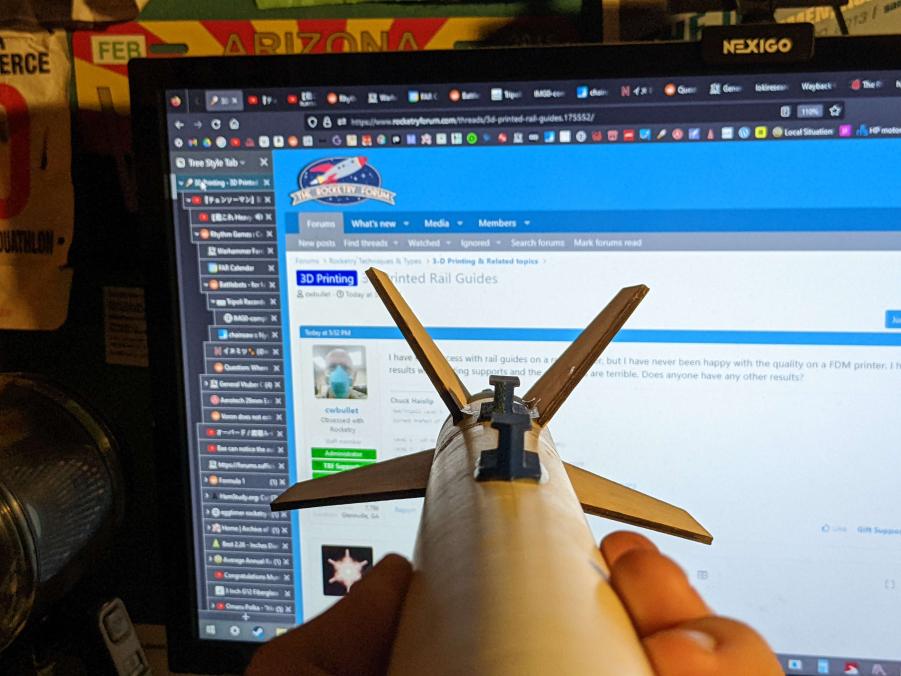
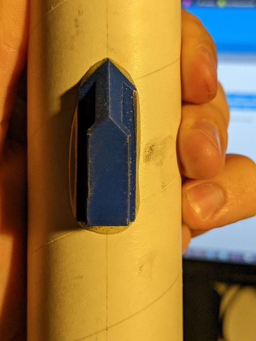
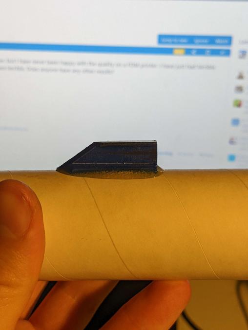
As a last minute solution to allow it to fly at clubs without a micro rail, I designed and printed these 1010 conformal rail guides for the rocket. I printed them with the flat aft end on the bed, so they didn't require any support material. I blindly copied dimensions from a friend for the actual rail guide part, so they ended up a bit too tall, but they work fine. The pointed tips are mostly there to make alignment easy, you just have to get them on the same line. I printed them in Esun PLA+ on an Elegoo Neptune 2, and they've worked great so far for multiple flights on punchy G motors.
Those are easy to print. I should have been more specific. I have trouble printing the round ones.
Kelly
Usually remembers to get the pointy end up
Buttons? Hmm I've never had issues, printing with PETG, and I don't even remember using supports. Somehow they just worked. If supports is the issue, why not design one with the steepest possible overhang? If you can get 60° that should work fine.
I might try that. Thanks. 90 degrees is just not working for me.Buttons? Hmm I've never had issues, printing with PETG, and I don't even remember using supports. Somehow they just worked. If supports is the issue, why not design one with the steepest possible overhang? If you can get 60° that should work fine.
I have done 20mm and Makerbeam as well as 1010 rail buttons / lugs... They have worked well for my low-powered rockets. They squeak and catch a bit when I am manually moving the rocket on the rail but they seem to let the rockets move freely when under their own launch power.
I think the secret is orienting them 90 degrees so that the layers and lines go from mounting point, up central post support, and though button - like Neutron95 shared.
I just flatten the back and print with a brim (also try to mount these in 3D printed parts)...

I think the secret is orienting them 90 degrees so that the layers and lines go from mounting point, up central post support, and though button - like Neutron95 shared.
I just flatten the back and print with a brim (also try to mount these in 3D printed parts)...
- Joined
- Jun 4, 2018
- Messages
- 1,287
- Reaction score
- 924
I printed some for my Estes Saturn V build in PETG, they were printed vertical so that layers are perpendicular to the body tube. Worked fine for that build.
EDIT: Not sure why I did not see my other post above when I replied but sorry for the redundant post.
Chuck -- If I am doing a button I print it vertical and flatten the rear side some to eliminate need for supports.

I have had success with rail guides on a resin printer, but I have never been happy with the quality on a FDM printer. I have just had terrible results with printing supports and the overhangs are terrible. Does anyone have any other results?
Chuck -- If I am doing a button I print it vertical and flatten the rear side some to eliminate need for supports.
Last edited:
- Joined
- Apr 13, 2013
- Messages
- 2,435
- Reaction score
- 1,342
Printing this way should also avoid the issues with the Z-axis being weaker.
I have done 20mm and Makerbeam as well as 1010 rail buttons / lugs... They have worked well for my low-powered rockets. They squeak and catch a bit when I am manually moving the rocket on the rail but they seem to let the rockets move freely when under their own launch power.
I think the secret is orienting them 90 degrees so that the layers and lines go from mounting point, up central post support, and though button - like Neutron95 shared.
I just flatten the back and print with a brim (also try to mount these in 3D printed parts)...
View attachment 545709
This is similar to what I do. I have given up on the round ones.
- Joined
- Mar 27, 2011
- Messages
- 1,156
- Reaction score
- 569

- Joined
- May 31, 2011
- Messages
- 333
- Reaction score
- 132
I have designed a number of rail guides.
You can check them out here and download them for free.
https://www.thingiverse.com/jackhydrazine/designs
You can check them out here and download them for free.
https://www.thingiverse.com/jackhydrazine/designs
This thread makes me wonder if we need to be training our RSOs to look for which way the layers have been printed. A rocket on the rail which breaks loose as soon as the motor lights could be a real hazard. It would tend to fall away from the rail. Rockets are almost always placed on the rail with the rail behind the rocket (farther from the flight line), so falling away from the rail means it's starting to aim towards the crowd. That's about as bad as it can get.
This thread makes me wonder if we need to be training our RSOs to look for which way the layers have been printed. A rocket on the rail which breaks loose as soon as the motor lights could be a real hazard. It would tend to fall away from the rail. Rockets are almost always placed on the rail with the rail behind the rocket (farther from the flight line), so falling away from the rail means it's starting to aim towards the crowd. That's about as bad as it can get.
If the RSOs are checking rocket viability they should definitely be familiar with 3D printing technology (at least enough to ask the right questions) since this is becoming more and more common for a variety of parts. The z-axis weakness can also affect fins that are printed vertically as well as other parts printed in convenient but weaker orientations. Even an experienced rocketeer who is just getting started w/ 3D printing could overlook something fundamental (like using PLA or another low-temperature plastic for motor mounts or retainer caps/blocks).
caveduck
semi old rocketeer
- Joined
- Jun 6, 2011
- Messages
- 1,827
- Reaction score
- 585
I've used Jack's designs (thanks for contributing those!) with great success, printing them FDM vertically in PETG, plated up to do 15 or 20 in one go overnight. Never had one break in either axis. They give you plenty of gluing area and a bit of grip texture to boot. If I really want round ones I just use the ones from rail-buttons.com which are very inexpensive, or occasionally machine my own taller ones out of Delrin (acetal) for special situations. That said, I probably wouldn't use printed guides on a 50kg rocket.
I've used Jack's designs (thanks for contributing those!) with great success, printing them FDM vertically in PETG, plated up to do 15 or 20 in one go overnight. Never had one break in either axis. They give you plenty of gluing area and a bit of grip texture to boot. If I really want round ones I just use the ones from rail-buttons.com which are very inexpensive, or occasionally machine my own taller ones out of Delrin (acetal) for special situations. That said, I probably wouldn't use printed guides on a 50kg rocket.
Can you post an image of your print orientation?

That is how I print those, too, thanks. The round ones are the ones I am having difficulty printing.Here's how I set them up - 100% infill, supports enabled, so the printing plane is perpendicular to the long axis of the rail guide. The MK3S will print 5/hr; the supports only add ~8 mins.
View attachment 560827
I think you’re making the same point I am: how do we train our RSOs (and Prefects, TAPs, and Directors for that matter) for what to look for when evaluating rockets with 3D printed components. The fact remains that most of us still don’t have much (if any) experience or knowledge in evaluating potential failure modes of 3D printed parts. It would be great if those who are spearheading the technology would put some training materials together that we could share with everyone who might need it. That would lead to faster acceptance of 3D printed components.If the RSOs are checking rocket viability they should definitely be familiar with 3D printing technology (at least enough to ask the right questions) since this is becoming more and more common for a variety of parts. The z-axis weakness can also affect fins that are printed vertically as well as other parts printed in convenient but weaker orientations. Even an experienced rocketeer who is just getting started w/ 3D printing could overlook something fundamental (like using PLA or another low-temperature plastic for motor mounts or retainer caps/blocks).
I think you’re making the same point I am: how do we train our RSOs (and Prefects, TAPs, and Directors for that matter) for what to look for when evaluating rockets with 3D printed components. The fact remains that most of us still don’t have much (if any) experience or knowledge in evaluating potential failure modes of 3D printed parts. It would be great if those who are spearheading the technology would put some training materials together that we could share with everyone who might need it. That would lead to faster acceptance of 3D printed components.
I will think about this one. I think the key is asking the right questions.
Low power really does not matter what they are built with (sort of).
Mid and high-power success depends on the following:
- The material used (PETG, ABS, and PC are stronger). Add Carbon fiber to the filament, and it is very strong. Not all brands are equal. PLA+ can be used for certain parts, but I would avoid it in 100+ temps.
- Infill rate and infill method (higher infills and hex or honeycomb infills are pretty strong.
- The adhesive used in bonding is important. PETG, in particular, is pretty resistant to non-plastic adhesives.
dr wogz
Fly caster
Why the need to print them in one piece? Make 2 halves: either split the button in the middle of the smaller dia, or just under where the smaller dia goes back to bigger.. the screw holds them together..
if you are really worried bout them not being concentric, give the mating surfces a cone shape (one convex, the other concave - this does require 2 different part though..) other features can be made so that they parts are identical..


if you are really worried bout them not being concentric, give the mating surfces a cone shape (one convex, the other concave - this does require 2 different part though..) other features can be made so that they parts are identical..
Thanks. This is what I have been doing. I am always curious if some one has some great method to get them to print better. It looks like great minds think alike.Why the need to print them in one piece? Make 2 halves: either split the button in the middle of the smaller dia, or just under where the smaller dia goes back to bigger.. the screw holds them together..
if you are really worried bout them not being concentric, give the mating surfces a cone shape (one convex, the other concave - this does require 2 different part though..) other features can be made so that they parts are identical..
View attachment 560903View attachment 560904
I think you’re making the same point I am: how do we train our RSOs (and Prefects, TAPs, and Directors for that matter) for what to look for when evaluating rockets with 3D printed components. The fact remains that most of us still don’t have much (if any) experience or knowledge in evaluating potential failure modes of 3D printed parts. It would be great if those who are spearheading the technology would put some training materials together that we could share with everyone who might need it. That would lead to faster acceptance of 3D printed components.
Agree -- sorry, should have said "I agree" at the start but just launched in to build on what you were saying...
- Joined
- Jun 4, 2018
- Messages
- 1,287
- Reaction score
- 924
I will think about this one. I think the key is asking the right questions.
Low power really does not matter what they are built with (sort of).
Mid and high-power success depends on the following:
Coming in ballistic, and all bets are off, but then again, few rockets survive that.
- The material used (PETG, ABS, and PC are stronger). Add Carbon fiber to the filament, and it is very strong. Not all brands are equal. PLA+ can be used for certain parts, but I would avoid it in 100+ temps.
- Infill rate and infill method (higher infills and hex or honeycomb infills are pretty strong.
- The adhesive used in bonding is important. PETG, in particular, is pretty resistant to non-plastic adhesives.
4. Direction of print. FDM and Resin printers are weakest perpendicular to the printed layers especially with the materials most rocketeers would be using (PLA, PETG, ABS and their variants). So as pointed in this thread, having the layers of the printed part along the vertical axis for a rail guide is not good because the stresses are pulling the layers apart.
I agree but disagree. It has weaknesses but you can make up for it with the right print orientation. I have a set of rail guides that has too many to count launches on them. It is sufficient with the right infill.4. Direction of print. FDM and Resin printers are weakest perpendicular to the printed layers especially with the materials most rocketeers would be using (PLA, PETG, ABS and their variants). So as pointed in this thread, having the layers of the printed part along the vertical axis for a rail guide is not good because the stresses are pulling the layers apart.
Indeed, but the machine screw through the center makes up for 99% of the weakness.4. Direction of print. FDM and Resin printers are weakest perpendicular to the printed layers especially with the materials most rocketeers would be using (PLA, PETG, ABS and their variants). So as pointed in this thread, having the layers of the printed part along the vertical axis for a rail guide is not good because the stresses are pulling the layers apart.
dr wogz
Fly caster
of course, putting the button on your printer bed at a 45° angle will remove any supports, and have the layers at 45° to both the x/y & Z axis..
(Might need to print on a raft though! )
)
(Might need to print on a raft though!
)- Joined
- Jun 4, 2018
- Messages
- 1,287
- Reaction score
- 924
Yes. But Steve was asking for things to be on lookout for.I agree but disagree. It has weaknesses but you can make up for it with the right print orientation. I have a set of rail guides that has too many to count launches on them. It is sufficient with the right infill.
Print orientation is the key.
- Joined
- Jun 4, 2018
- Messages
- 1,287
- Reaction score
- 924
Depends on what you are doing. If it's glue on design then doesn't help. And doesn't help with other types of parts either.Indeed, but the machine screw through the center makes up for 99% of the weakness.
dr wogz
Fly caster
Not to derail Chuck's thread..
But why not just buy premade buttons?
But why not just buy premade buttons?
- stronger & better plastics (machined Delrin)
- less time futzing & wutzing with a machine (the printer)
- Keeps a [small time] guy in business..
Similar threads
- Replies
- 9
- Views
- 377
- Replies
- 4
- Views
- 137
- Replies
- 14
- Views
- 423