3-Rocket Launch Controller Build

The Rocketry Forum

Help Support The Rocketry Forum:

This site may earn a commission from merchant affiliate links, including eBay, Amazon, and others.

rockets2000

Well-Known Member
Joined
May 10, 2009
Messages
73
Reaction score
0
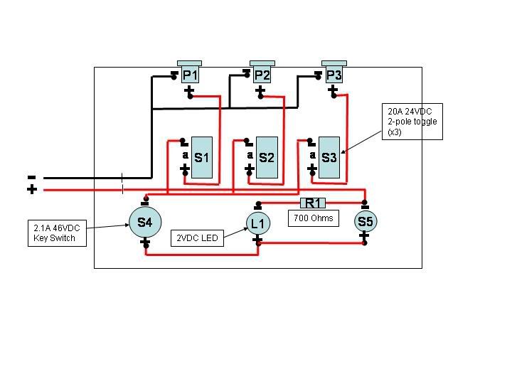
With the decision to build a MPR also came the need to buy or build a controller for composite motors/ignotors. After looking online for commercially available units and coming up short, I decided to build one to suit my needs. Who would have known I would find it on this forum! ;) Thanks to Michael (kiliman09) for his design. I decided to modify it a little, but the basic design was borrowed from here: https://www.rocketryforum.com/showthread.php?t=2129

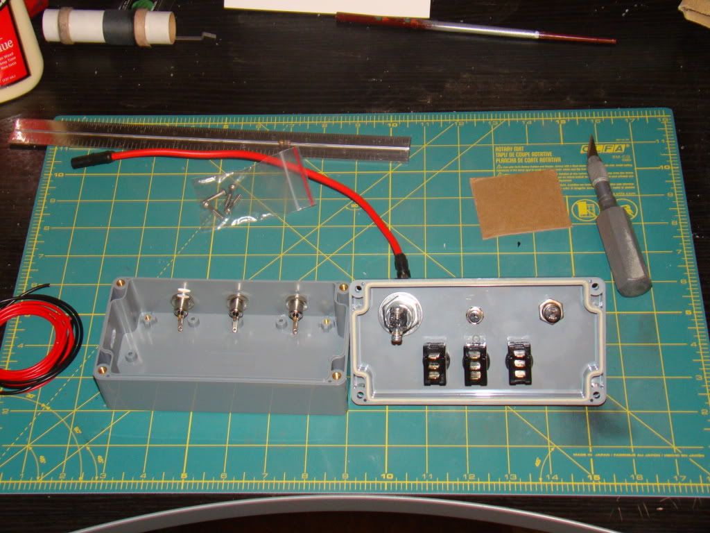
The box and basic component layout (inside)
DSC01268.jpg


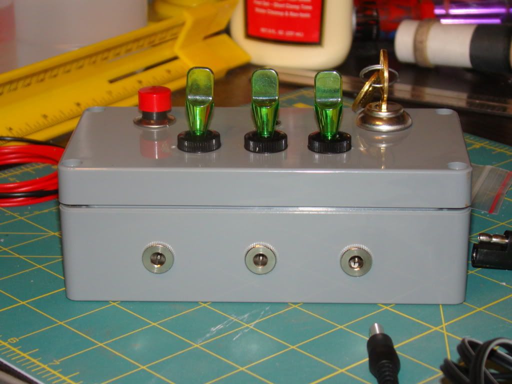
Outside showing the swiches and big red button
DSC01269.jpg


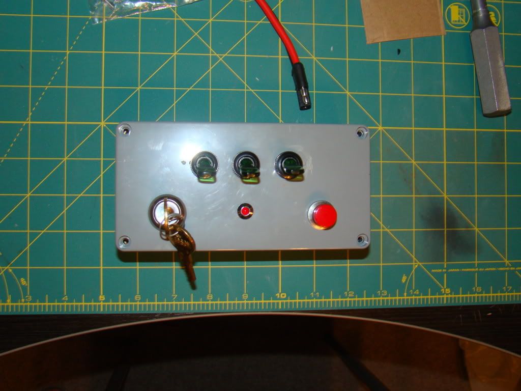
I wanted to streamline the apperance, so I substituted the pad terminals with easy plug-in recptacles, and lighted toggle switches because they're cool :cool:
DSC01271.jpg


External power is provided by a 2-pin insulated pigtail that will be cut in half and spliced into 30' of 12g Zip-wire with clips to a car battery, Odessey, or equivalalent on the other end
DSC01274.jpg


Each pad will be connected using a standard stereo connector spliced into 30' of 16g zip-wire to flat clips at the ignitors
DSC01275.jpg


I still have to wire it, so more pics later. Thanks for looking and any comments are appreciated!

Sean
 
What is the required amperage at 12v to ignite the ignitors? Does it differ between Copperheads, Q2, and FirstFire? What do most people use for E, F, and G motors?
 
If your launch controller is going to be used with Estes-type igniters, I think the rule of thumb is around two amps per igniter. (I could be wrong, I have slept since I remember reading about Estes igniters.)

I think most (all?) of the igniters for composite motors fire at much lower power levels. (Somebody who knows better want to chime in here?)

Also, you have to decide if you want one (or all ) launch position to be ready for a cluster launch, and again the driving design condition would be when using Estes-type igniters, and how big is the cluster. The choice is up to you.

You might want to wire one position for "heavy duty" use (clusters, Estes nichrome igniters, etc) and deliberately "de-rate" the other positions to slightly lower power levels for single composite motor (single igniter) designs. You might save a little money. OTOH, it would probably be nicer to go ahead and set up all launch stations for the heavier power loads, and make your system that much more flexible. That way, if your "Estes" station has a failure of some sort you can just shift to the next pad and keep on launching.
 
Thanks for the info. I read on another post that composite motor ignitors fire at ~5A, so I was building it to put at least 5A to each pad - probably closer to 20A. I plan to use Estes ignitors, Copperheads, Q2, and whatever else is out there with this controller. I also plan to launch singles, clusters (Estes or composite from a single pad), and have drag races with all three pads firing. In short, I want maximum flexibility.

It should be noted that I have virtually no experience with designing or building electrical components, so forgive my naivete. Aside from Heathkits I built in the '70s (complete with instructions), this is the first time I have tried to build anything like this. I appreciate any comments or suggestions.

Sean
 
Last edited:
Your system looks good but I would suggest you add a continuity light for each firing circuit. If any one circuit is not completed this system will show continuity from the others. Also you mention using low current ignitors, the current passed by a lamp will fire a Q2G2. If you use LED's they do not pass enough current to fire any ignitor. Ted
 
Your system looks good but I would suggest you add a continuity light for each firing circuit. If any one circuit is not completed this system will show continuity from the others. Also you mention using low current ignitors, the current passed by a lamp will fire a Q2G2. If you use LED's they do not pass enough current to fire any ignitor. Ted
Thanks for the input. The red LED has a 700 Ohm resistor installed upstream, and the LED is the system power-on indicator. Hopefully when the key is turned the light comes on and current flows through the closed toggles and the ignitors. Each of the three 20A 24V toggles is lit when switched on (closed) to indicate current through that circuit. The current to each toggle switch is inhibited at the red LED until it is shorted out by the launch button. I don't have good specs on my key switch, LED, or launch button, so I'm not sure if they can handle the full draw, and I don't know what that is. I'll be using a car battery, which can really pack a punch and I don't want to burn the thing up...
 
Ahhh so the toggle switches are the continuity indicators? Do they return to the no fire position when released? If yes, then you shouldn't have to worry about frying them. The rating given for them is likely for continuous use and the current will only flow through them when the are in all fire position. I use a 12V 80 amp battery with 10 ga. solid wire to an old Estes square box controller with 16 ga. wire to the tower and it works fine. Ted
 
Ahhh so the toggle switches are the continuity indicators? Do they return to the no fire position when released? If yes, then you shouldn't have to worry about frying them. The rating given for them is likely for continuous use and the current will only flow through them when the are in all fire position. I use a 12V 80 amp battery with 10 ga. solid wire to an old Estes square box controller with 16 ga. wire to the tower and it works fine. Ted
Yes, the swithces are continuity indicators to tell me which pads are armed. They don't automaticaly swith off when fired, although that would be a cool feature - maybe Controller v2 will have them if I can find them. Anyway, my thinking is that the arming switches won't have to handle the full current until the launch button is pressed, which should be no more than 3 sec (until the ignitor fires). While armed, they are flowing reduced current from the key switch, LED and resistor. So yes, the hope is that they will hold up. My key switch is rated at 2.1A 46VDC, and I don't know the spec on the launch button. I want to say that it was 5A 24VDC, but I threw out the package.

Here is a wiring diagram

controller.jpg


Where did you get the parts? Toggles, box, etc.
I got everything from a local electronics store. I just walked in with an idea and walked out with $100 worth of stuff, including 150' of wire. The staff was very helpful, but I'm not sure I communicated exactly how I wanted the controller to work. I should probably go back and make sure the parts I have will work now that I have a diagram.
 
Back
Top