2.63" (formerly 3" Mailing) Tube Printed Rocket

The Rocketry Forum

Help Support The Rocketry Forum:

This site may earn a commission from merchant affiliate links, including eBay, Amazon, and others.

thzero

Well-Known Member
TRF Supporter
Joined
Jun 4, 2018
Messages
1,287
Reaction score
924
Because I'm on a 3d printing kick decided to do something different, and just because. No performance, etc. goals. This is going to use a 3" mail tube with the nose cone, fins, etc. printed out of PETG and bolted together.

Capture of the three part nose cone, its simply too long for my printer and I like longer not stubby nose cones.

Capture1.PNG


Then the modular fin can. Fins are airfoil shaped; not sure if I will print them that way for the trial runs or not.

1611547743635.png

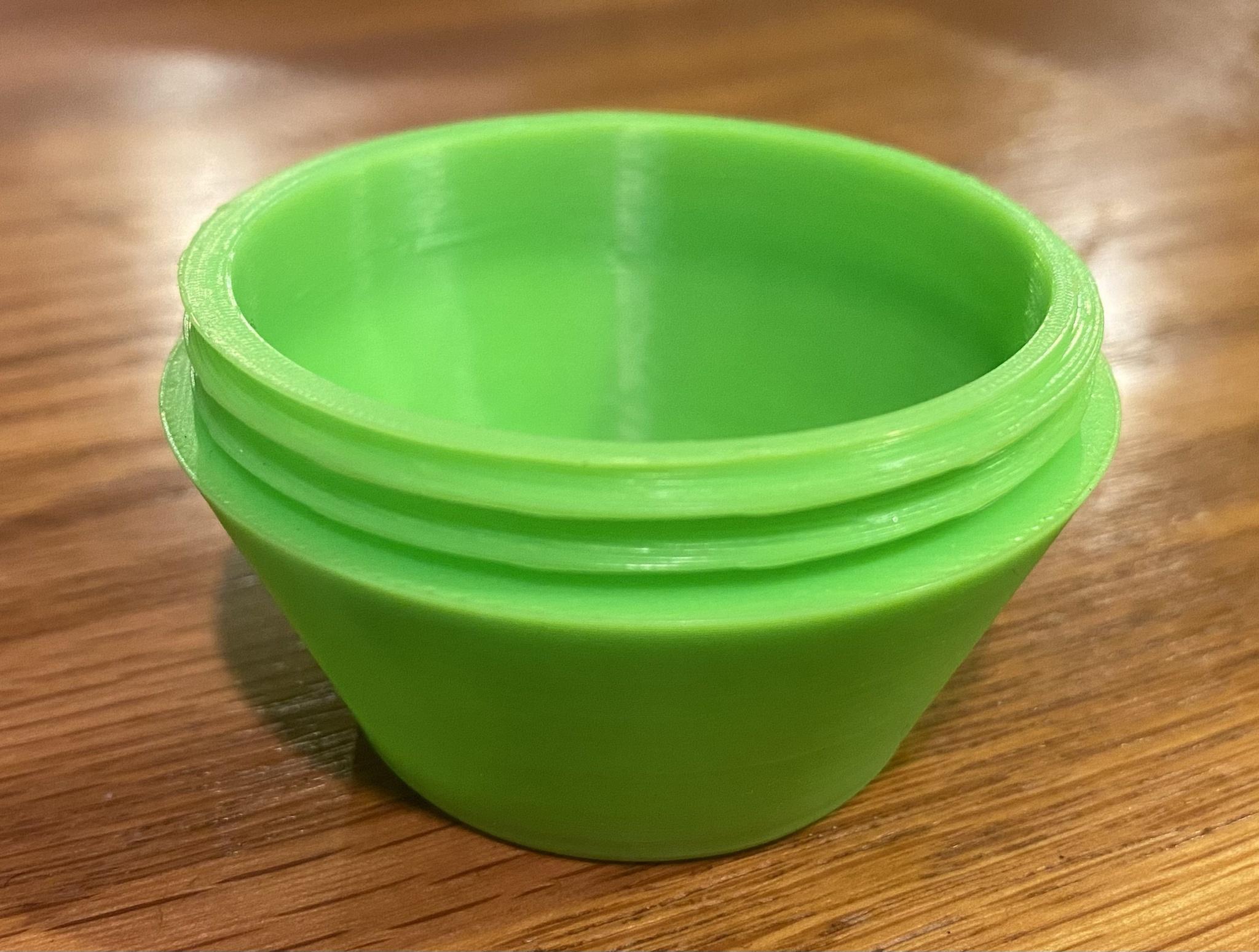
Fin can will take a standard 38mm LOC tube as a liner with an Aeropak retainer. Was going to print up a retainer, but my barely there CAD skills and threads are not working out too well.
 
Subbed.

I few a 3" mailing tube last year on an I140 if I recall properly. 3D printed nosecone and monolithic fincan/motor mount.

I've kicked around multiple different ways of doing the motor mount and fins as separate pieces and never got anything I really liked. Your design is better than anything I've come up with, hope it works out! 3D printing really opens up the door to using things like mailing tubes, using them easier than having to make your own nosecones with foam or whatever.

Here was my build: https://www.rocketryforum.com/threads/new-build-airmail.157906/

If you want a motor retainer, what I do is drill/tap holes in the bottom of the motor mount and then print a tailcone that has a pocket for the motor thrust ring to fit in. I've flown on up to a J450 with that design with zero issues to date...with how long the heat in on the plastic, it really doesn't do much to it. PLA, PLA Pro, Tough PLA, PETG...they've all worked.

Fincan/MMT (54mm in this case):
Fincan.PNG

Tailcone:
Tailcone 1.PNG
Tailcone 2.PNG
Tailcone Section.PNG
 
Very nice.

I had struggled with printing threads and then using removal extruding and then actually being able to print them where I can screw them together. Frustrating.

But I like the above approach too... easy enough to do with my minimal CAD skills.
 
Very nice.

I had struggled with printing threads and then using removal extruding and then actually being able to print them where I can screw them together. Frustrating.

But I like the above approach too... easy enough to do with my minimal CAD skills.

Same here. I'm entirely self taught on CAD, threads aren't something I can do...unless I'm tapping them with a physical tap, lol.
 
Tried the approach that Dustin showed above... might work out ok.

Capture.PNG


Capture.PNG

Either use PEM nuts, or a threaded inserts as the anchor points to screw the retainer too

And then the retainer

Capture.PNG

Capture1.PNG
 
Cool! I had an anchor point at the root of each fin, under the logic that there is more material there. Dunno that it's better or not, but that was the thinking at the time.
 
I was thinking of that too myself. Then I was thinking to use a PEM nut instead of inserts, and so this would work better. May change mind by time I end up printing.
 
Printed threads are really easy in Fusion 360 or Solidworks. You do have to compensate for some tolerance on dimensions due to it being extruded plastic rather than machined metal. It takes about 30 seconds to click a few times and generate these:

JWN3rTD.jpg
 
Fusion 360 for the win here too. I believe these are 2.25 x 11.5 threads. I had to use the loosest thread class, but these work without any post processing!

This is my Tube-Tastic that is also made of 3" shipping tubes. Nose cone, e-bay bulkheads, centering rings, and 1/4-turn e-bay retention, and rotation lock are all 3d printed. Really has been my testbed for rapid dual-deploy reflights and other abusive practices. Next few flights will involve warp 9 motors so things will be interrsting.
 

Attachments

  • 16117183083611571303977661333024.jpg
    16117183083611571303977661333024.jpg
    94.8 KB · Views: 33
  • 16117183877572746630846889983315.jpg
    16117183877572746630846889983315.jpg
    88.7 KB · Views: 33
I'm on Solidworks, still have one of their Home Use Licenses running. It's the only 3D modeling software I have any experience with, so that's what I use.

My fin cans are normally load bearing in 3D printed areas, not parts added onto a tube, which is why they tend to be pretty flat and bolt together instead of having printed threads.

Cool stuff!
 
Well, I have access to neither Fusion360 (omg, autodesk online everything is a confusing mess) nor Solidworks, so... thought they only had a HUL for like a year?
 
Last edited:
Locking ramps might be easier than threads. That's what I used on my Nike Apache here.

I tried to reduce the amount of features but still have the parts go together unambiguously and in alignment. Just a nice put together and then partial turn to lock.
 
Locking features require you to actually "design" something, whereas threads are simply a "click to insert thread" on the face of an object. It's ridiculously simple.
 
Well, I have access to neither Fusion360 (omg, autodesk online everything is a confusing mess) nor Solidworks, so... thought they only had a HUL for like a year?

They stopped approving HULs Oct 2019 I think. The way it is set up, you can't reinstall, you can't update, if your computer dies, you lose it...but as long as your computer stays as-is, you're OK to keep using. So...I'm running my computer with two SSDs in RAID 1 and I have a full image backup of it, lol. Planning on using SW2019 far into the future.
 
Locking features require you to actually "design" something, whereas threads are simply a "click to insert thread" on the face of an object. It's ridiculously simple.
I designed a locking feature 29mm motor retainer...yeah, it sucked, but I learned a ton about Solidworks and whatnot. It was more about the journey than the destination.
 
I installed Fusion in 2020, and their website says the one year home use license is renewable. I have not hit my one year yet, so I’ll see how it goes when that comes up.
 
Right now for test run - infill is 30%/cubic. wall count is 4. layer height is .14. If you have cura, here is the cura profile - so if there are suggestions, all ears.
 

Attachments

  • CCR6SE_Fin.zip
    237.8 KB · Views: 6
Only thing I'd suggest from what I see is a wider base to it so it has some stiffness. I usually run fincans at 50% infills, 4-5 solid layers, and .20 height, so not too far off. I'd be worried about flutter from what I can see of how it started to print though.
 
Yeah... it turned out smaller than I was predicting, so think I have some wiggle room. Having the printer makes tinkering with size, shape, etc. quite easy - previously I'd design something and then sent it out.
 
Another test print... came out ok. Probably could still be thicker, trailing edge of airflow is bit thin. Also worried about print layers being vertical across the surface. But at least the first test printer were I tried to get layers across the root of the fin didn't come out so nice and had to abort. Maybe it'll be ok by tossing on a layer of glass.

Image1.pngImage2.pngImage3.png
 
Looks good. How flexible is the fin? That's been a problem for me with printed fins (though I likely had some under extrusion problems.) And are there any tricks to generate the airfoil in CAD?
 
The print z axis direction concerns me...any "twist" or anything while under aero loading is going to basically try to shear the layers apart. That's one of the reasons I print mine vertically...hard to do when it's not part of the fincan though.

Only one way to see if it works, lol. :headspinning:
 
Back
Top