2.6" D-Region Tomahawk build

The Rocketry Forum

Help Support The Rocketry Forum:

This site may earn a commission from merchant affiliate links, including eBay, Amazon, and others.

jj94

Well-Known Member
Joined
Jan 17, 2009
Messages
4,023
Reaction score
0
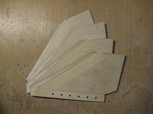
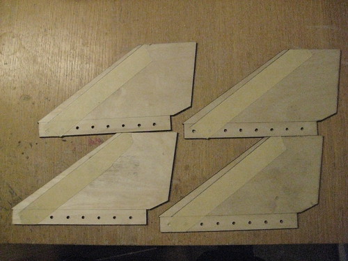
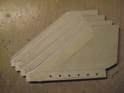
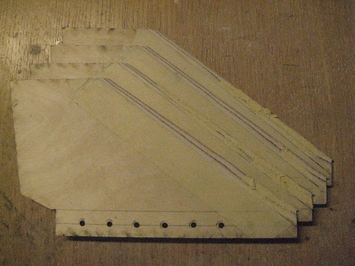
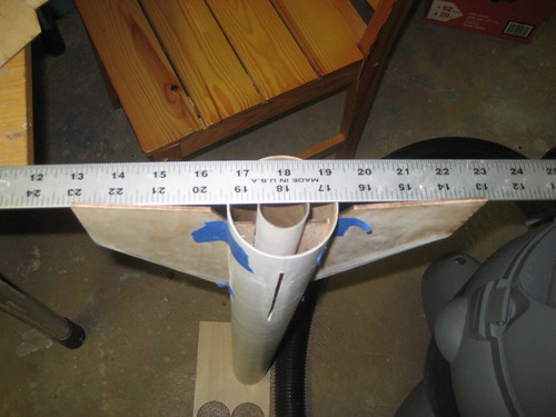
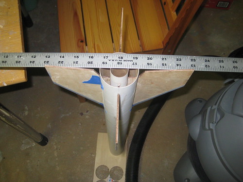
Well, this has been in the works for quite a while now. I started back in the summer of '08 and it has been fully built. I've just been too lazy to get some paint on it. I'm just now starting the build thread mainly because I forgot to make one sooner, and I thought some people might be interested. To start off, here is the Rocksim file.

View attachment D-Region Tomahawk.rkt
 
I didn't take too many pictures, as I was borrowing a camera. The camera I borrowed didn't produce very high quality pictures, so I'm sorry about that. I've since gotten a new camera, and I love it. But anyway, here are the pictures.

3432010946_c820069100.jpg

Here are the laser cut 1/8 ply fins on the table. I had them cut by Commonwealth, for $4 plus the costs of the wood. Masking tape was applied to the leading edges at a precise angle to aid with beveling. I used my Dremel with the paper sanding disks to complete the job.

3431196853_1dee872ec3.jpg

Here's another view of the fins laid out on the table. I drilled holes in the tabs for the foam to go through to get a better grip on the fins.

3431197181_f7bf937dfb.jpg

Here are the fins after beveling. I screwed up on the bevels near the top of the leading edge, but I took care of it with filler.

3431197601_7e24480c8a.jpg

As I said, I used filler to cover up the flaws in the bevels.

3431200735_46c8f00f69.jpg

A better view of the bevels. This is after I sanded down the filler.

3431199643_890b666649.jpg

On to the motor mount.
 
Last edited:
3431198633_f54d5f9b82.jpg

A close up of the forward centering ring. A hole was drilled through for an eye bolt.

3431201891_1f45547054.jpg

And here is the eye bolt in the centering ring. I epoxied it in with JB Weld, and also secured it down with a nut.

3431207901_b01f8b5317.jpg

Here's the motor mount with another centering ring installed. The top of the tabs from the through the wall fins will butt up against this centering ring for added strength and support.

3432017672_90fed19b51.jpg

Another close up of yet another eye bolt. This is the bulkhead that will connect the altimeter and payload bays to the shock cord. It's secured in the same fashion as the other eye bolt in the motor mount is.

3431204469_b761c06e0c.jpg

Here is the same bulkhead after it has been glued in and filleted into the coupler. Shown in the background is an extremely messy work table.

3431206773_610906c661.jpg

Some fin slots cut out.
 
Last edited:
3432023682_d969cd094b.jpg

My version of a cheap fin jig. While the wood glue is still wet, have the sides of opposite fins butt up against the side of a straight ruler to ensure good alignment.

3432024658_6043bf5fa7.jpg

Using the same method for the other two remaining fins.

3431210407_5e37aff55b.jpg

The fin can after internal fillets. I don't care for cleanliness inside the fin can. It's not like anyone will see the inside after the rocket is built. Oh, and the good alignment of the fins can also be pictured here.

3432026520_f846150019.jpg

Here is the fin can after being foamed. The foam has been cut down until the bottom of the fin tabs have been exposed so that another centering ring can be added to butt up against the tabs. Also a good example of the bad photo quality the camera was giving me, from what I mentioned earlier.

3432027730_3f8d7dfcf4.jpg

The second to last centering ring installed and filleted. The foam rose higher than expected so I had quite an amount of work to try to cleanly cut out the foam down to the fin tabs.

3432028456_358ecea99b.jpg

Here is some work on the altimeter bay. The altimeter will be mounted on a sled, and the sled with have two guides that will run down the length of these two screws. Nuts will be used to secure the sled.
 
Last edited:
3431213981_23974cf352.jpg

The completed altimeter bay.

Well, that's the end of the pictures for now. I took all of these back last year, the latest was in the beginning of fall. Tomorrow, I'm going to try and get some more pictures of the Tomahawk. Stay tuned.
 
Last edited:
I edited my posts and embedded the pictures using Flickr as the photohoster this time instead. The first time around was Picasa, and I guess it just wasn't working for me.
 
Is that the LOC messup D regions?

My dad has one. Its all the same accept his is DD and 54mm MD :p Built for a 30" long L motor

Ben
 
Nope. This is a scratch build. I built it using a lot of LOC parts though.
 
With holes in the fin tabs and foam in the can, those fins aren't going anywhere.
 
With holes in the fin tabs and foam in the can, those fins aren't going anywhere.

Yup. That's the main reason why I skimped on the external fillets, and partially on the internal ones. I only put the external fillets on to seal the body tube/fin joint and to make it smoother.
 
Back
Top