10" diameter JayHawk

The Rocketry Forum

Help Support The Rocketry Forum:

This site may earn a commission from merchant affiliate links, including eBay, Amazon, and others.
A piece of waxed paper was placed over this, and with a paint brush taped onto a three foot stick, smoothed into something that resembles a fillet.

I like this idea as a means to get compression and fill all along the fillet in a tight spot.
 
I like this idea as a means to get compression and fill all along the fillet in a tight spot.

Thanks. I would have liked it to be an option or even a forethought, but it was born of necessity. My hand fits into the space, so I believed I could reach in the whole way. Until the first time I tried, when I got stuck about halfway up my forearm. Hence the stick.

popeye.jpg
 
The interior fillets in the lower half of the body tube are now completed, so the aft ring gets put on permanently today. The aft ring is doubled, to provide a surface for mechanical fasteners if needed. There are two small holes in which screws attach the ring to the wing tang, two large holes for access to pour expanding foam into the tailcone, and two hardwood blocks for the rail buttons, one on each side. Beads of JB Weld are added to the inside of the body tube, and outside of the motor tube, at the position the ring will fit. These beads form into fillets as the ring is pressed into position. The body is then set vertical until the epoxy has set.

Centering Ring #1  (doubled).jpg
 
Last edited:
I am planning on flying two BoosterVision GearCam Digital Video Recorders on the Jayhawk forward body tube, one facing forward to watch the drogue and main recovery deployments, and the other facing aft to watch the ground (and wings). My friend and fellow WOOSH member Dennis B. built the very fine attachment bracket pictured and loaned it to me to clone. The GearCam, available here...

https://www.gearcam.com/gearcam/faq.htm

has a molded "C" channel, which fits into grooves cut into the bracket. The camera is then held against forward-aft movement by screws.

GearCam and bracket.jpg

GearCam on bracket.jpg
 
Last edited:
Thought I would post a few photos here to show that the Jayhawk design is ubiquitous. (I just learned what that word means, so now I use it everywhere.) These Jayhawks (and variants) should rightfully have been mentioned following post #49, the Jayhawk "family photo" of 26 Jun 2010.

(a) The first photo is Marty Vrstal's 4" JayHawk, featured on the cover of the September/October 2009 edition of "Sport Rocketry". Marty's excellent scale Jayhawk won the inaugural High Power Rocketry Upscale Competition at the NAR National Sport Launch in May 2009, by winning the popular vote (in the morning) AND having a perfect flight (in the afternoon), on a Cesaroni J285.

(b) In 1959, the US Navy and US Air Force issued a joint request for a new high-speed expendable target. Beechcraft won the competition, and the result was a small delta-winged drone with wingtip fins and a liquid-fuel rocket motor, now known as the "AQM-37". The production AQM-37A Jayhawk entered service with the US Navy in 1963. The AQM-37C is the current variant. (source - Greg Goebel / public domain)

(c) The third photo is an Air Force AQM-81A Firebolt, The Firebolt was based on the AQM-37, but used a throttleable hybrid rocket motor. The AQM-81 test program was completed in 1984. No follow-on contract for Firebolt production was awarded, presumably because it was significantly more expensive than the simpler expendable AQM-37. (source - Andreas Parsch). (I personally like their recovery system, a big net.)

(d) The XB-70 Valkyrie was a prototype bomber for the USAF. Designed in the late 1950s, it was a large six-engined aircraft able to fly Mach 3+ at an altitude of 70,000 ft (21,000 m), which would have allowed it to avoid interceptors, the only effective anti-bomber weapon at the time. Two XB-70 prototypes were built. The introduction of effective high-altitude surface-to-air missiles led to the cancellation of the B-70 program in 1961. The XB-70A aircraft were used in supersonic test flights from 1964 to 1969, performing research for the design of large supersonic aircraft. One prototype crashed following a midair collision in 1966; the other is on display at the National Museum of the United States Air Force in Ohio. (source - Wikipedia)

(e) Fireball XL5 was a science fiction-themed television show following the missions of spaceship Fireball XL5, commanded by Colonel Steve Zodiac of the World Space Patrol. The show aired on NBC from 1963 through September 1965, and featured Gerry Anderson's Supermarionation. Thirty-nine black and white half-hour episodes were made on 35mm film: all future Anderson series would be produced in color. (source - Wikipedia)

(f) Not pictured here due to the 5 picture limit of the forum, is the full-size Jayhawk, built and flown by Dirk and Erik Gates of Gates Brothers Rocketry. (It is pictured in post #31, 15 April 2010.) The brothers and their rocket are the inspiration for this project. You are missed, Erik.

Marty Vrstal's 4%22 JayHawk.jpg

Beech AQM-37C Jayhawk.jpg

AQM-81A Firebolt.jpg

USAF XB-70.jpg

Fireball XL-5.jpg
 
Last edited:
This week we continued working on the interior fillets of the motor section body tube. With centering ring #1 now permanently in place, I removed ring #3 to expose the inside of the body tube forward of ring #2. (They are numbered from the aft end forward.) The first and second photos are looking down into the opening, before and after removing the forward ring. While not visible in the photo, I was able to peer with a flashlight into the "foam access" holes in ring #2 to verify the quality and completeness of fillets formed on the forward side of ring #1 when it was pressed into position last week. The third photo shows the fiberglass tape reinforced fillets added to the forward side of centering ring #2. This is in pretty tight quarters, so the work was once again done with a paint brush taped to a 24" stick. Painter's tape was added to the all-threads to protect them from inadvertent epoxy application during this process. The threads need to be protected for the later and permanent re-installation of ring #3.

added note...

The multiple plies of the Baltic Birch plywood wings are evident on the wing tang. The fourth and fifth attached photos compare "Baltic Birch" plywood to "just-plain Birch" plywood. Baltic Birch plywood has a higher ply count, all the plies are birch, and it is virtually free of voids. This gives Baltic Birch tremendous strength compared to other types of plywood. With the second plywood, I'm not entirely sure that any ply other than the face veneer is even birch. Lower ply count gives it less strength and makes it less resistant to expansion or warping. Baltic birch is more difficult to find. In Rockford, Lowes and Home Depot only carry regular birch plywood. I was able to get a few 48" x 96" sheets of Baltic Birch plywood at Menards.

inside of joint coupler.jpg

inside body tube, top of ring #2.jpg

glass and fillets on top of ring #2.jpg

Baltic Birch plywood.jpg

Birch plywood.jpg
 
Last edited:
Hey Sather, Thanks for adding a pic and write up of my Jayhawk...that was a cool surprise while catching up on your thread.
 
Hey Sather, Thanks for adding a pic and write up of my Jayhawk...that was a cool surprise while catching up on your thread.

That is one beautiful, museum-quality rocket, even more so since you fly it.

it isnt finished.jpg
 
My goal this week is to get the tailcone on. All the interior fillets are now complete, and the aft centering (#1) is in it's permanent position, with fillets fore and aft. The top centering ring (#3) is ready to be put in, but I need the tailcone installed first, as I have access holes in rings #1 and #2 to pour 2-part expanding foam into the tailcone.

In the first photo, the tailcone ring (#0) has been carefully measured and tacked into position with CA. The doubler is temporarily taped above this until the CA sets. In the second photo, the doubler has been lowered and is being glued to the tailcone ring. When this is done, I will install ribs along the aft section of motor tube, between the aft centering ring (#1) and the tailcone ring (#0). These ribs brace the tailcone ring against the aft centering ring, relieving the tailcone ring-to-motor tube joint, and the relatively fragile tailcone itself, of compression loads during boost. The goal is to transfer a majority of the force of thrust (at the baseplate of the Aero Pack motor retention body) to the wing and body tubes (where all the weight is) via the ring #1-to-wing tang joint (pushing), with a minority carried by the motor tube-to-wing tang joint (pulling).

Note that the outside edge of the tailcone ring is beveled to fit flush inside the tailcone proper. There is also a notch formed just above this edge, since the outside diameter of the doubler ring is slightly smaller than the tailcone ring itself. This was done to allow an epoxy pour to "flow" around the base of the ribs and fill in a fillet at the perimeter of the tailcone ring, where it meets the tailcone.

tailcone ring #0 tacked in place.jpg

tailcone ring #0 doubled.jpg
 
Last edited:
This morning I cut the 6 thrust ribs (pictured). I originally cut a few each in 1/4" and 1/2" baltic birch to compare them. The 1/2" added only 0.8 ounces per rib, so I decided to make all six 1/2" thick. Two line up directly under the wing tang, the remainder are spaced out at 60° angles. They are temporarily placed in position in photo 3. (I like the look of this, sort of a Mars Snooper effect. Kind of a shame to cover up with the tailcone. May use this un-shrouded on a future project.) Should have them all epoxied in place this afternoon.

thrust rib template.jpeg

thrust ribs cut x 6.jpeg

thrust rings (Mars Snooper).jpeg
 
Last edited:
Yesterday I finished epoxying the ribs in position. This was done with the rocket oriented tail-end up. JB Weld was used for everything that touches the motor tube (heat source). Photo #1 shows this last night after the epoxy had set up and the rocket returned to upright. The next steps weren't photographed due to the amount of epoxy on my hands during the process. I added a significant fillet of epoxy to the top side of the tailcone ring-to-motor tube joint, as well as beads of epoxy to the INSIDE of the aft ends of both the body tube and the tailcone, and also to the OUTSIDE of the tailcone ring and tailcone shoulder. (Popsicle sticks are GREAT!) Then, while doing my best to keep all this epoxy from sagging or dripping, I fit the tailcone in position, pressing it up inside the body tube and against the tailcone ring to form fillets from the epoxy beads. Photo #2 is this morning, after everything has cured.

thrust ribs epoxied.jpeg

tailcone epoxied.jpeg
 
Last edited:
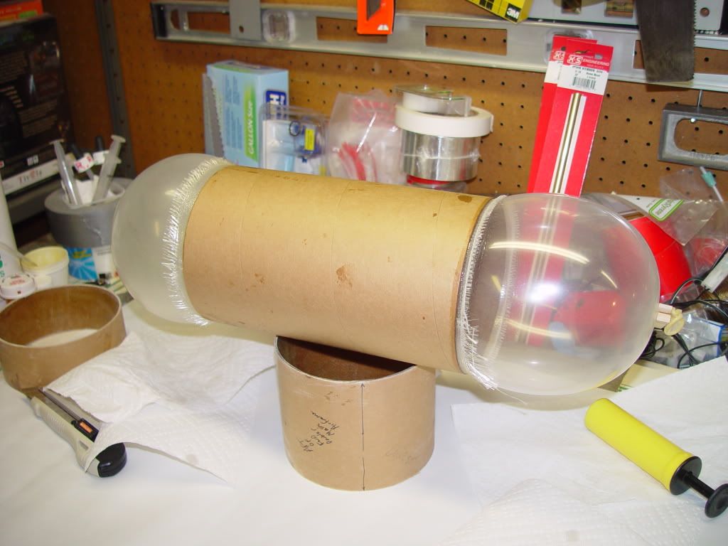
The avionics bay sits within the lower half of the rocket, with the upper body tube removable for transport. The avionics bay therefore doubles as a joint to attach the upper tube. While the upper tube is non load bearing during recovery, it does carry a good deal of weight during boost. (The nose cone carries ballast for stability.) Therefore, I am planning to glass and CF the INSIDE of the coupler for rigidity. I have seen this done a few times following various builds on the forum, but I have never attempted it before, so I am wide open to suggestions here. None my techniques for glassing the OUTSIDE of tubes transfer to this. (Can't use a rotisserie, etc...) How do you keep the cloth from collapsing from it's own weight during wetting. I assume wax paper and a big balloon during cure. The tube is 19" long and 10" inside diameter. I have been putting this off, but my 36" balloons came today, so I have no more excuses.

avionics bay : coupler w: balloon.jpeg
 
Inside FG is very easy for a tube this size, it's the smaller tubes that are tough (where you have to use dowels and such).

Just apply epoxy to the inside of the tube with a brush. Be generous, an extra 1/4 oz. isn't going to hurt you and will make things easier. Put on protective gloves. Pick up your pre-cut FG cloth and fold in the ends with both hands at one time. Lay in the middle semi-aligned and unroll and press with your hands. The extra epoxy applied should allow you to push/shift the piece to get it just right. It has enough tack to stick to the walls and will not sag.

The only real challenge is the length @ 19" so if I were you, I'd do two pieces, one from each end and have them overlap a bit in the middle of the tube.
 
Last edited:
Inside FG is very easy for a tube this size, it's the smaller tubes that are tough (where you have to use dowels and such).

Just apply epoxy to the inside of the tube with a brush. Be generous, an extra 1/4 oz. isn't going to hurt you and will make things easier. Put on protective gloves. Pick up your pre-cut FG cloth and fold in the ends with both hands at one time. Lay in the middle semi-aligned and unroll and press with your hands. The extra epoxy applied should allow you to push/shift the piece to get it just right. It has enough tack to stick to the walls and will not sag.

The only real challenge is the length @ 19" so if I were you, I'd do two pieces, one from each end and have them overlap a bit in the middle of the tube.

For better results, get an extra large rubber balloon and blow it up inside the coupler after adding the glass. It will compress the glass against the coupler, and give you a nice smooth finish. Finding a large enough balloon for this size of coupler might be a challenge though.
 
For better results, get an extra large rubber balloon and blow it up inside the coupler after adding the glass. It will compress the glass against the coupler, and give you a nice smooth finish. Finding a large enough balloon for this size of coupler might be a challenge though.

I had anticipated that, from having seen a few done that way on TRF builds (thanks). I ended up with a ten-pack of 36" balloons from the Balloon Place... https://www.balloonplace.com/catalog/Qualatex_latex.html They came today, and I trial inflated one inside the coupler to check the fit. (With an air compressor, or I'd still be there puffing!) Interestingly enough, the 3' balloons are only $2.89 each, while 4' ones are $20.95 each!

I'm now shopping around for some really wide wax paper. I had fiberglassed the exterior of two different exercise balls on my upscale Death Star project. On the first, the rubber ball fell cleanly away from the glass when deflated, but the second ball remains permanently affixed to the inside surface of the fiberglass. On this avionics bay coupler, I plan on using wax paper between the glass and the balloon to avoid that problem. It worked great when glassing and clamping the wing exterior surfaces. Nothing sticks to it.

Screen shot 2010-07-26 at 2.29.23 PM.png
 
Last edited:
As we get closer to completion and launch day, I have also been planning the recovery setup. I plan on sleeving the entire forward body tube. I have to add weight up front anyway, might as well make it useful. Then the inside diameter of the payload bay is 9.5". Of the 46" total length, 8.5" is used over the avionics coupler, and the nose cone shoulder is 7.5". This leaves me 26" for main recovery gear and 4" for the plug. (The plug is basically a piston that sits on the shoulder of the cargo bay sleeve. It reduces the total volume (and BP required) to eject the nose cone.) The drogue parachute and shock cords fit inside the nose cone, forward of the plug.

In the main payload bay, three loaded Giant Leap TAC-3C kevlar deployment bags fit side by side, which they need to for a clean deployment, without getting stuck while being pulled out by the drogue after release of the tether. I am checking into getting them stitched together as in the attached rough sketch. (This is an idea I blatantly stole from the Gates Brothers, who had stitched together two bags for the twin mains of their full-size Jayhawk. Thanks!) They need six seams (2 lines of stitching between each bag) to be stitched together along the backside, at 2" intervals, to leave a small tunnel up the middle for a short strap, from the Defy Gravity Tether to a quicklink joining the three straps at the top of the bags. This quicklink also captures the drogue shock cord, and holds that and the 3 bags until main deployment altitude. The tether then releases the short strap, allowing the drogue to pull out the main bags together, and then pull them off of the three main chutes simultaneously. In theory.

Screen shot 2010-07-26 at 4.28.08 PM.png
 
Last edited:
For better results, get an extra large rubber balloon and blow it up inside the coupler after adding the glass. It will compress the glass against the coupler, and give you a nice smooth finish. Finding a large enough balloon for this size of coupler might be a challenge though.

I did about six couplers for may level 3 and got it by the last few. Wax paper was a bad idea, the epoxy was able to penetrate over the 3 hour or so cure, and was hard to get off, and also caused wrinkles. I found the using the balloon alone worked great, once the epoxy (West) was fully cured, when the air was let out, the balloon slowly returned to its original size and released on its own. I found that the glass trimmed so it went past the end of the couple as little as possible worked best. Edit-added pics.

DSC00576.jpg

DSC00581.jpg
 
Last edited:
Thanks. Those are some great techniques and nice looking glass work. Got me motivated to finally get around to doing my third tube. This one will be at the top of the stack, and although I would prefer an invisible seam at the nose cone, practicality dictates otherwise. One of my early tether flights suffered a 6" zipper at apogee, in a stock 5.5" LOC cardboard tube. Even though the two MAWD's and the Tether all operated perfectly, the zipper "captured" the drogue shock cord and kept it from pulling out the main deployment bag. That is one of the limiting factors in this type of deployment... no redundancy. You lose the drogue in a conventional dual deployment, you get another shot at a parachute with the main event. You lose the drogue in a tethered deployment, you're pretty much done. Sort of like comparing parallel and series circuits. One is independent, the other sequential.

I am constantly running failure mode analyses in my head, often at the expense of other, higher priority tasks (chores, honey do lists, etc.), and protecting the drogue and her shock cord is a recurring theme. Friend and fellow WOOSH member Dave F. had suggested the idea of zipper-proofing the body tube by banding it. I considered a long radiator hose clamp, but ruled that out as the relatively sharp edge could cut through the drogue shock cord while stopping a zipper - the cure being worse than the disease. I settled on a thin nylon strap cut from flexible handcuffs. This is very thin (<1/8") and very strong (necessarily), with rounded edges (to not cut your wrists). It is superglued near the front edge of the body tube, to be in position when the fiberglass cloth is added later.

nylon flex cuff added.jpeg
 
Last edited:
It occurred to me in hindsight (as usual), that the very slight rise over the edge of the nylon band might cause an air pocket in the subsequent glass layer, so I added a quick fillet of 30 minute epoxy and micro balloon filler. Here the first edge is being done.

Jayhawk band fillet.jpg
 
Last edited:
Continuing progress on the aft end of the rocket. The motor tube and tailcone extended about 1/4" past the tailcone ring. (As planned... better to err a little too long than to be a little too short.) I had trimmed the excess fiberglass near to flush with the wood, by hand with a Dremel tool and high speed cutting wheel. Very happy to find no voids in the internal epoxy (JB Weld) fillets between components, so I can set her upright and pour in the expanding foam without it leaking all over the place.

trimming tailcone.jpg
 
Last edited:
It started off a nice day today, so I hauled the Jayhawk motor section (now 50 pounds) outside to do a little sanding. After cleaning off the dust and getting her back inside before it started raining, I trial fit the Aero Pack retainer body, pictured here with a Rouse Tech 98mm motor case and the Cesaroni N3180 nozzle and unique aft closure. Still on timeline for Midwest Power, which now has a published date of 29-31 October 2010.

Aero Pack trial fit.jpg

Screen shot 2010-08-02 at 4.29.10 PM.png
 
Last edited:
Thanks, guys. Marty... It will be great to see you again. Are you bringing a Jayhawk to fly? Tim... I look forward to meeting you in person and seeing your "Hope-N-Pray" fly. I got a lot of good tips from watching her build thread. Cheers! :cheers:
 
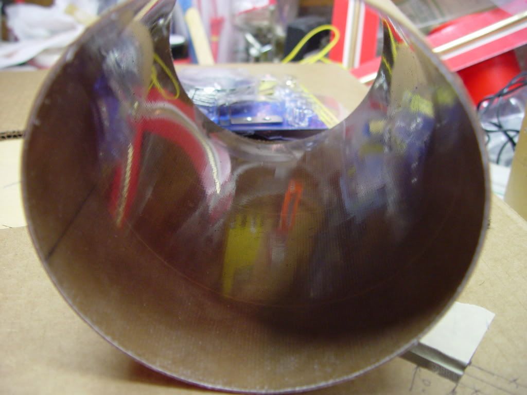
I took the plunge and wrapped the inside of the avioncs bay / body joint coupler with 2 layers of 5.7 ounce, plain weave carbon fiber. (Thanks to those who provided pointers for this procedure.) The first photo shows the CF being cut to fit. I rolled this up, marked a straight line longitudinally inside the coupler, wet the inside of the coupler with West Systems epoxy, and lined up one edge of the carbon fiber roll with the line. I then unrolled the CF about 8" at a time, while continuing to apply epoxy to the cloth and pressing it in place. The second photo shows a heavy latex ballon inflated inside the coupler to hold the CF tightly against the coupler during epoxy cure. A few things I learned here...

(a) 2 layers in one session was a bit ambitious. I was lucky there were no complications, as the ability to correct alignment issues was pretty much gone about halfway through it.

(b) I had used 3M Super 77 spray adhesive on the cut edges of the carbon fiber cloth to minimize fraying. This, of course, all stuck together when rolled up, which made unrolling it inside a 19" long epoxy soaked tube a bit of a challenge. Fortunately, the stuck edges were all exterior to the tube, and I had left my scissors within arms reach, so I was able to avoid becoming Br'er Rabbit. Barely.

(c) Carbon fiber is conductive and therefore electrically shields the avionics bay. It doesn't affect my planned use of PerfectFlite MAWD altimeters, but does restrict my placement of the tracking beacon and/or GPS transmitter from the av bay. The good news is the rocket will only go to about 7,500 feet and stay in sight. As long as the main doesn't come at apogee.

cutting CF to fit.jpg

balloon during cure.jpg
 
Last edited:
Sather...Yes, that's the plan. My wife has to work that weekend, I may come down solo...who knows? I am looking forward to ECOF at the end of August. Will your Jayhawk be making any shakedown flights there?
 
I am looking forward to ECOF at the end of August. Will your Jayhawk be making any shakedown flights there?

I have two other projects approaching completion for ECOF, but the Jayhawk won't be ready by then. Dan K. and I will be flying our twin 5.5" upscale Death Stars (https://www.rocketryforum.com/showthread.php?t=11861) in the Star Wars theme launch, and I have a separate parallel-stage (6 strap-on boosters) entry in the Booster Challenge. I consider MWP the shakedown opportunity for the Jayhawk. If she flies well there, a road trip to Argonia KS for LDRS in 2011 is in the offing.
 
Last edited:
I did about six couplers for may level 3 and got it by the last few. Wax paper was a bad idea, the epoxy was able to penetrate over the 3 hour or so cure, and was hard to get off, and also caused wrinkles. I found the using the balloon alone worked great, once the epoxy (West) was fully cured, when the air was let out, the balloon slowly returned to its original size and released on its own. I found that the glass trimmed so it went past the end of the couple as little as possible worked best.

Wax paper is really bad for use with epoxy. It's will allow the epoxy to penetrate it, as you found out the hard way. Try parchment paper next time. It is impregnated with silicone and really works.

It's really good for baking cookies as well! :D Imagine that, using "rocket stuff" in the kitchen!:y:
 
Wax paper will allow the epoxy to penetrate it, as you found out the hard way. Try parchment paper next time.

Actually, I was lucky. I didn't have any problems with the wax paper that I used. And I used lots of it, both in foaming the wing cavities and laminating the CF and glass cloth to the wing surfaces. Maybe it is brand specific, or related to epoxy cure time / temperature, (I use slow hardener). I used Reynolds brand "CUT-RITE" wax paper, which I purchased more for cheap price than brand name, 'cause I literally used over four hundred square feet of it. I let it sit overnight most of the time, and it peeled off easily in the morning. The only after-effect I noticed was, since I overlapped the foot wide paper when working with larger areas, you can see the overlap edge. This should sand smooth easily with the primer paint prep.

I did notice, though, that the wax paper was penetrated by the epoxy. I assumed at the time it was out-gassing. I used wax paper in my presses when laminating the wings, to protect the press table surfaces and NOT epoxy them to the wings. The wing lamination press used extra (abandoned) wings, and the winglet press used squares cut from a ping pong table. All of these had "ghosts" of the epoxied pieces on them after removal, kind of a "shroud of Turin" effect. This didn't really bother me, as all of these boards were expendable. I was just happy that they came off when unclamped. Would definitely NOT want to assume wax paper is impenetrable or able to protect anything important. Parchment paper sounds better for that. I'll have to get some. Thanks.
 
Last edited:
Back
Top