1/8" or 1/4" plywood? Is there a rule of thumb for fins and MMT rings?

The Rocketry Forum

Help Support The Rocketry Forum:

This site may earn a commission from merchant affiliate links, including eBay, Amazon, and others.

Jimmy D. Jones

Active Member
Joined
Jan 22, 2022
Messages
39
Reaction score
5
I was wondering about the selection of either 1/8" or 1/4" plywood fins and MMT rings?

Does the choice depend on the motor size (G, H, J?) or acceleration expected from a sim?

Is there a rule of thumb on this for fins and MMT rings as to when you bump it up from 1/8" to 1/4" plywood?
 
Experience..... In most cases my CR's are 1/4", but the fins can be 1/8 or 1/4, with or without Fiberglass lamination. I watched a prototype split fin rocket turn to confetti on a K550 it had 1/8" birch ply fins, yet I have a similar rocket with same thickness and similar profile fins with two layers of FG, that loves K motors. Experience, its part of the reason we ask people to spend time flying at each cert level before moving to the next.
 
Last edited:
I like 1/4" for centering rings as it gives me a place to anchor for my rail buttons. Fin thickness depends on the design of the fin.
 
I like to build a fin can with the entire fin root extended to the motor tube. This makes the centering rings less important as structural members and I think it makes the fins stronger as well.

The biggest thing I've built was a 4" diameter rocket sized for level 1 H and I motors. I used ply, I think 1/8". Basically I was following what was used in similar LOC kits. So since this thread is asking about rules of thumb, I would suggest starting with similar dimensions to what are used in similar size kits by LOC and other manufacturers. If you get to a big enough rocket to consider 1/4" ply for fins, I wonder if you should be using G10 instead.
 
I have a lot of rockets. I fly L1. Almost all the fins are 1/4" ply. There are a few with 1/8" fins. Those were usually light or the fins were bigger that a normal size. Almost all the CR's and bulkheads are 1'/4". Nothing I have has any FG or CF on it. I have a couple of MD rockets with what started out as 1'4" ply fins. Sanded them a lot. Two of the rockets are capable of supersonic flight. If they shred I'll try again. I/8" ply breaks easily on a dry lake bed. My rockets average 3 to 6 lbs.
 
There's no reason for thin fins on a low and slow 4" rocket. I've got one with 1/8'' fins, and it's a bit silly. Go fiberglass, if you need thin fins.

1/4" ply all the way around.
 
I use 1/8th as centering rings in low power, and basswood 3/32 for fins. Mid power is all 1/4 ply on cr and 1/8 ply or basswood on the fins, or thicker ply for bigger fins. High power could be 1/8th basswood fins, all the way up to 1/4 G10 Fiberglass or other composite layup. But the real defining characteristic you need is Strength. Use wood or glass that is strong enough for the task at hand.
 
Kind of like asking "what is the right size car?" You want the materials to be as lightweight as possible while still providing the structural support necessary. You didn't mention what your tube material is. Cardboard? Phenolic? Some sort of composite? Nor did you mention what size of tube. 1/8" in a one-inch tube is way different than 1/8" in an 8" tube.
 
This EZI-65 is set up with a 54mm motor tube and 1/4" plywood for the fins and centering rings. I regularly use AeroTech I, J and K motors in it. I have not flown it yet on a large K, like a K805 or K1050, but hopefully soon.

TMO_12-08-2018_Launch.jpg
 
It depends on the design - what the max G's the rocket is going to pull, max velocity it is going to reach (especially if it is transonic). My general rule of thumb is to use 1/8" fins and CR's on 2.2" airframes and lower, 3/16" on 2.6" - 3" airframes and 1/4" on 4" airframes, as a starting point. Once the fins are designed I run the fins through FinSim and the Finflutter spreadsheet to see if they'll survive the G's and speeds. If not, I go up a size. If they easily survive, I will go down a size to save weight. If I am using a U-bolt or eyebolt on the top CR, I might go extra thick on that one. If I am epoxying a kevlar leader to the MMT, I'll keep the top CR the same as the others. I use quality epoxy on these structural components (Aeropoxy, West Systems or Rocketpoxy).

I'm going to all basswood for LPR scratch build fins - you can easily go down one size thickness from balsa with better strength and minimal weight penalty. It's a lot easier to work with, more consistent in weight and strength and easier to finish. If I don't have the right size fiber or cardstock CR's handy for an LPR build, I'll cut them out of Basswood.

When you use the FinSim program and spreadsheet - are you using the material properties listed in them?
 
I found the materials sheets a little short when it came to plywood data, so I hunted down some additional tables and added them to a tab in the spreadsheet. I manually use different values in both Finsim and Finflutter if I am not using 3 ply 1/4" plywood (I often use 3/16" and 1/8" for fins and usually use 5 ply birch). The tables are a bit challenging to interpret (the table provides sheer modulus by 15-degree angles), so I take the lowest value for the plywood I'm using. I figure that provides an additional margin of safety. Finflutter provides a more conservative value than Finsim, so I generally use that as my design value - more margin of safety.

It's actually pretty amazing - 1/4" 5 ply birch can handle close to Mach 2 without tip-to-tip enhancements. You really don't need fiberglass or CF until you start exceeding Mach 2.

I've attached a spreadsheet with a copy of my sheer modulus tab.
 

Attachments

  • Sheer Modulus Tables.xlsx
    1.2 MB · Views: 16
I found the materials sheets a little short when it came to plywood data, so I hunted down some additional tables and added them to a tab in the spreadsheet. I manually use different values in both Finsim and Finflutter if I am not using 3 ply 1/4" plywood (I often use 3/16" and 1/8" for fins and usually use 5 ply birch). The tables are a bit challenging to interpret (the table provides sheer modulus by 15-degree angles), so I take the lowest value for the plywood I'm using. I figure that provides an additional margin of safety. Finflutter provides a more conservative value than Finsim, so I generally use that as my design value - more margin of safety.

It's actually pretty amazing - 1/4" 5 ply birch can handle close to Mach 2 without tip-to-tip enhancements. You really don't need fiberglass or CF until you start exceeding Mach 2.

I've attached a spreadsheet with a copy of my sheer modulus tab.

Thanks for the spreadsheet. I use the FinSim program and the spreadsheet too.

Is the "left" table, with the 15-degree values, for the birch? Where did you find that?

What are your fin profiles that allow you to get near Mach 2? The flutter velocity is dependent on root chord, tip chord and span. And of course the Shear Modulus for the plywood.
 
I can't tell you where I got the table, I found it on the internet and copied it into the spreadsheet. I have way too many saved URL's as it is to save all of them. If you search for plywood sheer modulus you'll find a lot of entries, many being technical papers. I did not do an exhaustive search, I found this table and it had 5 ply numbers (which is what I use), so I went with it.

I believe the table is for birch plywood although the table doesn't state that. I would not expect the values to be this high if it was just standard, Home Depot cheapo plywood.

I have found in running sims that the best shape has a tip cord of length zero. It makes sense to me because if the tip cord is greater than zero, then you have a flat surface of some length from tip to root that the air pressure can work on, and which would augment oscillation (flutter). With a tip cord of zero length, the amount of pressure from root to tip is going to vary in proportion to the surface area, with more at the base and none at the tip. It makes sense to me that that would make fin flutter less likely than, say, a fin that has a square profile (root cord and tip cords equal).

I have not done sims with varying the sweep length, but my gut tells me the sweep length should shorter (2/3 ?) of the root cord, with the root cord being a fair amount longer than the semi span so that the fin has a low profile from root to tip. The longer root cord provides the fin area needed for stability while minimizing the semi span reduces the stress (higher torque) on the ply layers if the fin is approaching Max Q. TTW fins would add additional strength due to the rigidity provided by the fin can and attachment to the MMT. If I had unlimited time, I would love to build a fleet to test these theories to destruction, but that ain't gonna happen...

I thought the same thing about the tip chord length; increase and the torsion increases, decrease and the torsion decreases. Then I had it pointed out to me that I had not selected the correct analysis in FinSim. The program was opening in the "Classical 2D Lift Slope" analysis and not in the "NACA 4197" analysis. Once I corrected for the analysis the velocity went the other way; increase the tip chord and velocity increased, decrease the tip chord and velocity decreased. The sweep angle showed little to no effect. This is if you hold the root chord and fin span constant.
 
It depends.
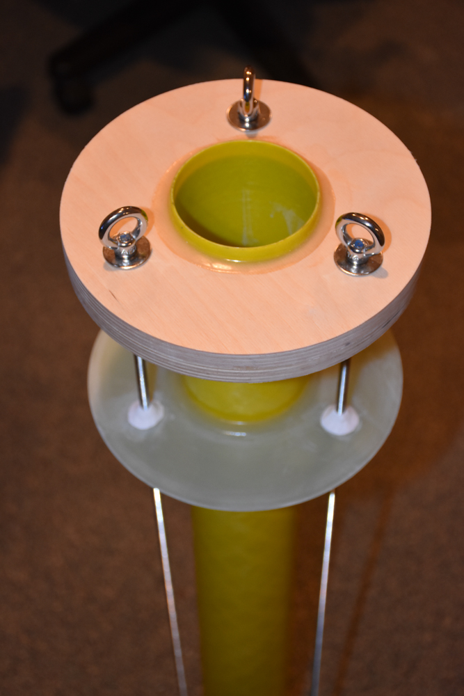
This motor mount for my scratch built 8" diameter upscale Frenzy has three centering rings. The aft two rings are 3/16" fiberglass and the forward ring is 1" plywood. The big 1" thick ring allows the motor mount to be attached to the airframe tube using both screws and epoxy. It also provides very secure attachment points for the recovery harness.

33653724951_2a274b5a15_o.jpg
 
I thought the same thing about the tip chord length; increase and the torsion increases, decrease and the torsion decreases. Then I had it pointed out to me that I had not selected the correct analysis in FinSim. The program was opening in the "Classical 2D Lift Slope" analysis and not in the "NACA 4197" analysis. Once I corrected for the analysis the velocity went the other way; increase the tip chord and velocity increased, decrease the tip chord and velocity decreased. The sweep angle showed little to no effect. This is if you hold the root chord and fin span constant.
Hmmm. Classical 2D Lift Slope does nothing in Finsim for me. NACA 4197 is the only option that works.
 
Hmmm. Classical 2D Lift Slope does nothing in Finsim for me. NACA 4197 is the only option that works.

Are you running John's new FinSim Lite version? I installed it the other week. But it wrote overtop my old FinSim version, so I can't backcheck it. But the spreadsheet still works fine. You can choose Classical 2D, Barrowman 3D and NACA in the Lite version.
 
I have the old version. I didn't know he had an updated version. He was not selling it to people based on their political persuasion at one point.
 
I have the old version. I didn't know he had an updated version. He was not selling it to people based on their political persuasion at one point.

You can go out to his website and download the new version. He's not charging for it. And I didn't need to submit a request. I seem to remember in the past I had to make a request for the software and you would be given an access code.
 
I see the link for FinSimLite, but for nothing else. I'm back leveled on several other programs. I'm assuming I have to request the updates.
 
I see the link for FinSimLite, but for nothing else. I'm back leveled on several other programs. I'm assuming I have to request the updates.

The only program you can access is the FinSim Lite. When you click on it a Zip file will be downloaded. Then you do the usual extraction and installation steps.
 
Back
Top