Level 3 Build Diary

The Rocketry Forum

Help Support The Rocketry Forum:

This site may earn a commission from merchant affiliate links, including eBay, Amazon, and others.
Hmmm... to me its taking quite a while. I originally projected 4 months when speaking with my TAPs back in mid-December and I believe I'm going to beat that by only a week or two (less the final automotive finish to be done after initial flight(s)). I have attached an updated Build Checklist. The main things left are:

  1. Avionics bay wiring
  2. Recovery component assembly
  3. Ground testing
  4. Primer, fill, sand (an unexpected nice day yesterday allowed me to get another coat of primer on, but I'm guessing two more rounds of this)

Actually, I was just thinking how you have been literally flying through this build. (I plod along and sometimes a month or two goes by with no real progress.) Nice looking rocket. Looking forward to seeing her in person.:clap::clap::clap:

View attachment Build step detail_v1_5.pdf
 
Last edited:
I remember reading in your post that you used spray adhesive on the edges of carbon fiber before cutting, to reduce fraying. Is there a particular brand and method that you prefer / recommend? Thanks.
 
I like using 3m Super 77 for things like that but you have to be careful with over-spray. Anything the spray lands on is going to be tacky.

-Dave
 
I've been traveling in Dallas on business that last four days and then headed for Chicago again tomorrow, so I haven't been able to get much hobby work or posting in lately.

The bulk of the work left is in the electronics area--wiring the avionics bay and sleds. I was able to get up this morning and finish up soldering/routing on one of the altimeter sleds and thought I would go ahead and post it in the mean time. Of course, after seeing (when I post) all the components and full wiring of the av-bay internally all will make more sense, but suffice it to say, nothing fancy here. I try to keep the electronics blatantly simple, well marked and obvious to cut down on mistakes.

Here's the secondary altimeter (G-Wiz LCX) sled front:

4431997626_ae3ab14478_b.jpg


And then the flip side:

4431997620_17354cd6c1_b.jpg


(BTW, some of the components and lettering look really mis-aligned. I'm sure it's not perfect, but not as bad as shown in these pics as I think the camera at close range distorts it a bit as even the brass tubing looks arched which for sure isn't the case.)
 
Guess I'm destined to post this portion piecemeal. Just can't find a big enough slice of time to finish the av-bay all at once. Here is the second (i.e., in sequence, this is actually the primary) altimeter sled utilizing an ARTS2.

4435224906_ba46da931a_b.jpg


And then the rear of the sled, sans batteries (again, some fish-eyeing going on with the camera--looking like "bent" rail tubes?).

4435224908_073fc47b9c_b.jpg
 
Last edited:
Yes, this is getting a bit repetitive, but I guess the folks that have built their L3 or other large rocket really know how much time/effort goes into the finish on these things (well unless they purchase a fiberglass kit).

After the third round of primer and fill (shown below) I'm just about done--at least to where I want it for the first flight (although I'll probably have to fix a few scrapes during ground testing; also I'll be reopening the shear pin holes and drilling the e-bay for switch install and vent holes so there will be a bit of touch up there). Right now it's very smooth with all pinholes filled fully with just a few minor undulations along the length.

4442293708_ec3e0261ae_b.jpg
 
Last edited:
Thanks DM1975.

Moving along with the avionics bay... For reference before I start posting the build pics, I'm attaching an updated space layout for the bay. Very little has changed here from the original included in the first design document except, 1) accelerated the camera bay (was a future addition) and am now using it for both a camera and a siren on the first flight, and 2) changed the power switches from guarded pushbuttons to key switches.

The avionics bay is actually two bays, or at least two separate compartments. They are divided from each other by a central bulkhead. Where wires transverse each compartment, that access is sealed with a well nut to provide environmental / air pressure independence. The dual altimeter sleds are mounted parallel to the front and back (with the back being where the rocket is mounted on the rail). The camera and siren sleds are mounted perpendicular to the altimeter sleds on the starboard and port sides respectively. Active electronics for the altimeter bays are facing inward and active electronics for the siren and camera are facing outward (for obvious reasons).

Ebay Space Plan v3.jpg
 
O.K., from the outside in... The first picture is of the key switch mounted. The switches are inset and line up flush with the BT. I used a 3/4" wood hole drill bit to provide a shoulder area and then followed with a normal 1/2" bit to get the through hole to mount the threads. It was a bit dicey with the holes so close to the same size and drilling through "paper" so I'll need a little cleanup and sharpening of edges via Super Fil before final finishing.

The key switch is positioned 3/8" forward in the BT band to allow space for labeling in the final finish. In addition the rear vent hole is shown to the left on the BT band and below the key switch is a 3/4" through hole in the coupler area positioned to line up with the siren (later in this build section covered by screening).

4455865532_b90523f108_b.jpg


Another external shot showing the two front vent holes. Total of three 1/4" (slightly smaller once finished out) for the volume in the upper compartment.

4455089327_039830d67b_b.jpg
 
Well, let's see, might as well start at the bottom... Here is the inside of the lower compartment showing the siren and camera sleds installed. Also in the middle you see the ingress for the drogue wiring harness sealed off by the well nut. On the right you can barely see the hole in the coupler that aligns with the video camera lens. Of course this hole will have a corresponding hole in the body tube. The previously mentioned hole for the siren is on the left and, of course, will not have a corresponding BT hole as the sound from the siren only exits after the coupler separates (initiated via the pull plug).

4455867392_b580aa0bc6_b.jpg


Here is a second picture of the aft compartment with the aft bulkhead wiring harness connected. Three plugs, two for the redundant drogue e-match connections and one for the siren pull plug. You might also note here that camera mounting brackets aren't complete yet, so camera is just taped in place in these pictures.

4455073669_d6c877c546_b.jpg
 
Last edited:
Now to the forward compartment via a sequence showing prep/assembly... First the open compartment showing the power switch and drogue harnesses. Routing is done along the sides of the bay with service loops provided in case maintenance needs to be done on the harnesses. Again, egress of drogue harnesses is shown in the central bulkhead.

4455076947_76abe35a1a_b.jpg


Next insert the altimeter sleds and connect the color coded wiring harnesses.

4455859866_a0cee52267_b.jpg


Then connect the fore bulkhead via corresponding color-coded main primary/secondary e-match terminal connectors.

4455081891_5fa370e420_b.jpg


Finally install rubber grommets on top of each of the four all-thread sections and close fore bulkhead with fender washers and wing nuts.

4455090997_5ec726e285_b.jpg
 
Last edited:
Thanks. BTW, I agree with the desire to keep the bulkheads looking good. That's one reason I use Triple 7 to eliminate the corrosive nature of the ejection charges and extend the life of the rocket. Attached is a pic of one rocket after clean up with a damp paper towel only. The rocket shown here probably had close to a dozen flights on it when this picture was taken--still looks the same today.

Good job on the av-bays. They are looking good.

Wouldn't it be great if we could keep the outer bulkheads looking that good after use?

Post flight.JPG
 
Oh, uh, in updating my build checklist I noticed I forgot to illustrate one step, and given the nature of the thread as a diary, best to go back and post it before moving onto another subsystem (as this is the last post for the av-bay). The final step is adding a rubber gasket around the perimeter of the fore/aft entry. There is already bulkhead overlap with the stiffy tube on the side of the av-bay, but this provides a much better seal and a bit more assurance that the innards are safe from ejections gases.

4455863912_65c0ed8944_b.jpg


You might recognize the gasket as a normal window/door seal found at any Lowes/HD (usually white or brown in color). It has a hollow, round seal area with a tab protrusion. Just glaze the tab with CA and hold down for a few seconds leaving the rounded upper half completely flexible to make a good seal with the bulkhead.
 
Last edited:
Well heading into the home stretch for the build now and moving back to the "secondary" avionics bays in the nosecone. These smaller sleds are made to fit fore/aft and side-to-side in the compartments. They just need to be held in proper/stationary position during flight with the aluminum rails which I mount on the side of each compartment below.

4469784453_edc947648a_b.jpg


Also on/off lockout switch added in nosecone area along with a 1/8" vent hole for the aux altimeter compartment.

4470548126_41be7fa0c4_b.jpg
 
Sleds for the nosecone bays. Blatantly simple. Parrot altimeter along for a third vote on altitude and to give additional info on the flight and a Big Red Bee tracker.

4471779216_c11dc58ee1_b.jpg


Sleds installed into nosecone bays. On the leftmost sled you can see a "brain fart" where I installed a first set of rails in the wrong direction. I had already measured and drilled a vent hole that acted dual-duty as access to the op/standby button on the side of the Parrot, but then failed to orient the rails to get to the button. I just left the first ones in there and added two more rails. Button now lines up fine.

4473237400_7e19c5ee7c_b.jpg
 
The deployment bag emerged from my wife's sewing room a couple of days ago. It took longer than normal because I had five rocket projects stacked up in there (a parachute repair, a TN pull loop added to another chute, a Nomex protector along with another deployment bag and shock cord for the PML Bulldog).

I needed every bit of the 24" length to fit the 18 foot Rocketman Pro-EXP as can be seen below (obviously just a test fit as I don't have the shroud lines threaded through the outside bands).

4481446272_0fc10a68b9_b.jpg


Now I have all I need to do ground testing which should occur this weekend. I'll post more detail of all the recovery components later as I'm putting them together for the ground tests.
 
Last edited:
Had some good weather this weekend and was able to steal time away from home projects to move into ground testing. One thing I like about ground testing is that it allows you to go through a dry run prep'ing the recovery system. Let's take a look at all the components. First, the main parachute (shown separately because of it's size), an 18' Rocketman Pro-EXP. To get an idea of the size, the deployment bag at the top is 24"x8"--so this is a big chute.

4492006674_837d0135ab_b.jpg


Here you see all the recovery components together packed for flight. From left to right you have connection to the booster, 25' of 1" shock cord, 4" Rocketman Pro-EXP drogue with kevlar shield, 15' of 1" cord that then connects to the aft end of the AV-bay. On the other side you have connection to the fore end of the AV-bay then 25' of 1" shock cord, the main deployment bag (with the 18' chute packed) with the 2' Rocketman Pro-EXP pilot chute attached to the top, then another 15' of 1" shock cord which attaches to the nosecone.

4491985302_cd48645fff_b.jpg


Here's one more picture of the deployment bag better showing the dressing of first, the shock cord and then the shroud lines in sequence.

4491987408_ee46040210_b.jpg
 
Got sidetracked this morning and didn't get everything posted (actually alright though as I have some video to post of the ground testing and I have to still go back and resurrect my YouTube account). In the meantime a bit of a recording of some of the prep work for the testing.

First loading one of the Loki casings with liner-only to seal up the MMT. I think you can see in the background of this picture that I've also added the chrome monocote to the rocket. Actually it doesn't look too bad for a primer-only finish.

4491360039_4912f3c00a_b.jpg


Then after loading the motor and securing via Aeropack retainer, then attaching to dual-harnesses inside the booster section.

4491989408_abc4571442_b.jpg


Also the assembling of the avionics bays with test charges, first the aft/drogue end... (at the bottom of this picture you can see part of the grid opening for the siren horn)

4491991372_89bdc5f008_b.jpg


And then the fore/main end.

4491354671_968b5c496f_b.jpg
 
Last edited:
O.K., I think I have this worked out, but frankly I'm a novice at YouTube and I can't seem to get the quality from the upload that I have locally on my computer--don't know if its the resolution or the format or what (I'm certainly open to help and suggestions here)?

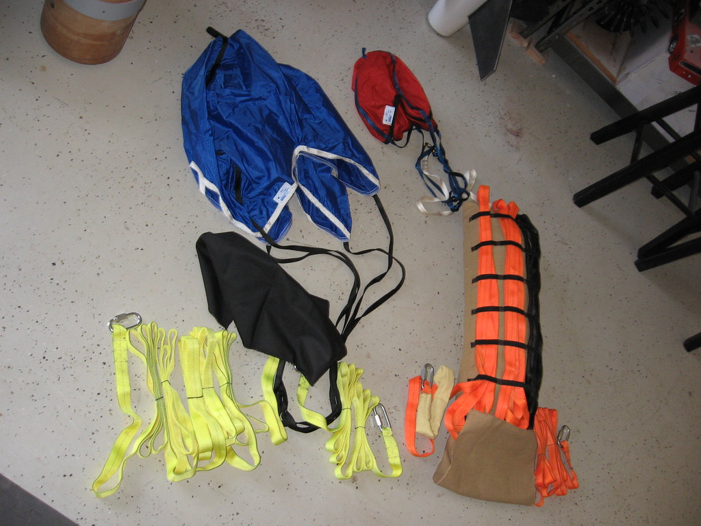
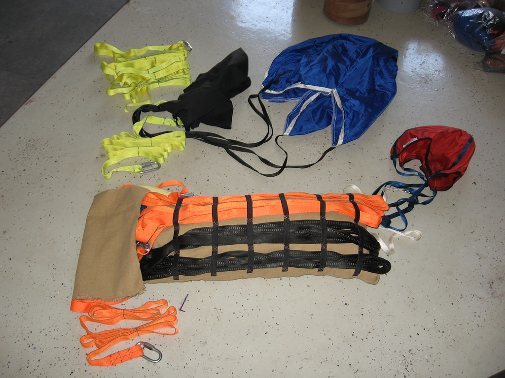
In any case here are snippets of the ground testing. Based on the calculation in 
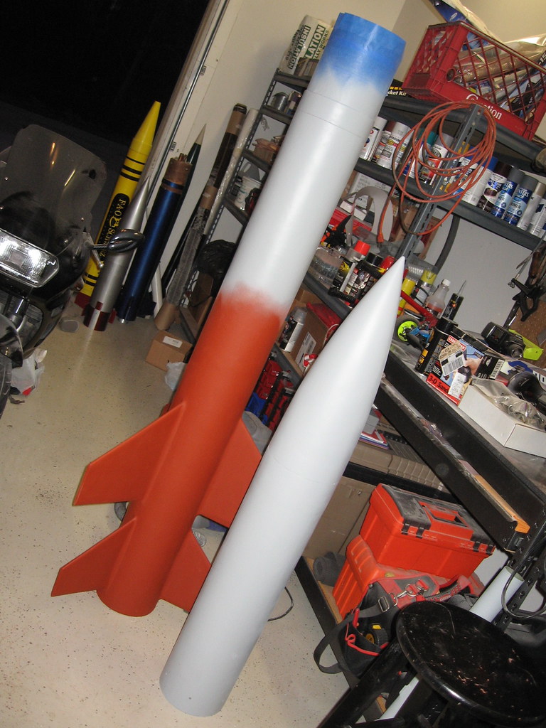
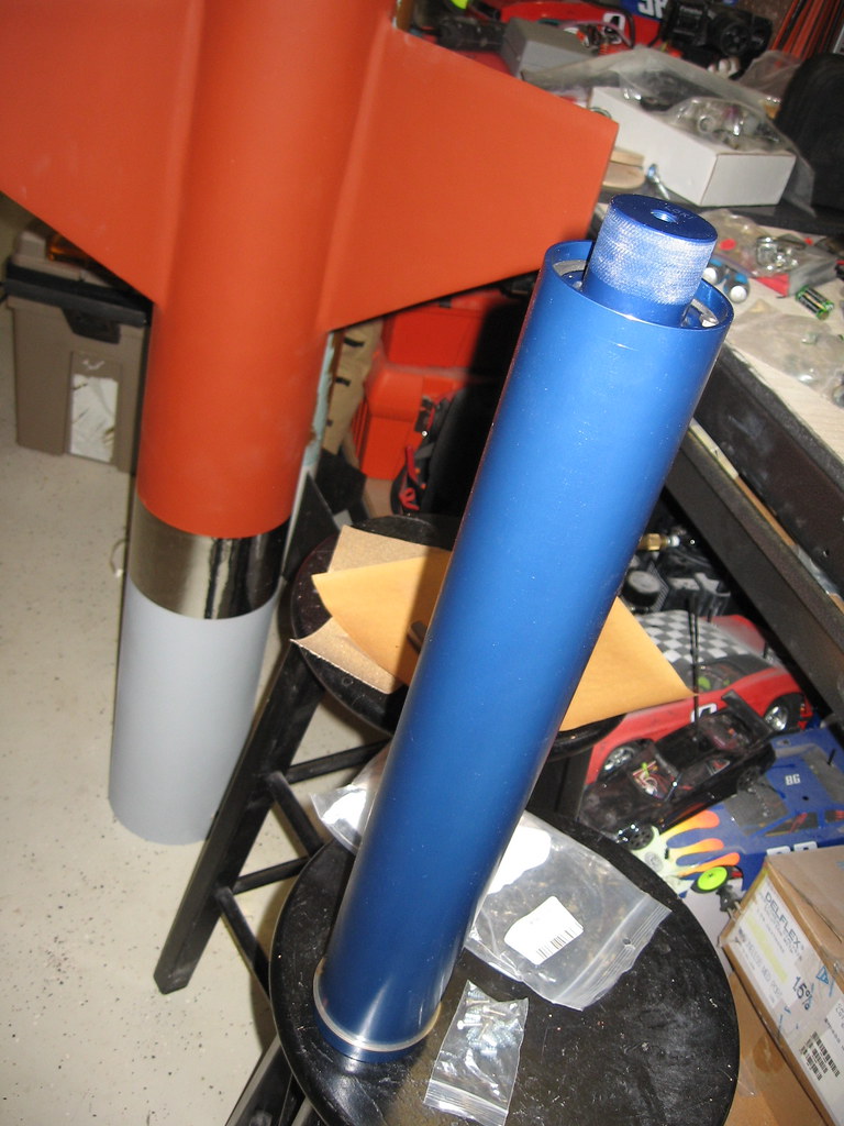
the design doc (page 14 of this older version of documentation), I was to use 4.5g and 2.25g of Triple 7 for the main and apogee charge respectively. For convenience sake with my measuring tools I just used 5.0g and 2.5g. As it turns out (and you'll see in the video) is that the main charge was great, the 2.5g "possibly" good. I say possibly because I made an error in set up and testing which I'll share after the video. But what you'll see in the video is a apogee charge of 4.0g and a minimal separation (not surprising given the weight of both sections on the stand, but also due the error in my set up). In any case, here's the test (Note: the ugly purple tape in the middle of the rocket is there to protect the chrome monocote during testing on the stand):

[YOUTUBE]PgsAJcItdBY[/YOUTUBE]

Looking at the still shot of the main separation from a different angle shows how well the spacing occurred. The nosecone is about 20 feet out, the pilot chute popped well away from the deployment bag; with the d-bag being a couple of feet from the airframe. So, all-in-all, I'm calling this good and will go with 5.0g main charge with 6.0g main backup charge.

4492003634_720f9f5930_b.jpg


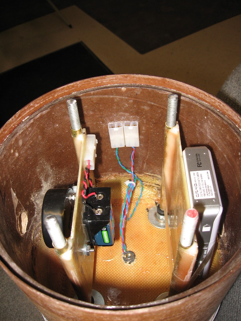
As is clear in the video, the apogee charge did not separate with as much vigor as the main event. I believe there is one big reason, but two other smaller reasons for this. First the smaller reasons... In my design document, I neglected just how full the main compartment would be and, conversely, just how sparsely filled the apogee compartment would be. Second (small reason) is that I also ignored the MMT. With the 76-3600 motor installed there is more than half of the 40" MMT left open. Thus both the above lead to the need for more force/pressurization.

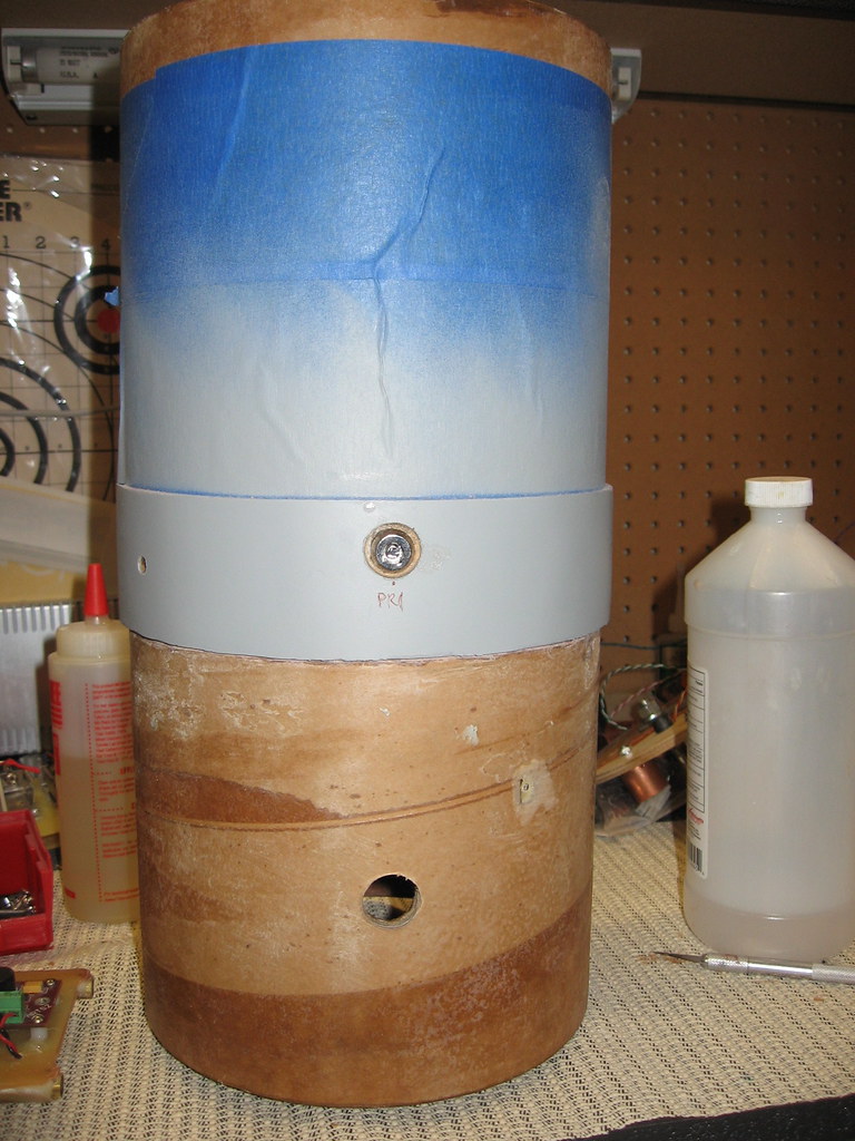
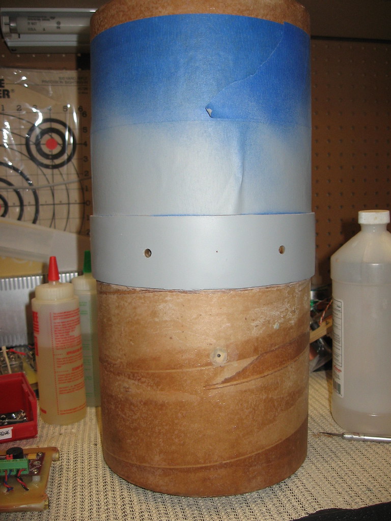
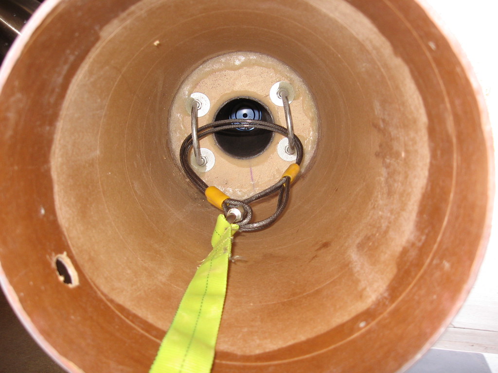
But the real (big) reason is my screwup. In setting up the test, I didn't have e-matches with leads long enough to thread through the aft section of the av-bay, the center access point and back out the vent holes. Actually I do have e-matches with leads long enough, but I didn't want to burn through my e-matches so I used some homemade initiators. In any case, dummy me, I just fished the leads through the camera window/hole in the bottom section of the av-bay thinking in my mind that the twist wires would just separate as the airframe separates. DUH! As can be seen in the picture below, upon separation the leads had to actually be pulled on the outside of the coupler and of course adding two 22 gauge wires between a coupler and a BT makes it tight as heck (as I verified afterwards)! Well the good news is that 4.0 grams is more than enough to achieve separation, in fact, in real life it will likely be a vigorous separation--that's O.K. Better safe than sorry, so I'll stick with the 4.

4491996542_377d098f0d_b.jpg
 
Last edited:
O.K., I think I have this worked out, but frankly I'm a novice at YouTube and I can't seem to get the quality from the upload that I have locally on my computer--don't know if its the resolution or the format or what (I'm certainly open to help and suggestions here)?

I suspect you just need to wait a while. Youtube encodes videos at different resolutions. 360, 480, 720, and 1080 (number refer to number of rows in the video). Youtube ususally makes the lower resolution videos available first, because the lower resolution videos do not take as long to encode.

Bob
 
Yes, they hold the ejection charge. Inside the copper caps fit a section of copper tubing that has an epoxy plug in the bottom. A picture of the copper tubing sections inserted in the caps is back on post #122 and in that same picture you can see the two other charge holders laying on the bench (the ones that fit in the fore bulkhead shown just to the right on the bench). In the bottom of the copper tubing a small hole is drilled (offset from center) in the epoxy plug. Then in the side of the copper cap a similar small hole is drilled. Through these two holes you thread your e-match leads and then attach them to the adjacent terminal strip. The BP is held directly in the copper tubing and is sealed per the attached diagram.

Can you tell me how you decided to go with Triple 7? I jut got some Pyrodex P and I wonder if Triple 7 would be better. Thanks.
 
I started using Triple Seven originally based on a recommendation from a person in California at the Los Altos Rod & Gun Club where my son and I used to go shoot. Triple Seven in testing is "more explosive" than Pyrodex P, but frankly, if done right, I think Pyrodex P will work fine. My advice: test, test and test again until you are absolutely sure you know how to make the charge work.

Can you tell me how you decided to go with Triple 7? I jut got some Pyrodex P and I wonder if Triple 7 would be better. Thanks.

t7-granular-comparison-test.gif
 
Spent about 30 minutes rechecking all settings on the altimeters. They're good to go. Then had a few extra minutes and built the Loki L1482 for this weekend's test flight.

4500501191_f96de04410_b.jpg


And now the motor's all loaded ready to go. If all goes as planned it'll fly on Saturday morning at Thunderstruck 2010.

4500501211_765cf1dbff_b.jpg
 
Spent about 30 minutes rechecking all settings on the altimeters. They're good to go. Then had a few extra minutes and built the Loki L1482 for this weekend's test flight.

And now the motor's all loaded ready to go. If all goes as planned it'll fly on Saturday morning at Thunderstruck 2010.

My guess is that you are quite eager to fly it, building the motor 3 days in advance and all! I know how you feel.
 
Spent about 30 minutes rechecking all settings on the altimeters. They're good to go. Then had a few extra minutes and built the Loki L1482 for this weekend's test flight.

I thought you were going to go for L3 at Thunderstruck. So if it isn't going to be this weekend then when are you going to go for it?
 
Well, yes and no. It's really more the schedule. Packed with work until Friday late and then going out with my wife that night before packing early Saturday morning to drive up. My wife is out right now, so just as soon get a few things pre-done.

My guess is that you are quite eager to fly it, building the motor 3 days in advance and all! I know how you feel.
 
Back
Top