Dynacom Tarantula

The Rocketry Forum

Help Support The Rocketry Forum:

This site may earn a commission from merchant affiliate links, including eBay, Amazon, and others.

ECayemberg

Well-Known Member
Joined
Jan 21, 2009
Messages
2,877
Reaction score
849
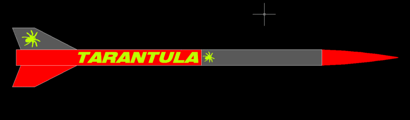
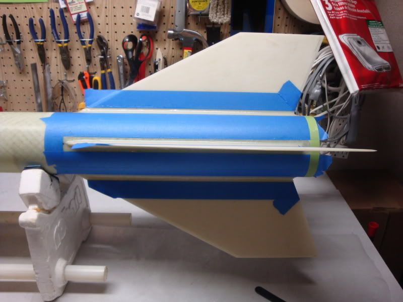
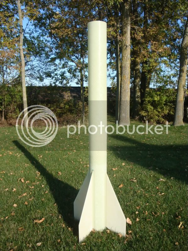
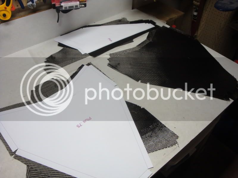
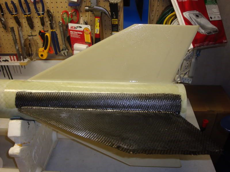
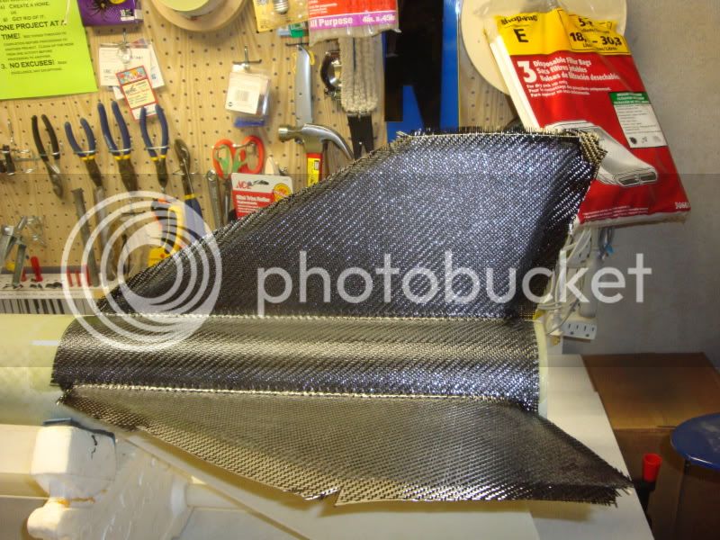
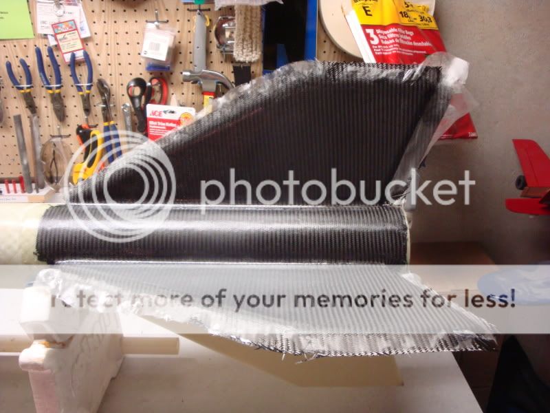
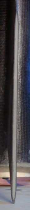
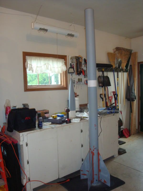
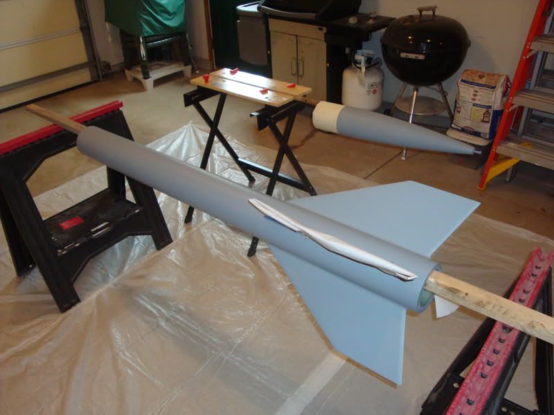
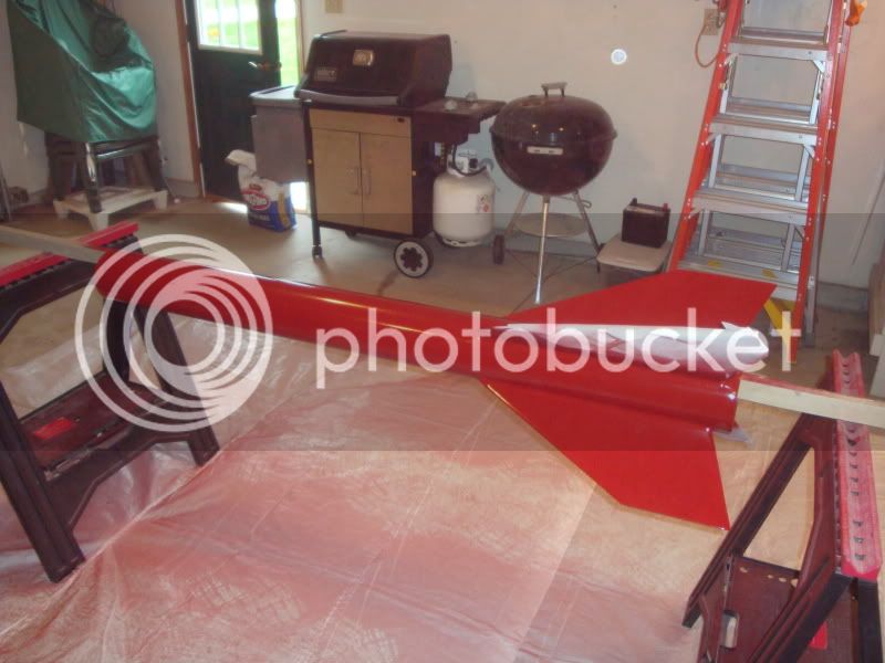
Time for a new addition to the fleet...one of the classics in my book...a Dynacom Tarantula. Well, it's actually a clone of the Tarantula although I'd happily purchase a true Tarantula if it was available.

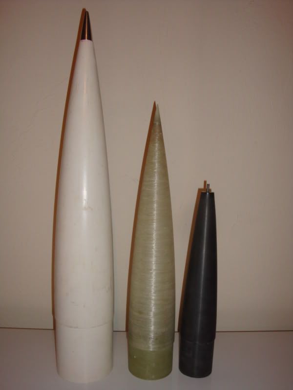
The Tarantula was designed as a 2 stager, and was available from Eric Haberman at Dynamic Composites, Inc., or Dynacom in the 90's until Eric ceased production somewhere around the turn of the millenium. Eric later produced three rockets of the same basic design under the name "Air-X". I'm fortunate enough to have the Air-X Delamar, which is the 4.1" version with a 3" mount.

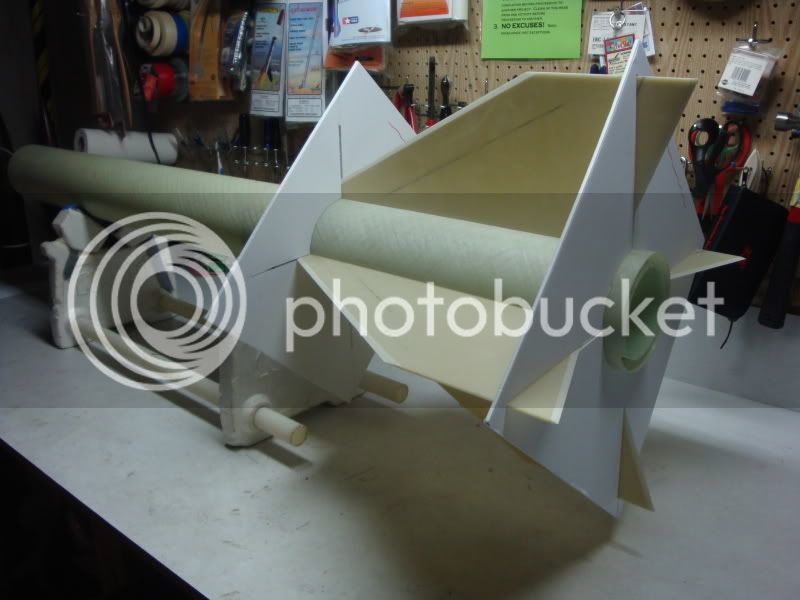
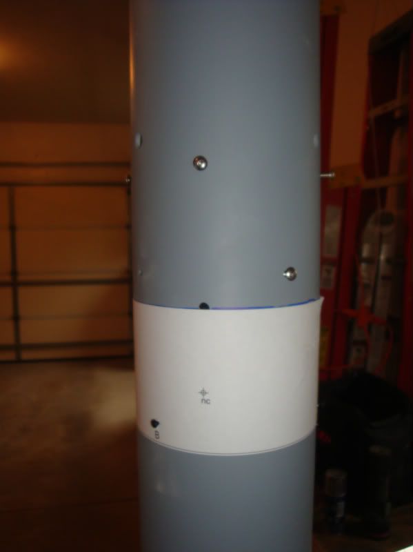
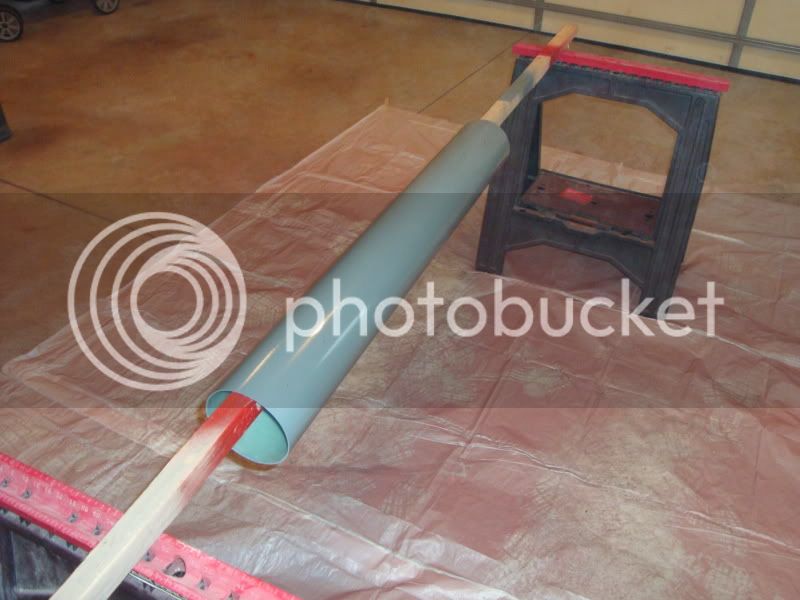
I picked up the parts for this rocket about two years ago, and am finally getting around to putting it all together. If all goes well, it will fly on an AMW N2800 White at Midwest Power over Halloween weekend this fall.

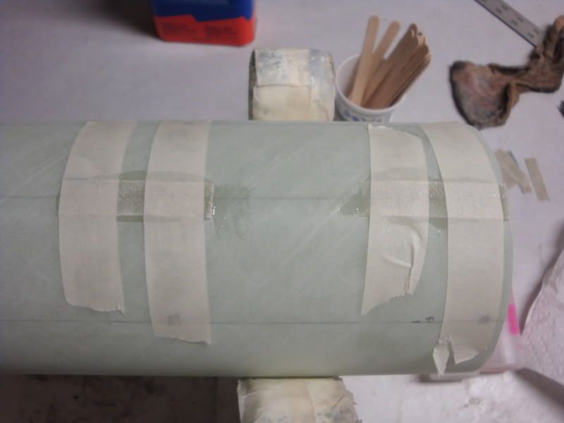
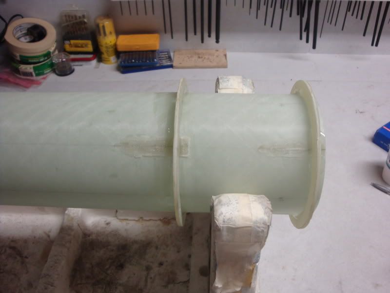
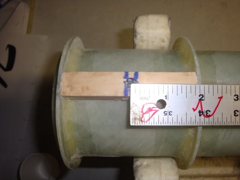
Let's get rolling. This build thread will be fairly concise, as time is short and projects are plentiful!

-Eric-
 
Nosecone: Part I:

I picked up the nosecone from the Wildman a few years back. I got a good price on it, as the tip was gone, some of the gelcoat cracked, and it was a good bit scuffed up. I was happy to get a deal, and happier to find a 5"1 ogive 5" cone that mimic'd the shape of the Dynacom cones.

First step was to clean up the tip of the cone. Rather than adding a epoxy/fiber/filler slurry to the tip, I figured this would be a good opportunity to share the aluminum tip from a Performance Rocketry Proline cone. Therefore, the tip of the 5" cone was chopped off at an appropriate location, a hole drilled in the now-flat surface of the tip, a 1/4"-28 bolt was threaded into the aluminum tip, then covered with epoxy, and shazam we have a nice new tip for the worn 5" cone.

This (not-so-great) photo shows (from Left to Right): Aluminum tipped 5" 5:1 ogive Performance Rocketry cone, 4" Dynacom/Air-X 5:1 ogive cone, and a 3" Proline cone with the robbed tip removed.
9-17-11048.jpg


-Eric-
 
Last edited:
Fins: Part I:

A 24"x36" sheet of .125" thick G-10/FR-4 was ordered from McMaster-Carr. A fin template was made, traced onto the sheet, and the fins were cut out using a jigsaw and a steady hand. All four fins were trued up using 80 grit and a sanding bar.

Here's a photo of a fin ready to be sent to the beveler:
9-17-11010.jpg


-Eric-
 
Tubes Cut

Next up was some minor tube cutting.

Motor Tube: A 48" long section of G12 airframe was cut in half: half goes to the Tarantula for the motor mount, while the other half goes to a 4" rocket needing zipper repair. The 24" motor mount is 6" shorter than the original Tarantula, but longer than the fin roots, so plenty long for me!

Lower Airframe: The original Tarantula airframe is a 62.12" length of beautifully wound filament fiberglass. My clone uses a 60" length of Performance Rocketry G-12 filament wound. No cutting necessary here!

Upper Airframe: Since the lower airframe was a bit shorter than the original, the upper airframe became a bit longer than the original. Therefore, a 48" airframe was cut down to 39".

Sorry, no photos. The first half of this week will be consumed by RX activities, so no further progress expected until later this week:)

-Eric-
 
ECayemberg said:
Here's a photo of a fin ready to be sent to the beveler:

Sent to? Is that a generic term for you doing it later, or is there a place you send your fins to be beveled?
 
Jeff, Giant Leap will bevel fins. Additionally, I have a buddy who will occasionally bevel fins for friends. In this case, the fins went to the friend for beveling, and he got a couple bucks for his troubles.

If there's one step that I just don't enjoy...it's beveling fins. When I use thicker glass or carbon fins on projects, I leave the beveling up to the pro's!

-Eric-
 
Do you happen to have rocksim files for the dynacom kits that you would be willing to share? I always wanted a python but by the time I got old enough to make the money to purchase one he had gone out of buisiness!
 
cm: Sorry, I do not have RockSim files for any of the Dynacom birds. I only have the paper/pdf copies of the Tarantula and Delamar. John Coker has a page for the Python, and VernK has some detailed pages on other Dynacom kits

Fins are beveled and look great! The tight fitting coupler for the upper-lower airframe joint was sanded to fit. Fin slots are marked and should be cut today; motor mount and fin tacking will hopefully occur this weekend.

-Eric-
 
Needless to say, this is a project that I am eagerly awaiting more pics of.

I'd love to clone a Dynacom kit at some point.
 
Update time! Lots of work has occurred behind the scenes prepping the rocket for assembly (IE: cutting, sanding, roughing up, slotting, beveling, etc.).

Lets finally add some epoxy to this thing!

Motor Mount
The nicely cut G-10 centering rings were loose on the motor mount. A solution was to cut some thin home-made G-10 into 1/2" x 2" strips:
roc9-28-11008.jpg


These strips were roughed up via dremel and epoxied to the motor tube spaced 90 degrees apart at the centering ring locations. (Yes, the strips are not aligned perfectly...no it doesn't matter:))
9-28-11071.jpg


The strips were then ground down until the centering rings fit well. The two forward centering rings were then tacked in place using Z-poxy.
9-28-11073.jpg
 
Rail Button Hardpoints

1/4" tee nuts were installed into to 3-3/4" long hardwood blocks which were then epoxied onto the motor mount assembly. Locations were noted before installing the motor mount, although the blue marker is visible through the transparent G-12 airframe.
9-28-11077.jpg


Filleting

I may be out of sequence here...but the forward centering rings and the rail mounts were filleted with the typical West 105>205/206 mix with milled fiber (for strength/decreased brittleness) and cabosil (for consistency, fillet-a-bility:D). Before filleting, the areas to be filleted were treated with a wiping of virgin (non-filled) West epoxy.

Typical slurry ingredients:
9-28-11074.jpg


Motor mount assembly ready for installation into the lower airframe:
9-28-11082.jpg


The motor mount assembly was epoxied into the lower airframe using the same epoxy process as noted above. At this time, only the forward two centering rings received epoxy. The aft centering ring was used, but not epoxied, to properly align the motor mount assembly. (Note, this is a deviation from the Dynacom method where the fincan assembly is created outside of the airframe, then slid into place).

Dry Fit
After the epoxy dried, fin alignment guides were created and the fins were dry fit in place.
roc9-28-11025.jpg


This takes us to last night and three realizations:

1. The fins are big. I already knew this, but once they're added to the airframe; they become that much larger! Tip-to-tip reinforcement will help minimize flutter.
2. I'm finally building the Tarantula I've longed to own/fly since the early 90's! Woo-hoo!
3. The fin alignment guides and fin slots hold the fins in place well enough that I can use one batch of slower curing epoxy to tack all four fins at once. I prefer to do this over one batch of fast cure epoxy for each fin...if and only if the fins stay in place without too much help.

-Eric-
 
Last edited:
If I'm able, I'll tack the fins tonight. Otherwise, it will have to wait until Monday, as we leave early a.m. Friday for a wedding on the other side of the state.

One last photo for now. IF there is time to apply paint and decals before the temps. drop off and/or Midwest Power takes place, the planned paint and trim scheme is below:
trant.gif


-Eric-
 
Looks awesome! I really love that design, but you are right, that's a lot of fins! Makes me wish I had scratched that design instead of building a Competitor 5...
 
Fortunately, work has progressed on the Tarantula at an acceptable, but not blistering pace. Unfortunately, the camera has not kept up with the build rate. Let's play a little catch up.

The fins were tacked in place using the typical epoxy slurry. They were allowed to dry for 24 hours.

External fillets were then layed. The area was taped off to minimize excess epoxy gooberage.
8-25-11062.jpg


The fillets dried for a day or so, then were taken outside to be roughed up for tip-to-tip lamination. Ideally, the layup would be done before the fillets set up, allowing for a chemical bond. My schedule did not allow for this, so mechanical bond to roughed up surface will have to do.

After the fillets were sanded a bit, the booster posed on the lawn for a quick snapshot.
8-25-11073-1.jpg


In the meantime, internal fillets were poured. The pourable mix was West 105/205, milled fiber, and chopped (~1/2") carbon tow. Fillets were poured, four at a time. Each fin to motor mount and fin to airframe joint received a fillet: 16 total.
 
Last edited:
Fin Patterns
Next up is/was fin can lamination. Fin patterns were drawn up, printed out, and cut out to size. Three patterns were made for the four layers of cloth: one each of the actual fin can dimensions plus 1/2", 3/4", and 1" overhang on all sides.

Cloth Cut
The cloth for the fincan is three layers of 5.7oz harness weave carbon fiber and one layer of .6oz fine weave E-glass for the sanding veil. It may be a bit of overkill, but these fins flex a lot without the layup and the sweep on the trailing edge, as well as large tip chord make the fin design susceptible to flutter. Regardless, the 20 pieces of cloth were cut using an Olfa mat and roller blade.
8-25-11194.jpg


Layup
Just add epoxy! The first layer (1/2" overhang) has the fiber running parallel/perpendicular to the trailing edge of the fins. The intent here is to provide the longest length of fiber possible running along the aft sweep of the fin's trailing edge. In order achieve this angle for each opposing fin, the fabric stops at the midpoint between the two fins.
8-25-11197.jpg


The second layer (3/4" overhang) has the fibers running parallel/perpendicular to the airframe. This is a more traditional tip to tip fiber direction and should reduce the twisting moment of the tip chord, as well as minimizing deflection along the span of the fin.
8-25-11198.jpg


The third layer (1" overhang) has the fibers running at 45 degree angle(s) to the direction of flight. This provides resistance to twisting along the leading edge of the fins.

The fourth layer (1"+ overhang) adds no epoxy and little weight. The .6oz E glass is there to simply smooth the surface and protect the carbon when sanding. This provides a surface that is "pinhole" free and requires little more than a few coats of primer to be paint ready.

Here, the 3rd and 4th layers have been applied.
8-25-11200.jpg


The layups for the remaining three sides will be identical and will be completed by Thursday of this week. Then it's time to construct the E-bay and apply some primer!

-Eric-
 
Eric, tell me about the successive overhang lengths. Is this to help maintain the fin bevel? I ask because I typically stagger layers inside the fin outline when I do multiple layers to get a bit of an airfoil effect (although, if you are worried about flutter, I can see the benefit of as stiff a leading edge as possible).
 
Eric, tell me about the successive overhang lengths. Is this to help maintain the fin bevel? I ask because I typically stagger layers inside the fin outline when I do multiple layers to get a bit of an airfoil effect (although, if you are worried about flutter, I can see the benefit of as stiff a leading edge as possible).

I am assuming too, it helps smooth the edges at the fore end of the fincan on the main tube. If all four layers ended at the same point, you'd have one hell of a ridge there.
 
Tim, Dan pretty much nailed it.

I have done several tapered layups as you mention with good success. I have however gravitated towards full span layups (with overhangs) for a few reasons.

A)Smooth the transition on the airframe at/near the leading and trailing edge of the fins. Less filler, less fuss:)
B)Allow gravity to help drape the fabric overhangs down at the edges of the fins. The fabric is relatively stiff and the little extra length helps.
C)The extra material is used to ensure a seal to the edges and also make sure good straight fiber exists at the edges (if I cut it exact, frays, bumps, rolling of fiber would make for a less uniform and thicker edge). Furthermore, as you know, the harness weave fabric shifts around a bit, so I like to ensure I'm not short on material if a slight misalignment occurs.
D) I've always considered it good practice to have each successive layer completely cover the prior layer...to minimize the probability of delamination.
E) I like the ability to trim all the layers at once at the edges of the fins. It becomes fairly easy to make a razor sharp edge (or slightly rounded), and the fin surfaces are flat...prime it and paint it!

I will admit that the successively larger overhangs doesn't matter much along the edges of the fins, however it gives me piece of mind that each layer will completely cover the prior layer, and the largest overhangs will pull down the layers underneath.

I think that's my logic; right, wrong, or indifferent:cyclops:

-Eric-
 
Last edited:
Any progress on the altimeter bay? I've been curious what units you'll be using and how you have it laid out. I know in my Competitor 5's bay, there's an overabundance of room for my MAWD and ARTS2.

Looks awesome!
 
Thanks Dan. I plan to install an ARTS2 and Adept22 in the E-bay. I have a MAWD that would be a likely candidate, but it's going to be riding in the 11.5" V-2 again at Midwest Power. Electronics and prep are next week's job!

The fincan layups are complete. The aft centering ring will be installed today or tomorrow, coupler fastened to the payload airframe tomorrow. Priming, sanding, filling, etc. to begin this weekend.

-Eric-
 
Thanks Justin! Lookin' forward to seeing you and the gang in...a week!

Whoa, only a week 'til Midwest Power kicks off. I've been busy, which is why the updates have been non-existant. After completing the tip to tip lamination, the edges were trimmed and rough sanded.

Here's a quick snap shot of the tip chord sandwich.
10-18-11284-1.jpg


After trimming, much sanding, filling, and priming has occurred. Oh, and more sanding. Some more filling. And more sanding. Gotta love the sanding:rolleyes: Somewhere along the line, lots of holes have been drilled as well; altimeter vent holes, airframe vent holes, shear pin holes, rail button holes, and e-bay-to-payload section fastener holes.

Here, we have the payload to booster airframe joint. Shear pin holes are being drilled; the rest of the holes for the E-bay are already complete.
10-18-11302-1.jpg


In order to shear pin, both sections must be mated together in alignment; therefore a decent photo opp. of the two lower sections together. The garage ceiling is 9.5 feet; the Tarantula minus nosecone occupies most of that height. At this stage, two coats of primer (and filler/sanding) have been completed on the payload section; one coat of primer (and filler/sanding) are on the booster.
10-18-11303-1.jpg


This takes us to last night; and the most beautiful/ugly sight that I love to see on a build...the camoflage of the structure, primer, and filler all ready for a final topcoat of primer prior to paint.

Here we have one side nearly ready for final primer...had to add a bit of glazing at the trailing edge. After sanding the bit o' glazing, final primer was applied.
10-18-11305.jpg


The Tarantula is finally ready for paint; although I can't say that the weather is paint friendly. Atrocious weather this week has provided 40mph winds, rain, and temps in the 40's. That said, if all goes to plan, base coat paint will be applied today (in the garage!)

Still to come: E-bay and nosecone construction.

-Eric-
 
Looks awesome! I know you flew the classic M1939 in your V2...but I feel this model needs it as well.

Maybe an N10,000 as well to prove your fincan is rock solid...
 
The Tarantula is finally ready for paint; although I can't say that the weather is paint friendly. Atrocious weather this week has provided 40mph winds, rain, and temps in the 40's. That said, if all goes to plan, base coat paint will be applied today (in the garage!)

Looks like we may have a window from tomorrow morning through Sunday late afternoon--at least that's what I'm shooting for. Applying final primer-sealer on two birds this afternoon. Base coat tomorrow morning. First colors Saturday morning. Secondary colors Sunday afternoon. Decals Monday and then Future on Tuesday evening (which can be done inside).
 
Last edited:
Looks awesome! I know you flew the classic M1939 in your V2...but I feel this model needs it as well.

Maybe an N10,000 as well to prove your fincan is rock solid...

Thanks Dan! We'll be flying an M1939 clone at Midwest Power as well...just with a bit more average thrust. While it won't be in the Tarantula, it will be in another 5" glass rocket!

I've had an AMW N2800 White Wolf for some time, initially intended for the 11.5" dia. Nike Smoke...the motor should give it a nice ride! The N10,000 certainly would test the fin stiffness! If the rocket survives the initial flight, we'll see what we throw at it next!

-Eric-
 
Looks like we may have a window from tomorrow morning through Sunday late afternoon--at least that's what I'm shooting for. Applying final primer-sealer on two birds this afternoon. Base coat tomorrow morning. First colors Saturday morning. Secondary colors Sunday afternoon. Decals Monday and then Future on Tuesday evening (which can be done inside).

Tight schedule Tim! Hope the weather cooperates and best of luck with all the paint. I did get the painting done yesterday, but it was in the garage. Despite wearing a mask, I inhaled more paint fumes yesterday than I care to. Given the option, I'd much rather paint outside! One week to go!

-Eric-
 
Time to paint this arachnid.

Due to the inclement weather outside, painting was relegated to the garage. Outside air temps were in the low-to-mid 40's, with rain and wind. The garage temp was in the low 50's when setup began. The new space heater was turned on, cranked up, and the floor was covered with overspray plastic. The lower airframe and nosecone were skewered and readied for red paint. Here's the setup:
10-18-11308.jpg


Paint used was Duplicolor Engine Enamel. I like Duplicolor paints, and the Engine Enamel line is their current best value offering...largest volume for the lowest price (at least locally for me anyway). The heat resistance on the fins can't hurt either, should we go for a speedy attempt at some point.

I was able to get the temperature in the garage up to 58 degrees prior to starting. Three coats were applied to the nose and airframe. Fumes abound, although the doors were partially opened and the rediculous wind allowed for a somewhat effective exhaust system. The nose got it's third and final coat first, so it was moved to the basement for some warmer dry time. Here, the booster has received it's third and final coat, and is awaiting relocation to a warmer climate. Can you see the haze?:eyepop:
10-18-11310.jpg


With all the red out of the way, the upper airframe was prepped to receive it's gray paint. It was again skewered, and three coats applied. After the final coat, it degassed in the garage for a few minutes, and then took the quick trip to the basement to continue it's cure cycle.

Payload kabob:
10-18-11312.jpg


Saturday or Sunday will be the day for applying gray paint to the two fins that were taped off from the red paint.
 
Back
Top