Rail buttons go at Center of Gravity or Center of Pressure?

The Rocketry Forum

Help Support The Rocketry Forum:

This site may earn a commission from merchant affiliate links, including eBay, Amazon, and others.

Underdog

Well-Known Member
Joined
Jul 5, 2016
Messages
119
Reaction score
11
The Open Rocket Simulator gives be "Center of Gravity" and a "Center of Pressure."
Where should I mount the forward rail button on this Estes Super Big Bertha? According to Open Rocket the CP is 16 cm (6 inches) aft of the CG (depending on the motor).
It weighs 10.5 ounces without the motor.
center of gra.JPG
center of prss.JPG
 
I usually do one button just above aft end (rail button into CR or additional backer material glued to aft CR), and one near CG as CR's or ability to install backer allow.

Hope that helps!
 
Old rule of thumb. 1 caliber below CG.
On "Open Rocket" the CG moves around with different motors. Do I use the heaviest motor or the lighest motor as the reference for CG?
Is "1 caliber" equal to the width of the body tube?
 
Yes, One Caliber is the same as a single body tube diameter. Put the railbutton at the CG you are most likely to fly the most motors at, the variance between heavier and lighter motors will have little effect on it. My rail buttons are usually placed at/near the bottom of the rocket and then as close to the CG as convenient ( for whatever reason eg ease of placement, aesthetics, solid backing, etc).
On "Open Rocket" the CG moves around with different motors. Do I use the heaviest motor or the lighest motor as the reference for CG?
Is "1 caliber" equal to the width of the body tube?
 
My Rail Button placement has no correlation to my CP or CG. However both CP & CG are marked on my rockets. On an average mine are in the bottom CR and approximately 1/3 up. Its better to have a secure! RB than anything else.
 
So the "center of pressure" does not really seem to matter when placing rail buttons? The further aft I place the top rail button, the longer the rocket is in contact with the rail (that should be a good thing).
 
I usually try to put the upper button reasonably close to the CG. That means when the button leaves the rail the center of mass is traveling directly in line with the launch rail.

I try to put the other button as far back as practicable. That keeps the top pointing in the right direction (remember the CG is already traveling on my intended path, and the rocket will rotate around that point naturally) for the longest time possible.

I have not analysed the sensitivities of this, but I expect the gains in doing it this way are of very low-order (due to small angles involved) effects for most flights in reality, so don't get too hung up on placement. That's my $0.02 worth.
 
The center of pressure isn't really relevant on the rail, it only applies once the rocket is in free flight. What you want is to make sure the rocket is under the control of the rail buttons until stable velocity is achieved and the fins can take over ensuring straight flight. A very important part of rail button placement is making sure the rocket does not bind due to wind, CG issues, or under thrust. They need to be far enough apart to avoid a short moment arm that could lead to binding but no so far that you loose rail length. Of course you can always use a longer rail if needed.


Tony
Well this gives me lots of flexibility. I like having options. The wall on the body tube of the Estes Super Big Bertha is pretty thin. If I could place the upper button on the coupler joint (halfway up) that would provide a better/more secure grip for the rail button screw. The tube is twice as thick at this location.
 
Only one club I know of has an issue with those guides, and its my personal observation that not allowing them is a club preference with no actual proof they actually cause excessive wear to the rail. The ACME rail guides do have to be perfectly in line or rail binding can occur, they also can pop off if the guide comes under any side loading as its put on the rail (and its only secured with epoxy, and no screws).
You can also go with Giant Leap's Acme Conformal[emoji2400] Rail Guides, Some people don't like the metal on metal aspect of them but I've used them for years and never! had any issues.
 
Basically user error, care should be taken with any type of rail guide. I've seen people attach a rail button straight into a paper tube with a spot of CA... Needless to say that's not the correct way to install them. What I did for these guides was use 80 grit on there underside, peel the glass off a paper tube then drill 2-3 tiny holes in the BT and attach with JB Weld. I let the JB mushroom out a tad on the inside of the BT. Never had one pop off yet.
 
Last edited:
CP does not matter at all for locating an upper lug.

When I'm using two lugs (whether for a round rod or for a rail), I put the upper lug at a good distance above the CG, unless the model is super-tall and the CG is VERY far from the tail. This reduces binding issues, and leverage forces trying to pry the upper lug off. It does shorten the total distance the model travels before the top lug leaves the rod/rail, but for some models that does not matter, and for others I use a longer rod or long-enough rail.

Bottom line, it's a bit more of a proportion to the length of the model thing, than a CG thing. But that would vary between say a Mean Machine, Big Bertha, and Baby Bertha using two lugs, all the same diameter, different CG locations relative to length.

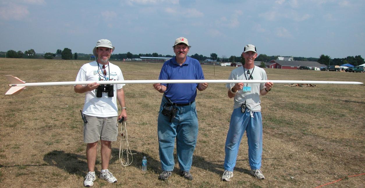
An extreme example in this image of our team's 14.75 foot long G Superroc (2 E6's and one F10 clustered, BT-60 tubing with very long couplers inside) at NARAM-49. If the top lug was at the CG, it would have been about where Terrill Willard (person on left) is, maybe a bit to the right. Leaving a lot of the model hanging off the rail unsupported, inviting disaster. Since we used a 12 foot rail (two 6 footers joined), it actually had three lugs (Plastruct "H" beam which is my preference for easy sliding rail lugs), the top one at about 10-11 feet up to help support the upper section, middle lug at about 5 feet from the tail (well above the CG), and bottom lug at the... bottom. Alignment marks were made on the tubes to be sure the lugs lined up when assembled.

DSCN0033.JPG
 
Last edited:
Back
Top