


Joe Rocket 97
Well-Known Member
- Joined
- Jun 29, 2018
- Messages
- 190
- Reaction score
- 51
Now that's creative! Was that a 5x54 mm Motor mount set up? Can you share a picture or two how you did it?
Now that's creative! Was that a 5x54 mm Motor mount set up? Can you share a picture or two how you did it?
That may be the route I may take alsothis is a custom single 54 that I had them make for me cuz I'm not going to fly clusters.
3.1” Tower Assembly
Summary of this Section: Let’s face it: no Saturn model looks right without the tower/capsule on top! What we came up with here is a compromise between functionality, survivability, and scale looks. The prototype survived landing nose down on a frozen lake bed unscathed! And we think it looks pretty good too!
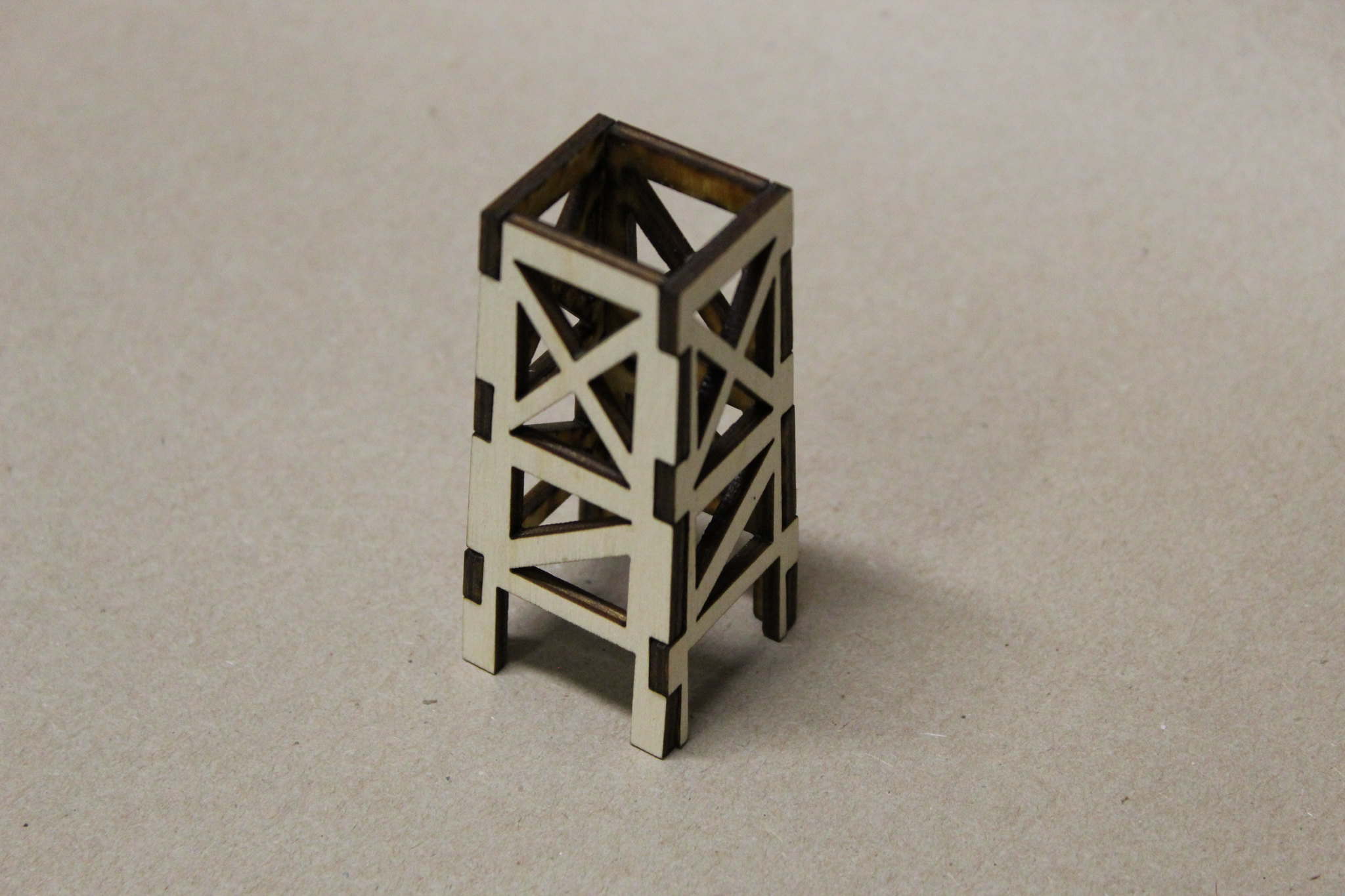
The tower is interlocking laser cut plywood.
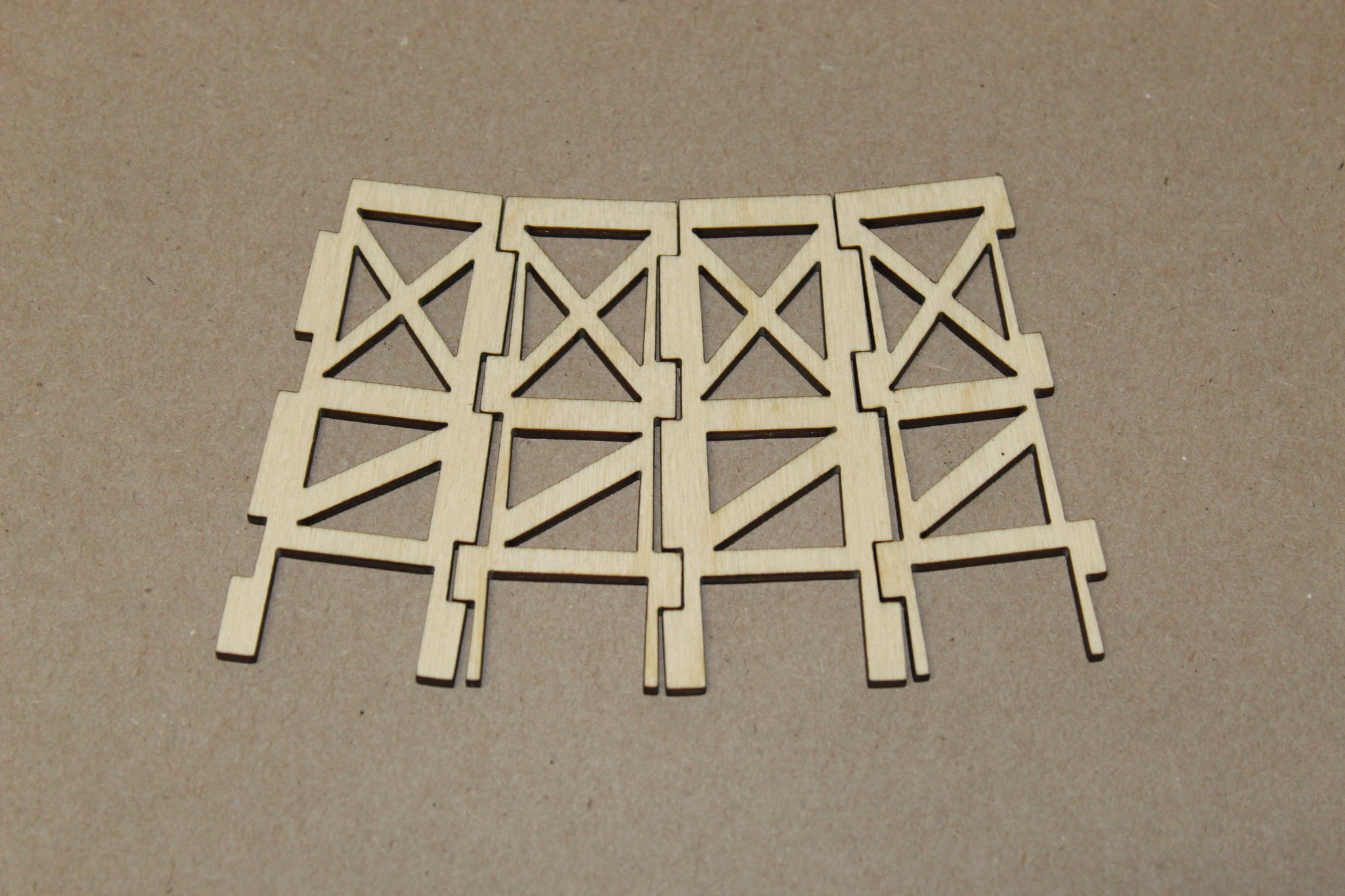
Glue together using wood glue, CA, or even epoxy.
Glue the three small rings together. Make sure to keep them centered (or you’ll have to re-drill the ½” hole in the center after). Glue atop the tower.
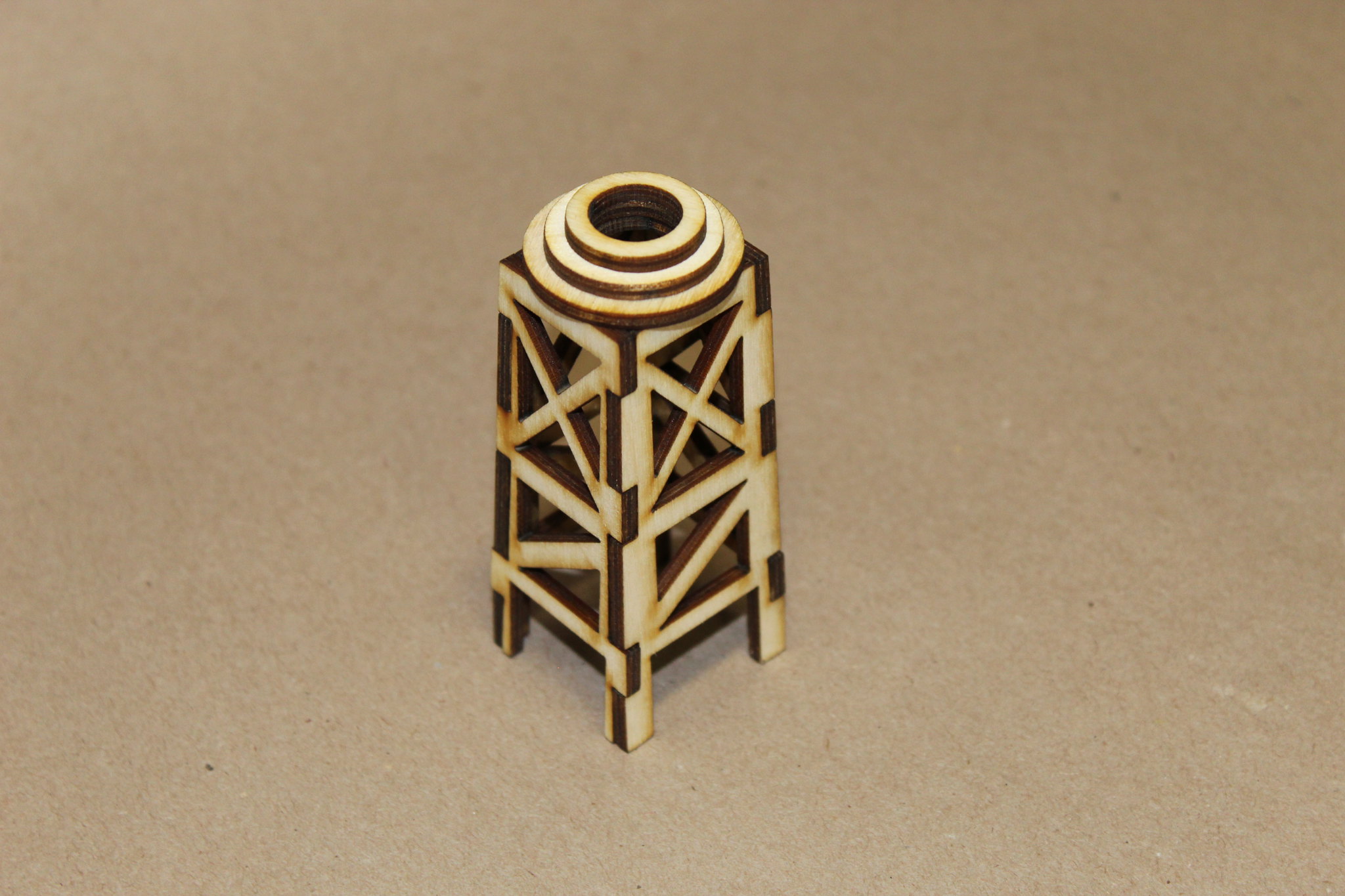
Fill the voids in between the rings with your favorite putty, and sand smooth, if desired. I really like the smelly spot fillers for this; or use Elmer’s CWF, or Superfil; whatever floats your boat! No photos of this step.
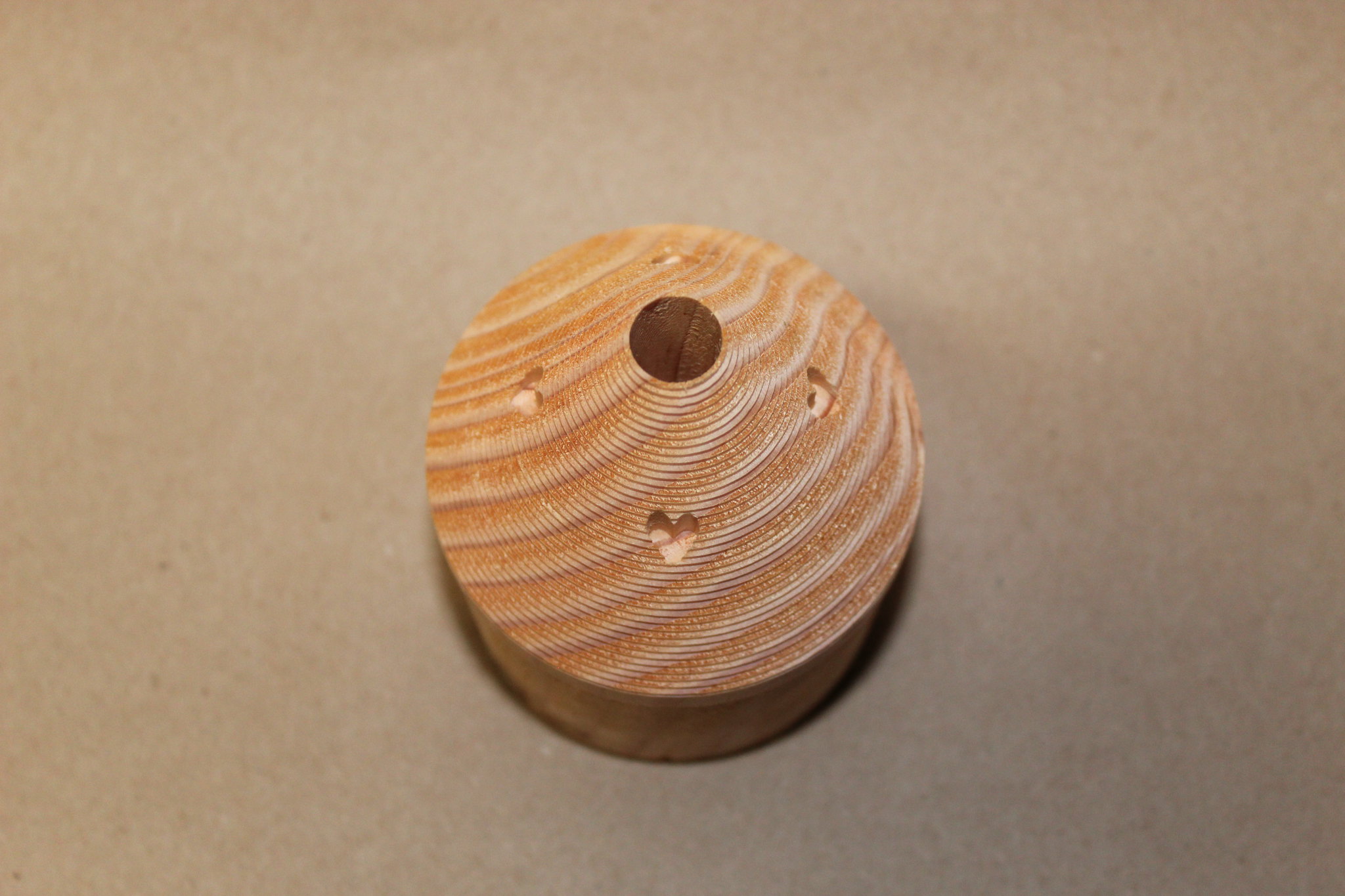
Fill and/or sand your capsule as desired. The machining process leaves ridges that may be filled in, sanded down, or your favorite combo of both. I chose to sand the prototype down. Pre-sanding photo:
Marry the tower to the capsule using your favorite flavor of glue. Those pre-cut slots are the bomb!
Glue in the ½” dowel, leaving the proper amount exposed. I forget the exact amount…somebody remind me to come back and edit this with the correct length!
Finish as desired with filler, sanding, priming, and painting. Pre-paint, pre-production example (I was in a bit of a hurry; the production version is a lot nicer!):
When completed to your satisfaction, test fit, and epoxy into top of 3.1” airframe tube. With access to the inside of the 3.1” tube from the bottom end, I can’t think of a reason not to permanently epoxy the capsule assembly in place.
Congratulations, you just completed the functional top half of a monster Saturn V!
Question for all of you building this LOC SV... how are you setting up recovery? looking at this kit, i believe it may be difficult to have the nosecone/tower come down with its own separate chute in a sling (aka the old estes kits or the apogee).. are you keeping the entire upper air section in one piece and just separating in the middle? given the 3-5lbs of weight needed in the nose (depending on config), certainly the escape tower and nose receive a bit of stress during a nose-down impact... alternatively could leave the escape tower off and only have it for display....
I'm trying to decide this also. I was originally going with single deploy but i worry about the nose getting damaged. Now I'm setting mine up for dual deploy. Also thinking about having the nose come down under its own chute at 500' or so. Im not sure if that would be better or not. I hope others post some ideas.Question for all of you building this LOC SV... how are you setting up recovery? looking at this kit, i believe it may be difficult to have the nosecone/tower come down with its own separate chute in a sling (aka the old estes kits or the apogee).. are you keeping the entire upper air section in one piece and just separating in the middle? given the 3-5lbs of weight needed in the nose (depending on config), certainly the escape tower and nose receive a bit of stress during a nose-down impact... alternatively could leave the escape tower off and only have it for display....
I don't think anyone would fail you for a broken tower as long as the rocket recovered under chutes and altimeters fired and separated according to flight plans. After all the rocket would still be structurally sound without the tower. You could also leave it off.I’ll have to figure out the tower during recovery problem as well. I have a really sick thought in my head about shoving an M1297 in this thing for an L3 attempt, and would hate to fail it due to a broken tower...

How long will this kit be available? I want to get a big Saturn V but I can't afford it this year with my L3. Any idea if you will continue selling this kit?

I ordered mine maybe 2 weeks ago, and was told I got one of ~3 that were left. Based on hearing that, I am assuming they are not planning on any additional runs of the kit and that it will soon be sold out if it isn't already. Sorry to be the bearer of bad news.
The following is a photo pictorial with brief descriptions of the assembly of the Loc Custom 7.67" Saturn V intended to guide the builder through the assembly process. It is expected that the builder of this kit has prior knowledge and experience with high power rocketry construction.
So welcome aboard, happy 50th Anniversary of the Apollo 11 flight, and enjoy the flight!
The model shown in the photos is the prototype...a quick built proof of concept project. The actual production model parts will vary slightly from shown (IE: you won't get the ugly duckling transition shown in the next few photos
Upper 7.67” Airframe Assembly
Summary of this Section: the booster section consists of a 30" length of 7.675" OD airframe. This section, essentially a complex nose cone, sits atop the booster section.
Begin by installing a U-Bolt, and then epoxying a bulk plate into one end of the 7.5” coupler. Epoxy the Stiffy coupler inside the coupler as well. Fillet both sides of the bulk plate.
*Note*: if the builder chooses to build their Saturn V with electronics based dual deployment, they may choose to build this coupler as an Electronics bay.
Make marks around the perimeter of the 5.54” tube 9.92” from one end of the tube (10” is fine, just be consistent!). This is where the top of the lower transition will sit.
Slide the lower transition onto the 5.54” tube. Two 5.54” to 7.5” centering rings will be glued to the 5.54” tube below the transition as shown. Square up the lower transition using the top centering ring, 7.67” airframe, etc. Mark the airframe and scuff the tube as necessary.
Prepare to epoxy top ring and transition in place
Epoxy it all together! The builder may choose to use a slower setting epoxy in order to allow time to ensure proper alignment of the transition. No pressure, but don't screw it up!
-base of the transition where it meets the top edge of the centering ring
-top of the transition where it meets the 5.54” airframe
-Fore and aft edges of the top centering ring where it meets the 5.54” airframe
-Fore and aft edges of the bottom centering ring where it meets the 5.54” airframe
Clean up any excess epoxy, ensure proper alignment (use 7.67” tube if necessary), set aside to dry.
Epoxy lower centering ring 1/4" up from the end of the 5.54" tube. Fillet the ring-to-5.54" tube joints, set aside to dry, and admire your good work.
That is one awesome launch pic!Here was my Anniversary flight yesterday of the Loc kit on a Loki K960. The beast weighed in at 25lbs and went 2272 ft with perfect dual deploy recovery! Gotta love that Loki flame!
View attachment 389084
Enter your email address to join: