98mm min dia high altitude deployment

The Rocketry Forum

Help Support The Rocketry Forum:

This site may earn a commission from merchant affiliate links, including eBay, Amazon, and others.

tfish

Well-Known Member
TRF Supporter
Joined
Dec 7, 2009
Messages
3,531
Reaction score
2,785
It's been awhile since I've done a build thread of sorts. I will be combining a couple of topics (which go together) 98mm min dia rocket and high altitude deployments.

The rocket is really nothing fancy. It's made mostly from pieces I've been gathering and even some stuff from my local junkyard. The design is what I call an "AeroPac Sport flyer" I'm not trying to be funny or slam other people. I'm lucky in that Black Rock is my home field. With that being said I've seen a lot of record altitude attempts. Mostly just attempts. The two biggest issues are construction not up to the task or poor design. Most of the stuff I've learned has been at other peoples expense. And lots of my own thrown in for good measure.
I'll start with design. Some attempts go unstable fairly quickly. I call these rockets glass slippers. If everything is just right they work and get some amazing altitudes. When they don't work they disintegrate. These rockets usually have one or both of the following issues. The fins only have 1 caliber of span and the rockets stability margin is 1 caliber or slightly more.
I like my AeroPac Sport flyers to have fin spans of 1.1 calibers. This seems enough to keep some fin in clean enough air to over come any mishaps.

Below is 3" min dia AeroPac Sport flyer flying on a motor with 40" of propellant.


That little wiggle was at mach 1.76

I owe it's ability to recover to 3 things. Fins with simi spans of 1.1 calibers, on the pad stability margin of 2.5 and construction methods up to the task.

I like flying these types of rockets with 2.5 calibers of stability or even more. I'm a simple guy and look at the CP and CG as a couple of guys running towards each other. They both need to stop but sometimes one of them or even both of them can't stop in time and they collide. I'm not sure if this is technically what's happening but it works in my mind.

So now design and construction. Fin shape has a lot to do with flutter. You can either use a well designed fin or over build them to work. I've only used .125: G10 three times in all my rockets. Most of the time it's .097"
This rocket has .125" G10. I found a place that had the highest rated G10 (actually G11 or G12) that I could find.
Below is some cut and paste from an email I sent to some "buddies". (you are now in the loop!)
_______________________________________________________________________________________
I'm working on a new project and needed to buy some more G10 fin material. In the past I've gotten it from McMaster Carr.

Here are some of the specs from McMaster. https://www.mcmaster.com/#8667k243/=1bhdwzr
G10/FR4 .125"
Max Temp 265F
Compression strength 35,000
Flexural Strength 45,000

I found a new source, where the material seems to have better specs. https://accurateplastics.acculam.com/Asset/Acculam®EpoxyglasG11,FR5.pdf
G11/FR5 .125"
Max Temp 356F
Compression Strength 65,000
Flexural Strength 75,000

There is a $75 min order. They also don't tell you the shipping costs until after is ships. (same as McMaster?)
I ordered two .125" x12x24 sheets plus one .062" x12x12. came to $75.94

Shipping was $23.52 from Yonkers New York

Info only....

Tony
____________________________________________________________________

I have a fin design that I use on all my rockets. For this rocket and another one that's top secret..I wanted something different. I wanted one where some took the time to design it, that knew what they were doing. That person is David Reese and his Falcon rocket. https://wildmanrocketry.com/search?q=Falcon

More later....

Tony
 
Yes, you are lucky to live close to such a gift from the rocket gods. I live vicariously through everyone who lives so close to that pasture.

That being said, what max velocity and how long do you simulate that it will sustain that velocity. I assume it will be high enough also to have to put some thought into the potential for erosion and aeroheating? What, if anything, do you plan to do to address this?
 
I want to say I've read in a sounding rocket design manual of making qty. 4 or more 10/9 or so fins, but I can't now recall the reference.

I further seem to recall that's where the 10-12:1 OAL ratio in my head comes from, but the 5-6:2 NC ratio comes from a different paper IIRC.

Very vague, I know.
 
Last edited:
This rocket is heavier and a tad longer then my last 98mm https://www.rocketryforum.com/threads/my-next-project.19534/
The other rocket used thinned boat epoxy to prove a point and went a tad over mach 2.6 and did not have any thermal issue to other then the stickers and rail buttons.
I feel that things really don't start getting ate up until mach 2.7 or so.
I like altitude so I won't be putting any hard hitting motors in it.

I did use a different epoxy for the fins...

Tony
 
OK...I'm being told you only have an hour or so to edit posts...disregard the place savers above.
good design--check
good fin style/shape---check
good fin stock---check

F98.jpg
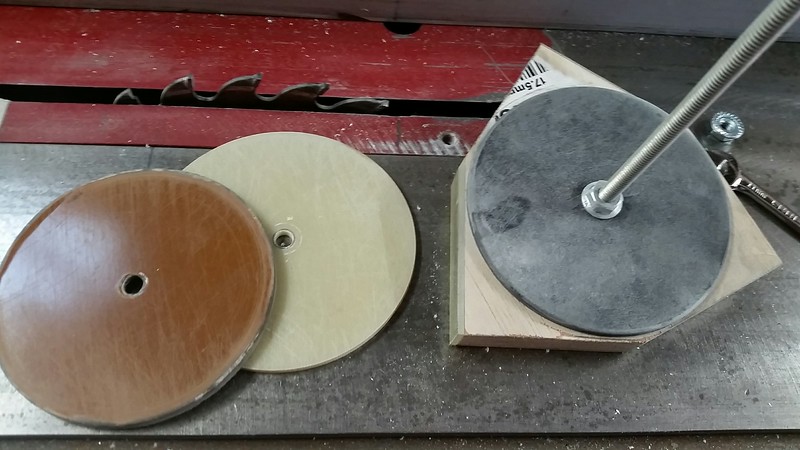
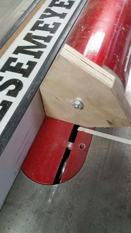
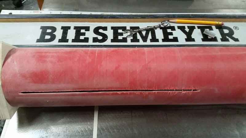
I'm a firm believer in that slotting for the fins on a min diameter rocket makes it stronger..
I came up with (or so I though I did) of a way to do nice slots on a table saw and made some cool pieces to assist in making the cuts straight.

44812203765_1fffa1f341_c.jpg


44812203865_98f8b0e724_c.jpg


44812203875_6b878e1860_c.jpg


The tube does loose it's roundness. So, I added a couple wraps of 2 mil mylar to a motor tube to get it back round to do my fin layups.
I still like doing "tip to tip" layups. I feel that the rocket poxy is a tad brittle and hard landings can make it come loose.

The fins were attached my normal way 1/3 - 2/3 - and almost full.. I use some chopped up are fiber tow and epoxy for the fillets, I do have some new epoxy that seems to work out well it's Loctite EA 9396 Aero It's a tad thick but I like it's properties and the price was right.

98a.jpg 98b.jpg 98d.jpg

You may notice that the coupler is pretty long. I wanted support all the way down to the top of the motor. The coupler is actually made from a spent AT 98mm DMS motor. I had to add 2.5 wraps of .75oz cloth to it to make it the perfect size. This also where my apogee recovery gear will be housed.
98i.jpg 9898j.jpg

More about the deployment charges later...

The rest of the electronics bay is straight forward..mostly
98e.jpg 98f.jpg 98g.jpg

The back side is just 2 tiered for tracker(s)..one weird thing is the top of the electronics bay is made out of some sort of test fixture. It's pretty cool material ..junkyard stuff.

And yes Chris. that is Basswood! Sandwiched between 1/32 G10...

Next, I'll talk about high altitude recovery and how and why those charges are mounted the way they are...

Tony
 
so at some point (altitude) you need to start thinking about "is this going to work that high up"? I'm often asked how highs is that? The answer has lots of variables to it. One is what and how are you currently doing your charges? In my opinion the worse charge holders are short and fat with the ematch on top. I'm not knocking you or anyone that uses them! They work! I've used them in the past. They just don't take advantage of all of the BP. Some of it gets scattered before burning. It sort of like the old short cannons...insert short fat cannon link here..https://silverhawkauthor.com/images...y-Museum--Goderich--Ontario--JustSomePics.jpg It worked..but in todays standards not very well. Now this is more like a real charge holder https://news.guns.com/wp-content/uploads/2013/07/iowa12.jpg

I'm also the guy that invented the latex tubing charge holder idea. It works..but some times, for whatever reason(s) it does not work. In the past I'd tell people it worked up to 104K. There's a new high altitude for it's use now.
latex 244K apogee 3.jpg


It says I've reached my limit...
more later..

Tony
 
to continue...
Below is some cut and paste from other threads I've posted to in regards to high altitude deployment........................................
March 2016 a good thread to read...https://www.rocketryforum.com/threads/high-altitude-recovery.133135/

A few weeks ago I got to playing around with various charge holders in my vacuum chamber. Jim is right Latex tubing does not fair well in "testing" situations. But it seems to do well in actual flights. I know it's worked up to 104K. I think the "trick" is, that the more jammed packed full your apogee bay is, the more likely the latex tube charges will workI did not plan on going into details here but briefly.... My test chamber is 6" dia and about 42" long with a 1" lexan top plate. I can draw it down to 27.5 mhg (photo). Inside this I place a my simulated rocket. FG tube 3.375 ID 24" long. One end has a removable cap the other end is open. Inside this I have a coupler that simulates the electronics bay. I use 3- 2/56 nylon shear pins to hold it in place. This coupler has fishing weights 76oz to give it some weight. (photo)The first test I did was with latex and a one gram charge. Only .4 grams was consumed and it moved the coupler moved 4"Jim's devices are very efficient consuming 100% of the BP. One thing that was very surprising was how energetic they are! In Jim's write up he states that they are VERY ENERGETIC. Which they are! I wanted to come up with something that still consumed 100% of the BP but was not as energetic. I started playing around with some 5/16" ID clear vinyl tubing. The finished item (photo) seems to accomplish what I was trying to do. 0.5 grams in my test chamber easily sheared the 3 shear pins, pushed the 76oz ebay complete through the simulated airframe and hit the top of my test chamber. This same set up (0.5 grams of BP) ground tested in my latest 3" min dia rocket sailed the nose cone and ebay 4 feet through the air into my moving blanket back stop without damaging anything. Normally I would have used 1.25 - 1.5 grams of BP to do this. Some notes and (more) rambling....The dog barf is only loosely packed to hold the BP in place and act as a shock absorber of sorts. The match is placed on top of the BP so that the BP is not blown out of the "charge holder" when the match fires. The BP has to pass by the other flaming stuff to exit the charge holder (100% consumed). The electrical tape is only there to hold the ematch and dog barf in place. It does not need to seal in or out in air. All test vacuumed soaked for 3 minutes prior to test.This has not been flown yet! Ground test before trying....Tony
______
Oct 2016 another good thread to read

I played around this past spring with a new take on Jim Jarvis's method. https://www.rocketryfiles.com/files/Technicalarticles/Jim_Jarvis_Highaltitude_deployment_2013.pdf Jim's device is VERY ENERGETIC. I agreed with his method but wanted to soften it reaction and still consume 100% of the BP. Below is what I came up with. I was only able to get my vacuum chamber down to 27.5 during the 5 min vacuum soak phase. I did not find it necessary to seal them. The black tape at the top of the charge is just to hold "things" in place.
Tony
_______________________________
lastly.....
Mark, Sorry for the confusion on your question. I place my ematch on top of the pile of BP. I'll give some history, then I'll state what I think is really happening (albeit non-scientific terms) I'm the guy that came up with the surgical tubing charges, Up to that point getting consistent deployment at high altitudes was iffy. The guys that seem to go well, at recovering from high altitudes seemed to a lot of BP. High altitudes (back 20) ago seemed to be flights of 20K or better. Yes, some colleges, Mark Clark, Frank and others had some really high flights. I did my L3 about 18 (?) years ago and went to 19,696 which at that time was a pretty high L3 cert flight. By the way I'm fortunate in that Black Rock is my "home field" For the longest time I just used charges in the tips of fingers from Latex gloves. I can't really recall what happened to make me look into a different confinement methods. I'm guessing the loss of a rocket or two! So my buddy Steve and I made up and 6" PVC vacuum chamber. I was testing things that I had seen on some of the college high altitudes shots. They were a lot like those big fire cracker things 80M (misspelled on purpose) As a professional Firefighter, I did not feel good about making or putting those sorts of things in my rockets. We did test some of them. They tended to scatter the BP all over the place along with all the parts of the charge "holder" too. We even tested an Estes B engine at a simulated 70K altitude. It lit fairly quickly but had way to much fire inside and outside the test chamber. Yep it ended up outside the test chamber on one test! I managed to extinguish the fire (yep we caught stuff not involved in the testing o fire. I guess now would be a good time for ...Kids, if you've read to this point please do not be like me! Don't play with fire!...So, at this point all of our test sucked. We had always heard that the reason for BP not working was that there was no 'air' for the BP to burn. Or it was to cold for the heat to transfer etc. I got to thinking. BP has it's own "air" and it's not 'up in the cold long enough to matter. It had to be a container issue. I used to race control line airplanes and we used to use surgical tubing for fuel bladders. We would use a syringe to fill the bladder with fuel and it was like the motors were on crack..sorry kids, just say no to drugs...So, I made up some BP charges using latex tubing. They worked really well. At the time I figured we had found a way to burn 100% of the BP at high altitudes. The highest altitude that I know of where the latex tubing charges were used was the 104K
  1. Over the years I would hear of a project or two where the latex charges did not work. Jim Jarvis had written up a paper on some of the tests he had done on BP at high altitudes. Jim found that they were not consuming 100% of the BP and that the % at times, was really not good at all. Jim came up with his copper pipe containment system that is pretty slick. So, a year or so ago I made up one of his systems and did some ground testing. In Jim write up https://www.rocketryfiles.com/files/Technicalarticles/Jim_Jarvis_Highaltitude_deployment_2013.pdf Around page 9 Jim makes a statement that his confinement system is VERY ENERGETIC. After my first ground test, which luckily was not in a rocket but out on the ground, there was no way one of my crappy rockets could withstand that! I put the stuff aside while I figured out what was going on and why.

    The following was, and still is what I think is going on when we use BP for ejection charges. BP has it's own "air". Our (at least my rockets) rockets don't spend enough time in the cold to have much of an affect on the BP converting into gas. The issue has to do with confinement and length of time that the BP is confined. I'm not using the word confined as in sealed. I'm using confined as in keeping the BP in close proximity to itself, each grain close to another. I'll talk about guns for a bit now. I know that guns with longer barrels shoot better then those with short barrels because the gun powder has more of a chance to be used up. So, a long skinny tube is better then short fat tubes for more complete consumption of the BP. Less will be scattered and not burned? Now where to put the match. Placing it at the bottom of the pile will start the process and start the burning pile towards the end of the barrel. Maybe some will not be actually burning by the time it reaches the end of the barrel? Now take that same pile of BP and put the match on top of the pile? The top catches fire and that gas heads for the exit while the piles is consumed it all has to pass the fire to escape out the open end of the tube? So why vinyl tube and dog barf. That's my attempt to make this type of ejection charge system not so violent but still use the "gun barrel" confinement method. I feel that the vinyl tube will expand some during the burn. The dog barf at the plugged end (hot glue plug) should help cushion the shock that way. The dog barf at the open end mainly holds the ematch and BP in place. The electrical tape just keeps things from spilling out. I found that it does not need to actually seal the air inside the tube.

    Also, this type of devise actually directs the gasses in a useful direction..and not just filling the body tube with gas.

    Always ground test...

    If I had to pick a number where to start thinking about high altitude issues it would be 23K MSL.

    That's my story and I'm sticking to it...

    Sorry for the gramer and spelling issues!

    Tony
_____________________________________________

Here's photo of what the above ejection holders look like.

vinyl tubing.jpg

Tony
 
Today I did some ground testing of just the charges for my new rocket...they are 5" long 5/16 vinyl. The tests were to see if my new plugging method would work and that the charge holders would work..more on these later..time for 4 short videos.
I need to mention...I live in a neighborhood were things that go bump in the day or night is not taken very well. The sound you hear is my leaf blower..masking the sound and smell!
1 gram


.75 grams


.5 grams


and..what happens if your recovery gears is in "it's" way.


and here is a photo of 1 gram burning with very little if any waste looks like.

1 gam burn.png

more tomorrow..

Tony
 
so mounting these types of ejection charges take some planning. They are directional and act as a 'ejection cannon'. You do not want any of your recovery gear in front of them. They need to be 'mounted' to a sturdy base too.

Below are some photos of how I mounted them to a beefed up electronics bay lid on a 3" rocket...
tube1.jpg
tube2.jpg

For this rocket I'm mounting them to the ends of the 1/4" all thread of the electronics bay. I ran the all thread long enough to add a 1/4" coupler nut. 3/4 of the length of the coupler nut has been turned down to 5/16" to fit inside the vinyl tube.

98k.jpg

98l.jpg

Tony
 
How I'm building the ejection charges...mostly photos.

The basic pieces. The vinyl tube come in coils. I like the pieces to be straight. I cut them to double the lengths I need and place a 1/4 rod/stick inside them. I then place this on the dash in my truck. They heat and and become straight. For these I'm using "plugs" instead of a Hot Glue plug. There is/was nothing wrong with the hot glue plugs I'm just trying something different. These plugs are made from a 3/8" silicone o-ring. They are about 1/2" long and slightly tapered on one end. I've fired about 9 of these with the silicone plugs..with no issues. I'm going to try using some super glue on these. They were a bitch to get set in the right place and I think I'm going back to no super glue one them..
vt8.jpg


The aluminum thing with the 1/4" and 5/16" bolts helps me get the plug where it needs to be and a gauge to let me know it's in far enough. The green thing is a funnel and the allen wrench is being used as a packing tool. When I say packing..I only mean for the dog barf and it's just lightly packed.
vt7.jpg
vt6.jpg
vt5.jpg
vt4.jpg

Key point..the ematch is on top of the BP!!!
vt3.jpg

Another plug of dog barf to hold the ematch in place..
vt2.jpg

Finish it off with electrical tape holding the ematch in place..
VT1.jpg

Tony
 
My apogee bay is 3.625" dia and 5.75" long 60 cubic inches. There are three 2/56 nylon shear pins

.5 gram test.


3/4 gram


1 gram


Tony
 
Hi Tony,

Thanks for sharing this thread, it's quite insightful. I've been going down the path of determining how best to do high altitude apogee deployments as well. That said I've decided to use "charge cannons" similar to what Mike Passaretti and Nic Lottering have used in the past for their high altitude flights. Here's a shot of three of these units; the two smaller ones are for 54mm MD rockets whereas the larger is for 75mm MD rockets.

LJMzt0RA6Q9q2RCAp9U5RLpe4gw2SQvXZAa7g0Dc1Xo-UskZ3_tc8nDkwT39liBE-Q-Z2cQIsF9YGfvlYu9Sec45RQp0B3PUlRPYDuAOyM8efzGnim1JX5m4CW18E5sHghli_8fuHYK-x3riEdKDPJFi1HqYqup1BpEs34jaJKvYLKTymLh1Mbv1EhLrsEoblZHNV0fBn7_nQYRMqkdfFJ0Mbov5nLo0Fhf1JTz6zZmPLHi4ygljCgt2eZlCQb2keDxvJ2pMt2c1J8RxFFHkJaSBchrA45Z1JEWXWiIqLs9nwQzfLSwolj9l-8gCP_eANyLs6bY_NRqjudZZ8WMnUV3hfJhlG4sQs1mUWTklEVcxVVCeMDviafSC_kAoABeYcn5_bwYt92GTIEqwQEDSvpVL-eFqj4xLBP2TJYtejcIGBipw2TkV7BLR20j3mA53uZeg4Hwt2_yJnONqKOxqkDKRM41YWK9EFqs1Lh-TQq1FNQZA7t5qlpvoieY1WpagKHF-_kOQUMYhc9PRbZDiq8_yPoDMnKQPf6vxGIMvKU8WB7yoi3wH6xpA7kbCSKTdqE3JN-1_U6ew_bMOtdG40MoY4PUWameDUeWZ_H17a5pwTk7ROZBlAojIsnJDiRKCOupTQnh5WdB2X06t-Oa3rDVjFBLxWLvObbqDTnzudMgJB1zc3RTjNGP8VZJ3Bt0T0EVR2Ldxk00WZHswEtO1r9QHJw=w721-h961-no

As you can see unlike Nic and Mike I've not chosen to make my cannons nearly as long as they did. This decision was made from a functional perspective more than anything else as I wanted to incorporate them in a single break HED design that frees up the aft part of the AV Bay to also serve as a threaded positive retention motor mount.

Here's a shot of the 54mm AV bay with the charge cannon mounted nearly flush to the bulkhead.

5IWHcu7LuMccw6Rkp71iB3iAi2QgcT9OQeQ_iAom28U1ZXSku4FIgWtZbgfWcEJ0_NWCbAxcDzkDA7tvYiHK8IqEISdNICdHXSSBJF4tfD7qmzKc11-_4fOpHfjPTYSqB99oQnfte7hghWK7EW1f_VUPPRZ0uVd5ikxHyhLZ9guskk6MYsNLrNdrodc9wDSCzAPIgV954ie3vTE6bYj5R1awsQVs5NJ2ocTokDPRgFpYLx5gmOzxXT9a3oSC8R7e0yjzyUHjBZ6HOAdrJhs-e7jFaeRIeU4WWCJ5CkXsPIZIHYX_MQD7ZnrnTE1hCcABhHcMVtMmBgYZNtQ15B8QzVZDtM-6DPVZXSAI3AA5FiyoOe5l3mHvT-OICf1JePHx3qA6_1yz-5NHFPt2tyonn_wKVkPTMYk15zDp2ey1Du-mZssvH4sjRffaeogCcmmUtPWKgNjYTLbAbAJVcWxH_lBwiDJsSu-IsQiw_MxYsVPu2MrzsbM85wB2OQm9NfUC6K1IVLcDOn0psQ4qKupKgBXm_xyu3AM427acoRVUTowAaf8MPUverZDIHUAmFU5xDBQcwoEvFsh9viGnC9lnw4g-9C4YOvdz5K-e-lodTDUdCw4WEyw2YtR6i1BH28ZgxETQvnI4uVOE9WspEEF9GfddSleNUeDkH3P0zyqFRE3S8nASIdWxDMQma7yLewW7ZpvmUK7OX9QrQnjfUsAff1heIw=w721-h961-no


And here's a largely unfinished shot of the 75mm unit.

2p4BCXAEPz0TkMwAHHCQhSJEgyJgHtyA4DpPuZ3-WJ9v7yfh2MWDKfSn0RRcXWxZFU96wSXOh4qSZVAiwdJNDPsIRL1ETk1QmiulIexTU0chUSMW-NHUCzuByHMhYNYVaUXIGwdNcgVNwdevcaGtXgDRuenIDRBMk2u-rnhK_4UU50v5lppvJBoBggrr1X7hrH_n77t6zuMxife5AF0SWS61bVmd0oDKgHMVnZsBh0Mo3Lantt-eILuzla2cAvhPibpflxb7oOm6jHvhJj0IYn5h2rAPsKSuiQ7uGfML60Y8YEyyVRuNCaBMxfRXJr4XSvaLUNLRMjbaKexCi42nXrjzq_1uMgiWI7vmWQPq7aYtxdajlYgQyGlyy1c7Xd-01af4RoLOnSyC-B8VDdbtedZol9dojiw6awDGRywvqpq3LwnA_JgoQElX3HnD7orQ886MOFqdBAitLmGloxWQyU1rGw_bBOo1K7Y6_IJzT6i27PaLLL8DyMcoqLUdRE_QD36mD5qdG_57Ga1T6W4CjleD3FVWA95mSvtcuxYOIJDXOegBP7pxUv7MrPrwEFK-QdIh93deTJ5ldzRfM3H9a6QFTqaenuLxyh0muYsurGPVjHpmrpnTlu9_ddPBj09CG-qP9VUvegCcvhQXw7dG3z9iZ5kCmZw3rcEvU2YwZsEJKNx5Oa1M8yK51FiJcLngA91T8GyrIQigDO_zA9cZOd4NIQ=w721-h961-no


I took two rockets to THUNDA down here incorporating this design. The 54mm unit worked as expected and recovery was nominal. Apogee was just short of 27k'. The 75mm rocket lost a fin at around Mach 2.9; that charge cannon didn't fire as my Raven lost power shortly after everything went pear shaped.

Whilst at THUNDA I had a chat with a fellow high altitude/MD junkie and showed him my cannons (no pun intended). He's (independently) been going down a similar path as well. He's spoken to a number of muzzle loading enthusiasts and according to them you ideally want a 10:1 length to ID ratio for these sorts of devices if you want to ensure full BP combustion. Think of it from a rifle perspective; all things considered a short barrel will result in a bullet leaving the barrel slightly slower when compared to a longer barrel that allows full combustion of the BP. The 10:1 ratio was apparently arrived at in the 19th century in artillery circles as the minimum ratio required to ensure full powder combustion.

My loading process is BP in the bottom, then E-match on top. Finally I fill the rest of the cannon with dog barf before taping up the top with electrical tape. Credit to CJ, if it weren't for his thread comments on placing the e-match ON TOP of the BP instead of at the base of the charge cannon I'd most likely have done it in the less optimal way.

Once again, thanks for sharing.

drew
 
The design is what I call an "AeroPac Sport flyer" I'm not trying to be funny or slam other people. I'm lucky in that Black Rock is my home field. With that being said I've seen a lot of record altitude attempts. Mostly just attempts. The two biggest issues are construction not up to the task or poor design. Most of the stuff I've learned has been at other peoples expense. And lots of my own thrown in for good measure.
I'll start with design. Some attempts go unstable fairly quickly. I call these rockets glass slippers. If everything is just right they work and get some amazing altitudes. When they don't work they disintegrate. These rockets usually have one or both of the following issues. The fins only have 1 caliber of span and the rockets stability margin is 1 caliber or slightly more.
I like my AeroPac Sport flyers to have fin spans of 1.1 calibers. This seems enough to keep some fin in clean enough air to over come any mishaps.

lol @ glass slippers. I remember those days fondly; guys would show up to Balls with N5800 designs and simulation backed declarations of getting near 100k' with their rockets. Most didn't crack 1k' but were exceptionally fun launches to watch.

I remember when Mike Passaretti finally successfully flew the N5800 in a MD bird at Balls 22. There was a slow but steady procession of flyers to the Australia camp looking to see the rocket that was finally able to tame the beast. Most had tried unsuccessfully before. Most of their rockets were either a) inherently unstable for the duration of the N5800 burn (aka team lunar coning) or b) weren't built strongly enough to hold together for the boost.
 
With your buried charge canisters consider adding an o-ring grove to the top of them. Taping over the top can be a bit unreliable (read very unreliable). Tape over the top and clip it in with an o-ring is nice and confidence inspiring. Personally I use a high-temperature Kapton tape.
AssembledAvionics.JPG

If you have the charge otherwise constrained and then in the well, ignore my ramblings...
 
Question for Tony, you mentioned caution to be sure that the recovery gear is not directly in front of your charges going off. What do you do to manage/keep it safe?
 
With your buried charge canisters consider adding an o-ring grove to the top of them. Taping over the top can be a bit unreliable (read very unreliable).
I think that might be more important if I was using charge canisters that were facing the ground during boost. I'm not doing that. I'm only using these charge cannons for MD birds and the cannon is facing skyward during boost. I suspect I'll be ok given that design difference.
 
Plugger, Thanks for adding info to this thread! In one of my posts above I made reference to "I came up with (or so I though I did)" comment. Now you show me some fancy metal ejection cannons...from down under. (seems like good/great ideas, concepts and techniques take time to travel up and around to this side of the planet.

So can I say I came up with the idea for DCC's (Disposable Charge Cannons) [ala Aerotech DMS motors] atleast?

Yep..those N5800's ate a bunch of rockets!

Tony
 
FWIW. The skinny Doghouse Rocketry charge holders work well with the red AT ejection charge plugs that come with the BP kits for the AT electronic ejection timer, providing an airtight seal. I feed the e-match through a hole at the bottom and cover hole with epoxy. The rubbery toughness of the AT plugs extends the containment time. That's my theory anyway. I've used this setup up to 40k, and see no reason they wouldn't work higher.Not much difference b/w 40k, 60k, 80k or higher from a practical sense. The O2 goes from extremely low to non-existent.
 

Attachments

  • Doughouse.jpg
    Doughouse.jpg
    69.5 KB · Views: 100
  • Doghouse.jpg
    Doghouse.jpg
    60.9 KB · Views: 90
Last edited:
Question for Tony, you mentioned caution to be sure that the recovery gear is not directly in front of your charges going off. What do you do to manage/keep it safe?

Good question Allen..

The way I have them mounted (to the ends of my ebay althread) does a few things for me. Gives them a strong base, keeps them pointed in the right direction. Keeps them off to the side of the compartment and are long enough to pack all of my recovery gear above the business ends of the charges. The "well" in the top of the 98mm FC is what they are firing into.

Tony
 
Plugger, did you turn your cannons on a lathe yourself, or is that something you bought as-is? I really like the recessed cannon concept to save space.

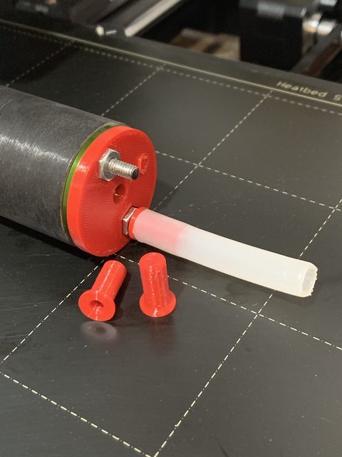
I'm working on a concept similar to tfish's, but for 38mm min diameter (not enough room for a recessed cannon here). The charge tube is 1/4" polyethylene tubing (refrigerator water line) with 3D printed plugs that fit very snugly in the tubing, and are easily threaded onto the 8-32 avbay rods to serve as a stand-off. The BP and match will be in the middle with wadding, and probably another 3D printed plug on top with a notch for the match wires.

The stand-off plugs are half hollow, half solid so that if it did happen to break during handling, the solid part will stay in the tube. The top plug will likely be all solid and fit a little less snugly to make sure separation is in the direction I want it to be. This is all in prototype phase and has not been tested with a charge yet.

The 3D printed end plate is not structural and may not get used at all; it was intended to have the integrated stand-off to stick the charge tube on, but you can see the scar where it broke off at the 3:00 position. Turns out the threaded rods make a much better standoff. The plate is just serving as a lock for the nuts which are recessed into the plate. Wingnuts will go on the other end for normal servicing.

5KvjhlFl.jpg
 
Back
Top