3D Printing What 3D printing program is best for making rocket parts?

The Rocketry Forum

Help Support The Rocketry Forum:

This site may earn a commission from merchant affiliate links, including eBay, Amazon, and others.
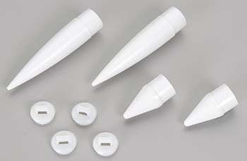
So here are the legth dimensions for an aphla nose cone , 2.75 in make the adjustment.. tinker cad isnt helping how do i down size from the large to the smaller work plane to make the nose cone exactly?
 
Matt, I'm not sure I / we follow what you're asking.

Are you asking about attaching the NC to the rocket in the real world? (this you should now, via a shock cord!)
Are you asking how to assemble the parts in CAD (In CAD, you need to make an assembly file, and constrain the parts to each other)

As for your 2nd question, you should be scaling the part. There should be a function to 'scale' the part, and its in percentage.. a 50% scale would reduce the model to half it's size. a 200% scale would increase it to 2 times it's size. Do you know how to work out what your scale factor (the percentage) should be?
Ok i got the scale part down ty , I was mentioning the actual nose cone to a model rocket , via the little arch that allows you to attach para and shock ... (this can be done but its proven to be to brittle)
 
Ok i got the scale part down ty , I was mentioning the actual nose cone to a model rocket , via the little arch that allows you to attach para and shock ... (this can be done but its proven to be to brittle)

Are you printing in PLA? Do you have access to PETG, or can the printer handle ABS?

By the way:
IMG_0987.jpg
 
OK, so what you are asking is that the attatchment is too weak, and you want o improve it; make it thicker / stronger / more resilient to shock loading. You want to make what you show in post #49 look like the parts in post #60.

Something like this?

nc-matt.jpg

Again, why not make a boss and use an eye screw? much easier to model a hole than an eye in the part. Easier to print, and will be stronger too..
 
OK, so what you are asking is that the attatchment is too weak, and you want o improve it; make it thicker / stronger / more resilient to shock loading. You want to make what you show in post #49 look like the parts in post #60.

Something like this?

View attachment 381598

Again, why not make a boss and use an eye screw? much easier to model a hole than an eye in the part. Easier to print, and will be stronger too..
yes exactly that but ... i still think that the way its going to print its going to have the most amount of stress, i think the viking version i showed you printed separate is going to be just fine, or if you want to make the print a bit more buff you could print the two pieces as a whole. ( I'm saying this due the fact that in Physics wise that plastic is must more out there and would cause stress points via cracking so yeah)
 
OK, so what you are asking is that the attatchment is too weak, and you want o improve it; make it thicker / stronger / more resilient to shock loading. You want to make what you show in post #49 look like the parts in post #60.

Something like this?

View attachment 381598

Again, why not make a boss and use an eye screw? much easier to model a hole than an eye in the part. Easier to print, and will be stronger too..
actually im regarding Mid to low power rocket build not high powered part.. just and fyi
 
Matt, the plastic is strong enough. It's the layering that makes it weak. Design and engineering is all about compromises. Why try to re-create a aprt that works for one method of manufacture to be equal for another method. Design it to solve your problem, and for eh method of it's intended manufacture.

As I mentioned in a previous post, a boss with a steel #4 or #6 eye screw will be plenty strong for your application, for a NC up to a few inches in diameter. it's easier to print, and doesn't have the weak point that you're trying to solve. (Some HPR NCs with added with weight rely on a threaded eye bolt in a boss).

No one says you need to print it straight up! But it is the easiest way. If you were to lay the NC on its side, with the loop part parallel to the print bed, that would ensure the layers are perpendicular to the intended loading of the part. But, that' somewhat impractical because pretty much the whole NC will need supports when printing: time consuming, a waste of plastic, and a pretty rough surface were the supports were.

You also have to think about how the initial two parts you're trying to emulate are made: the first one is a blow-molded part. The 2nd (Viking) is a molded part (2 parts actually). You need to understand that each process has it's own advantages & limitations, and those are somewhat overcome with 3D printing. But a 3D printed part has it's own set of limitations (the layering & layer orientation for one).

https://www.sinotech.com/resources/tutorials/blow-rotational-molding/

https://www.custompartnet.com/wu/InjectionMolding
 
again i like the concept idea but how do you attach it to the rocket without it breaking , this nosecone isnt the problem it the attachment part which you add a shock cord too. Actually i sorta have an idea on that one , you know the viking rocket nose cone?

est303161.jpg


That probably can be made exactly like this just larger , maybe a thicker cone size also

Glue a foot long (or twice the length of the nose cone) piece of kevlar line along the inside of the nose cone up to the tip along the side. Thread the line thru a hole in the base before you attach it. Use 750# test for rockets under 3" Larger as needed for bigger diameters. 3D printed nose cones will have a rough finish so epoxy will stick great.
 
Well its been said and said again but if you start counting votes I figure I had to get mine in for Fusion 360. Can't speak highly enough about it, although in reality whatever you get fluent in and learn well (assuming a reasonably capable software) could do you well. I have Creo, Solidworks.....but I now like Fusion the best. Great value and as its also been stated - free for hobbyists.......
 
Well its been said and said again but if you start counting votes I figure I had to get mine in for Fusion 360. Can't speak highly enough about it, although in reality whatever you get fluent in and learn well (assuming a reasonably capable software) could do you well. I have Creo, Solidworks.....but I now like Fusion the best. Great value and as its also been stated - free for hobbyists.......
can you tell me how to get that?
 
can you tell me how to get that?

See post #35.

Another vote for Fusion 360, but once you understand parametric CAD design, Fusion 360, SolidWorks and OnShape (also free BTW) all operate similarly. Between work and home I use all three, but I like that Fusion 360 has pretty powerful CAM built in.

Randy
 
I can't stress that enough, they all work pretty much the same. if you don't know (or can't grasp) the basics of modelling, they just get harder & more frustrating.
 
Back
Top