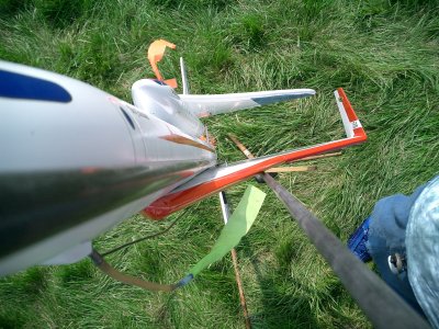
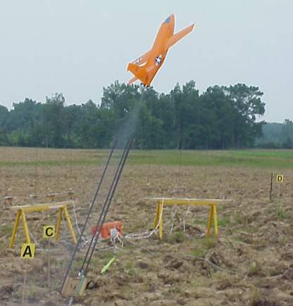
I used water ballast in the nose of my R/C X-1, because of the lost mass of the propellant of the G12 reload in the tail. The model had to have an exact glide CG, could not afford to be tail-heavy at liftoff, and could not be nose-heavy for glide.
https://georgesrockets.com/GRP/Scale/X1.htm
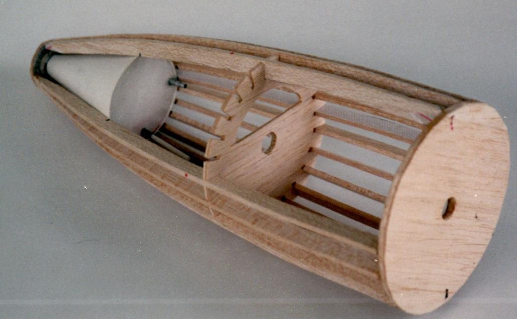
I came up with a system that let the water begin to drain as it lifted off (literally unplugged a plug), and the drain rate slightly longer than the burn time, I think 10-12 seconds to drain (in ground testing), the burn time was 8 seconds. I figured acceleration would increase the drain rate a bit, but still would not drain empty till after burnout. But it was easy to drain the rest., because the model was a glider and the dump port was plumbed to exit out underneath the nose. In the photo below, the X-1 nose section being built, with the water tank installed (white plastic conical tank, a custom vac-form I made from an old Shuttle SRB nose cone mold). The dump port is seen near the bottom, among the lower balsa stringers. The other port seen to the right of the tank base was the vent port (it had flexible silicone tubing added to it, to allow excess water to vent out thru the lower part of the nose when water was being forced in by the dump port. I used a rubber squeeze bulb (for model plane refueling use) to force the water in.
To force water out of a regular rocket, one way would be to use a long skinny balloon, and use its pressure to squeeze the water out. But finding the right balloon to match the rocket diameter could be an issue. Also, if the balloon bursts, water damage among other issues.
Let me ask the big question: WHY? There must be a reason why you want the stability margin to change in flight. Hmm, in rereading, maybe you did not mean during flight?
There could also be a mechanical method. Such as a screw-drive system with a very long threaded rod causing a mass to move lengthwise inside the model to shift the CG.
Also aerodynamic methods, but those mess with the external appearance and get trickier to do.


")