An "R"-powered rocket build

The Rocketry Forum

Help Support The Rocketry Forum:

This site may earn a commission from merchant affiliate links, including eBay, Amazon, and others.
Status
Not open for further replies.
I like this modular design as well. especially as you will have every opportunity to execute some solid composite work and cure each piece individually and under optimal conditions.

also, and I may be wrong here, but each section will in fact be a bond between a pair of 3/4" CRs correct? from the aft it would be: thrust plate - 'CR, coupler, CR' - 'CR, coupler, CR' - 'CR, coupler, CR' etc. with each 'group' being its own fully bonded sub assembly. correct?

the only real challenge I foresee is actually inserting and properly bonding each section into the airframe as there will be substantial friction imposed by the epoxy on each coupler section. I am sure that we have all had aspirations of sliding a coupler in an airframe for added strength only to find that it "wouldn't go" any further. its a pisser on a 3" rocket but a killer when dealing with the materials and overall time & effort of your project.

again, really dig the modular design


Yes the sequence you described is exactly how it works.

Good point about fitting them in. I've got the 80-grit aluminum-oxide belt sander ready lol. When it comes time to fit I want to do it all in the 90 minutes working time.

Chuck C.
 
I don't think I grasped what you mean by "each section will be fiberglassed before installing in the rocket"

Are you referring to fiberglassing the interior of each coupler unit?
 
I like this modular design as well. especially as you will have every opportunity to execute some solid composite work and cure each piece individually and under optimal conditions.

also, and I may be wrong here, but each section will in fact be a bond between a pair of 3/4" CRs correct? from the aft it would be: thrust plate - 'CR, coupler, CR' - 'CR, coupler, CR' - 'CR, coupler, CR' etc. with each 'group' being its own fully bonded sub assembly. correct?

the only real challenge I foresee is actually inserting and properly bonding each section into the airframe as there will be substantial friction imposed by the epoxy on each coupler section. I am sure that we have all had aspirations of sliding a coupler in an airframe for added strength only to find that it "wouldn't go" any further. its a pisser on a 3" rocket but a killer when dealing with the materials and overall time & effort of your project.

again, really dig the modular design

In my experience, the only time I've gotten something stuck was with Titebond on cardboard tubes. Epoxy seems to lube up the parts, at least until it sets. As long as everything fits dry, it should fit wet. You probably have this down already, but it would be a good idea to number the parts so you put them in wet in the same order that you did during dry fit.
 
In my experience, the only time I've gotten something stuck was with Titebond on cardboard tubes. Epoxy seems to lube up the parts, at least until it sets. As long as everything fits dry, it should fit wet. You probably have this down already, but it would be a good idea to number the parts so you put them in wet in the same order that you did during dry fit.

That’s exactly why I prefer epoxy over Titebond.
 
In my experience, the only time I've gotten something stuck was with Titebond on cardboard tubes. Epoxy seems to lube up the parts, at least until it sets. As long as everything fits dry, it should fit wet. You probably have this down already, but it would be a good idea to number the parts so you put them in wet in the same order that you did during dry fit.


Not a bad idea numbering them lol.

I like Pro-Set super-tough epoxy. It doesn't run at all and is one of the strongest epoxies out there. And yes it does allow the coupler assemblies to slide in although Theory is right in his caution.

Like you said if they dry-fit well that should do the trick.

Chuck C.
 
the only real challenge I foresee is actually inserting and properly bonding each section into the airframe as there will be substantial friction imposed by the epoxy on each coupler section. I am sure that we have all had aspirations of sliding a coupler in an airframe for added strength only to find that it "wouldn't go" any further. its a pisser on a 3" rocket but a killer when dealing with the materials and overall time & effort of your project.

Theory,

THANK YOU for bringing this up !

That is a VERY valid concern . . . The greatly increased surface area involved would certainly magnify the forces involved.

I strongly advise Chuck to thoroughly test his installation methods on additional or scrap components, before committing their use to the actual airframe !

Once you start, you are "committed" and speed is very necessary to minimize the "grab factor" ( my term ) . . . The use of shorter coupler sections makes this easier than using long segments, but the risk is certainly there.

I have certainly experienced using couplers to "double" smaller rockets, some with great success and some resulting in a trip to the trash can. On small rockets, this is an annoyance and an inconvenience. On a project of this magnitude, it could be devastating !

Dave F.


pirate-talk-clipart-1.gif
 
Not a bad idea numbering them lol.

I like Pro-Set super-tough epoxy. It doesn't run at all and is one of the strongest epoxies out there. And yes it does allow the coupler assemblies to slide in although Theory is right in his caution.

Like you said if they dry-fit well that should do the trick.

Chuck C.

Hi, Chuck,

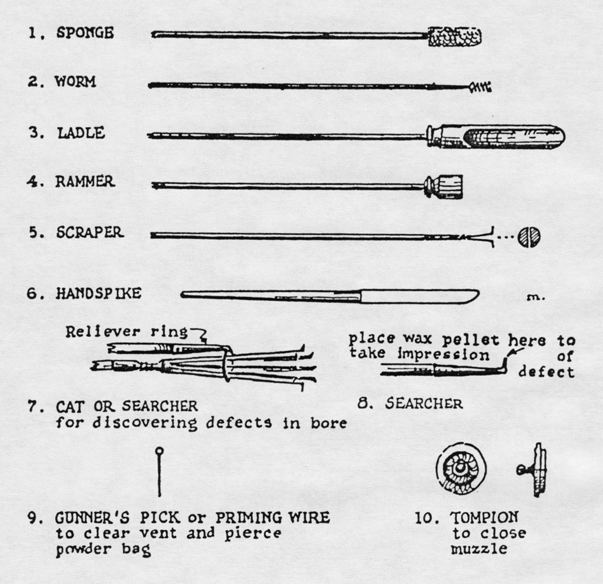
Perhaps you could devise a "rammer" of some type, to aid is getting the couplers & rings down the "bore" of the airframe ?

Dave F.

The-Constitution-Gun-Deck-12a.jpg


pirate-talk-clipart-1.gif
 
Got a question for you rocket-types.

When building the modular couplers I'm also going to place carbon-fiber (I switched from glass because I found a great price on carbon from Public Missiles) over all the CR's in a length-wise fashion.

This is to bond the CR's completely to the ID of the coupler and the 3/4" birch stringers.

If I slide the coupler assemblies in one at a time I can ensure there is a good epoxy bond between the airframe and each coupler. However if I do one at a time I have to reach into the 5' tube to CF the CR's after they are touching.

Also one at a time will create an epoxy fillet on the upper CR as it slides in creating a gap between modules.

I can build all 4 24" coupler sections as one unit enabling me to CF all the CR's rather easily. However when it comes time to slide the entire unit into the airframe there won't be as much epoxy between the airframe and couplers.

So all you rocket scientists get together and tell me something I'm missing.

Thanks!

Chuck C.
 
Curious here, and more thinking out loud than anything, but what is the thickness of you G12 airframe? If it’s substantial, howbout screwing the CRs? Solid steel screws and that top notch epoxy should do the trick.

I do have to say that the friction load of sliding 5’ of coupler/CR into an airframe with everything slathered in epoxy could be VERY substantial.
 
Last edited:
When building the modular couplers I'm also going to place carbon-fiber (I switched from glass because I found a great price on carbon from Public Missiles) over all the CR's in a length-wise fashion.

This is to bond the CR's completely to the ID of the coupler and the 3/4" birch stringers.

Still having trouble visualizing this. Maybe a drawing or sketch would clear things up?
 
Still having trouble visualizing this. Maybe a drawing or sketch would clear things up?

There will be strips of CF running vertically over the ID of the CR’s.

There will be enough room to do this and have the motor fit.

We’re really only concerned about the motor having tighter CR’s at the very bottom and top of the casing.

The rest of the CR’s are for internal strength using birch stringers. We want all of that structure CF’ed good and strong.

Chuck C.
 
Curious here, and more thinking out loud than anything, but what is the thickness of you G12 airframe? If it’s substantial, howbout screwing the CRs? Solid steel screws and that top notch epoxy should do the trick.

I do have to say that the friction load of sliding 5’ of coupler/CR into an airframe with everything slathered in epoxy could be VERY substantial.

That may not be a bad idea.

I think the CF’ing of the CR’s is to ensure the stringers have a rock-solid base on which to transfer the motor thrust from the thrust ring into the entire rocket.

It might be overkill but I’d like to error on the too much side.

Chuck C.
 
I hear yea. Just thinking that the screws will make up for lest than optimal epoxy coverage that may result from sliding the entire assembly in at one time
 
Maybe the solution is to not add the CF on the inside of the CRs until after everything is glued up? I'm thinking that if you laid up some full length CF staves (maybe 6 or 8, sort of like this bearing: https://www.duramaxmarine.com/advanced-stave.htm), you could slather them with epoxy and then drop them into the tube after you have the coupler sections all in but before the epoxy is fully set? You'd make the staves and clean them up so they're nice and straight well before the assembly job and dry fit them along with everything else. You'd have to be careful not to get stray epoxy on the CRs where the motor casing fits tight and you'd have to figure out how to hold them all in place. For the latter, you might use a fan + plastic sleeve setup like they use for ventilating enclosed spaces on job sites. The pictures I'm seeing on Google are all of re-usable hoses, but I usually see them with disposable plastic hoses, about the same thickness as plastic dropcloth.

That option gets you a continuous support that you can add after the stressful job of getting all of the coupler pieces in place. With a good slather of epoxy between the staves and the CRs, they wouldn't have to be a perfect fit (epoxy likes to fill small gaps) and they wouldn't necessarily have to even touch the adjoining stave.
 
There will be strips of CF running vertically over the ID of the CR’s.

There will be enough room to do this and have the motor fit.

We’re really only concerned about the motor having tighter CR’s at the very bottom and top of the casing.

The rest of the CR’s are for internal strength using birch stringers. We want all of that structure CF’ed good and strong.

Chuck C.

Chuck,

I feel that "vent holes" in the Centering Rings are a good idea. There will be a large, rapid drop in air pressure as the rocket ascends. That, coupled with aerodynamic heating and thermal energy released from the hot motor, might place too much stress on the assembly. Allowing the pressure to "equalize" should alleviate this situation.

Dave F.


pirate-talk-clipart-1.gif
 
Last edited:
Chuck,

I feel that "vent holes" in the Centering Rings are a good idea. There will be a large, rapid drop in air pressure as the rocket ascends. That, coupled with aerodynamic heating and thermal energy released from the hot motor, might place too much stress on the assembly. Allowing the pressure to "equalize" should alleviate this situation.]

X2 for all of the reasons given!
 
I hear yea. Just thinking that the screws will make up for lest than optimal epoxy coverage that may result from sliding the entire assembly in at one time

I hear what you're saying. One problem with sliding in one section at a time is there will be an epoxy fillet formed at the CR where it picks up epoxy as it slides in.

I'm not sure if having even a 1/4" gap caused by these fillets between CR's is a good idea. The intent is to have (8) birch stringers in each coupler section that in effect are continuous from the bottom aluminum thrust ring all the way to the upper thrust ring 9 1/2 ft up.

Not saying it's a problem... just something that has to be addressed. For either method of insertion there are pros and cons.

But I really like this modular concept and I'm excited to begin the contruction.

When we start the "S" rocket project with 16" G-12 this method will transfer right over. I've always really enjoyed working with G-12 as an airframe as it's tough and when I take it to the body shop for paint it's a smooth surface that takes paint well.

Please keep the ideas and suggestions coming. They are very helpful and keep me thinking.

Chuck C.
 
Had dinner with my folks this evening and was discussing this rocket.

My dad mentioned the reason I got out of rocketry back in 2005 was because I had kind of reached the pinnacle of motor power. Granted it was a 2-stage "O" rocket and there was a couple of "P's" and even a "Q" being flown but that was it.

It's amazing we can even discuss "R" rockets and probably even an "S".

My dad laughs because he retired from Aerojet 20 years ago and he said the motors we're flying now are about the same size Aerojet was making for the military missiles.

We sure have come a long way haven't we? Never thought in a million years we'd be discussing projects of this size. Got to hand it to Tripoli's EX program and their willingness to allow us to push the upper limits.

Just thought I'd share lol.

Chuck C.
 
Chuck,

I feel that "vent holes" in the Centering Rings are a good idea. There will be a large, rapid drop in air pressure as the rocket ascends. That, coupled with aerodynamic heating and thermal energy released from the hot motor, might place too much stress on the assembly. Allowing the pressure to "equalize" should alleviate this situation.

Dave F.

Yep that makes sense Dave.

Thanks.

Chuck C.
 
Maybe the solution is to not add the CF on the inside of the CRs until after everything is glued up? I'm thinking that if you laid up some full length CF staves (maybe 6 or 8, sort of like this bearing: https://www.duramaxmarine.com/advanced-stave.htm), you could slather them with epoxy and then drop them into the tube after you have the coupler sections all in but before the epoxy is fully set? You'd make the staves and clean them up so they're nice and straight well before the assembly job and dry fit them along with everything else. You'd have to be careful not to get stray epoxy on the CRs where the motor casing fits tight and you'd have to figure out how to hold them all in place. For the latter, you might use a fan + plastic sleeve setup like they use for ventilating enclosed spaces on job sites. The pictures I'm seeing on Google are all of re-usable hoses, but I usually see them with disposable plastic hoses, about the same thickness as plastic dropcloth.

That option gets you a continuous support that you can add after the stressful job of getting all of the coupler pieces in place. With a good slather of epoxy between the staves and the CRs, they wouldn't have to be a perfect fit (epoxy likes to fill small gaps) and they wouldn't necessarily have to even touch the adjoining stave.

Boatgeek thanks for posting that link. Looking at those staves does get one thinking.

It's going to be nice when Curtis Turner gets the tubes and couplers finished and sent to me. Will finally be able to put the design ideas into action.

Chuck C.
 
Had dinner with my folks this evening and was discussing this rocket.

My dad mentioned the reason I got out of rocketry back in 2005 was because I had kind of reached the pinnacle of motor power. Granted it was a 2-stage "O" rocket and there was a couple of "P's" and even a "Q" being flown but that was it.

It's amazing we can even discuss "R" rockets and probably even an "S".

My dad laughs because he retired from Aerojet 20 years ago and he said the motors we're flying now are about the same size Aerojet was making for the military missiles.

We sure have come a long way haven't we? Never thought in a million years we'd be discussing projects of this size. Got to hand it to Tripoli's EX program and their willingness to allow us to push the upper limits.

Just thought I'd share lol.

Chuck C.

Chuck,

So, is your Dad "on board" now ?

If so, he will need "suitable attire" . . .

Dave F.


578f1555e798ad9601d094adf10e4194--pirate-fashion-crossbones.jpg


pirate-talk-clipart-1.gif
 
I hear what you're saying. One problem with sliding in one section at a time is there will be an epoxy fillet formed at the CR where it picks up epoxy as it slides in.

I'm not sure if having even a 1/4" gap caused by these fillets between CR's is a good idea. The intent is to have (8) birch stringers in each coupler section that in effect are continuous from the bottom aluminum thrust ring all the way to the upper thrust ring 9 1/2 ft up.


When we start the "S" rocket project with 16" G-12 this method will transfer right over.


very true that epoxy will be picked up and pushed forward as the assembly is slid into position. the amount of which can be easily control by how much is applied and where it is applied. also, rotating the assembly will serve to distribute some of this as would substantial pressure that would "squish" the adhesive laterally. doing this in consistent manner will be tricky, but could be done. I agree that 1/4 inch between CRs would not be good, but a 1/8" epoxy joint shouldn't be an issue, however something that must be accounted for in the final build, as an 1/8th here and 1/8th there adds up to a very real dimensional change.

as for any future projects, I would strongly suggest pumping the breaks on those. you are implying that this untested and yet to be constructed design for which all parts are not even acquired, will be used again to support a project that is twice as powerful. likely not the best way to do things as every rocket build is a learning experience and a time to continue to hone ones skills.

slow, steady, test, retest and you will be good to go!
 
Hum ... would one of these aid in the "squish" factor as the build progresses?

https://www.baileigh.com/hydraulic-shop-press-hsp-10h

Many sizes available ...

jm I'm right in the middle today of completely reorganizing the Rocket Shed to accommodate this build.

Got my first ever Porter-Cable belt/disk sander yesterday. Something I've wanted a long time but could never quite justify.

That hydraulic press is a piece of machinery I'd like to add to the inventory that's for sure.

Chuck C.
 
Chuck,

I have an idea for an assembly method I'd like to run by you . . . Standby for "bad artwork" - LOL !

The "Cake Method", as I call it . . . It should allow you to firmly seat everything, with no "joint lengths" accruing during assembly.

Dave F.

MODULAR IDEA - 1.jpg
 
Last edited:
Status
Not open for further replies.
Back
Top