


Cookie the Dog's Owner
Well-Known Member
- Joined
- Feb 5, 2013
- Messages
- 387
- Reaction score
- 4
Santa left me a Jupiter-C under the tree this past Christmas.

I finally got enough free time to actually build the thing. We'll start with the obligatory group portrait of the kit contents.

The kit consists of a BT-50 main body tube, an 18mm motor mount; a set of parts that will be made into the nose cone (BT3 to BT50 adapter, a short length of BT-5, two 3-5 centering rings, and a short length of 1/8" hardwood dowel); sheet balsa for the fins; a printed cardstock sheet containing the body tube wrap, fin templates, and a couple of minor detail pieces; one the good Doctor's "trash bag" parachutes; shock cords; a launch lug; the most entertaining written instructions I've ever read; and a small bag containing the miscellaneous fiddly bits. This is definitely an "old school" builder's kit.
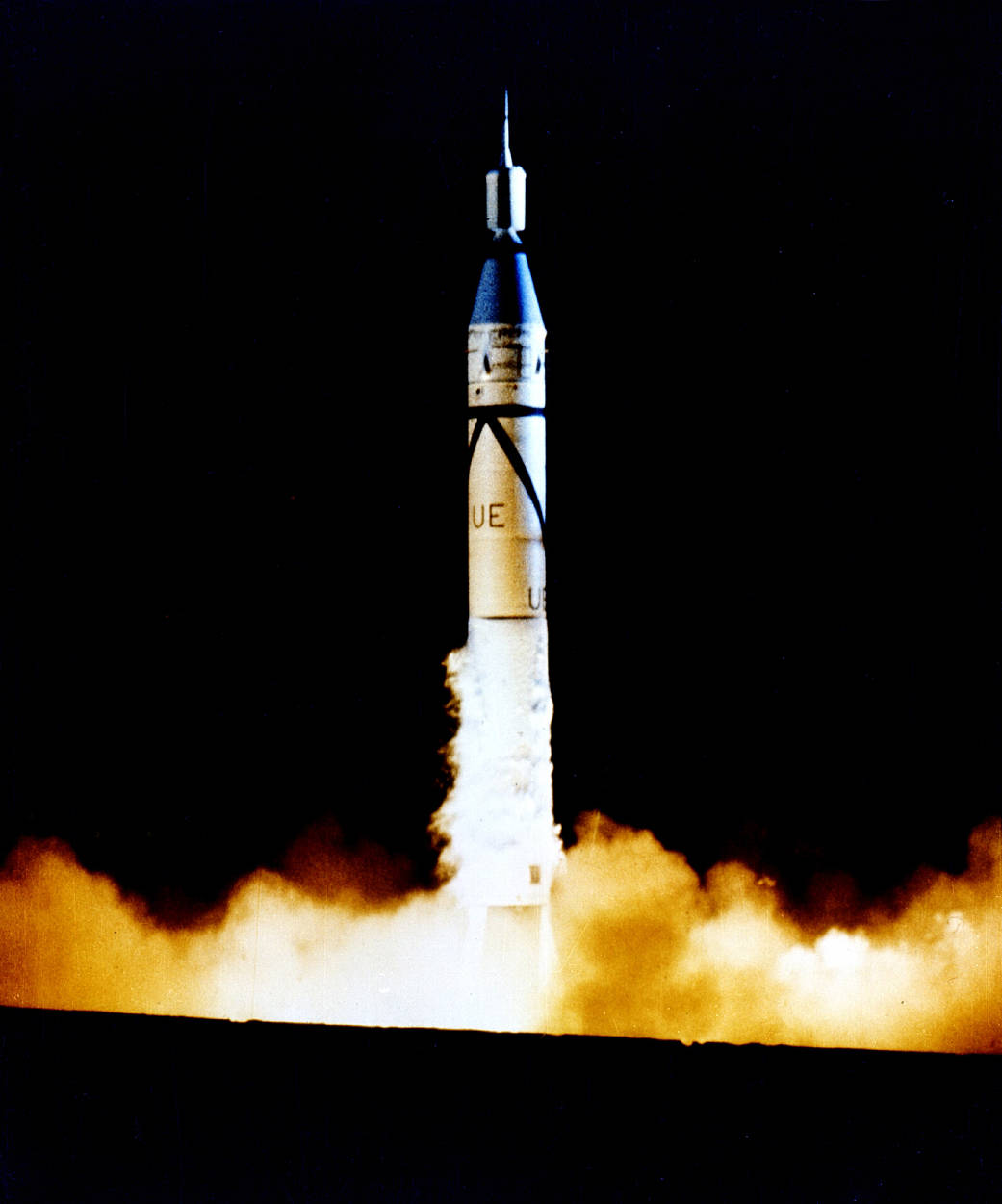
The prototype had a cone-shaped guidance section topped by a spinning tub that contained the upper-stage solid rocket motors, atop which sat the Explorer satellite.
The kit simulates this with the adapter. The short length of BT-5 fits over the adapter's BT-3 shaft to simulate the tub, and the top of the shaft is then shaped into the cone that held the Explorer satellite, which is in turn simulated with the dowel. The first step is to carve the upper part of the adapter to simulate the "step" visible below the tub. Using a nail file, this went pretty quickly.
Next, the centering rings are glued onto the upper shaft, and the BT-5 fits over those. Note that the centering ring sticks up a bit past the end of the BT-5 to simulate the rounded top of the tub.

Next, using the trusty nail file, we shape the balsa sticking up above the tub into a truncated cone.

After sanding one end of the dowel into an ogive point, we drill a shallow hole in the top of the cone and glue it in.

The nose cone is done, except for the filling and sanding. In the next installment, we'll build the main body tube.
I finally got enough free time to actually build the thing. We'll start with the obligatory group portrait of the kit contents.
The kit consists of a BT-50 main body tube, an 18mm motor mount; a set of parts that will be made into the nose cone (BT3 to BT50 adapter, a short length of BT-5, two 3-5 centering rings, and a short length of 1/8" hardwood dowel); sheet balsa for the fins; a printed cardstock sheet containing the body tube wrap, fin templates, and a couple of minor detail pieces; one the good Doctor's "trash bag" parachutes; shock cords; a launch lug; the most entertaining written instructions I've ever read; and a small bag containing the miscellaneous fiddly bits. This is definitely an "old school" builder's kit.
The prototype had a cone-shaped guidance section topped by a spinning tub that contained the upper-stage solid rocket motors, atop which sat the Explorer satellite.
The kit simulates this with the adapter. The short length of BT-5 fits over the adapter's BT-3 shaft to simulate the tub, and the top of the shaft is then shaped into the cone that held the Explorer satellite, which is in turn simulated with the dowel. The first step is to carve the upper part of the adapter to simulate the "step" visible below the tub. Using a nail file, this went pretty quickly.
Next, the centering rings are glued onto the upper shaft, and the BT-5 fits over those. Note that the centering ring sticks up a bit past the end of the BT-5 to simulate the rounded top of the tub.
Next, using the trusty nail file, we shape the balsa sticking up above the tub into a truncated cone.
After sanding one end of the dowel into an ogive point, we drill a shallow hole in the top of the cone and glue it in.
The nose cone is done, except for the filling and sanding. In the next installment, we'll build the main body tube.


