You are using an out of date browser. It may not display this or other websites correctly.
You should upgrade or use an alternative browser.
You should upgrade or use an alternative browser.
Ares-I build thread
- Thread starter BsSmith
- Start date


Help Support The Rocketry Forum:
This site may earn a commission from merchant affiliate
links, including eBay, Amazon, and others.

Fred22
Well-Known Member
- Joined
- Jan 5, 2009
- Messages
- 2,460
- Reaction score
- 7
I fixed the image file. Seems like I need to find a new place to put my pictures.
Glad you fixed it
") I think this could be a great thread and i am looking forward to following it
I think this could be a great thread and i am looking forward to following itCheers
fred
BsSmith
Well-Known Member
- Joined
- Jan 18, 2009
- Messages
- 807
- Reaction score
- 2
Thank you!
This build is going to be equally as interesting to me. I've made up several of the build techniques I'm going to use on this, none have been tested. The only way I'll know if they work is to put them on the rocket.
The biggest challenges of this is going to be the removable fins and the 4.5" tube. Looking at the rocket once it's done, you will never be able to tell that the fins are removable. All of the screws and separation points will be hidden under scale details. As for the 4.5" tube, I'll use 2-part foam to build up the surface from a standard 4" tube. Hopefully, this will give me a scale-like finish for the fuel tank as well.
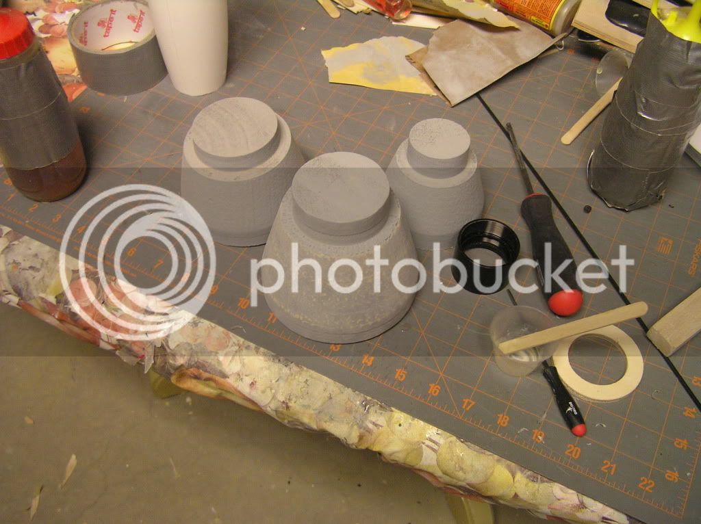
Right now, however, I am working on masters for the transition molds. The transitions I have right now are made of balsa right now. Through some miracle process, they will eventually be hollow fiberglass. The process of making the molds will most likely take a very long time, so this thread will go very slow for a while. I will post pictures as I go.
This build is going to be equally as interesting to me. I've made up several of the build techniques I'm going to use on this, none have been tested. The only way I'll know if they work is to put them on the rocket.
The biggest challenges of this is going to be the removable fins and the 4.5" tube. Looking at the rocket once it's done, you will never be able to tell that the fins are removable. All of the screws and separation points will be hidden under scale details. As for the 4.5" tube, I'll use 2-part foam to build up the surface from a standard 4" tube. Hopefully, this will give me a scale-like finish for the fuel tank as well.
Right now, however, I am working on masters for the transition molds. The transitions I have right now are made of balsa right now. Through some miracle process, they will eventually be hollow fiberglass. The process of making the molds will most likely take a very long time, so this thread will go very slow for a while. I will post pictures as I go.
ben_ullman
Well-Known Member
- Joined
- Jan 17, 2009
- Messages
- 1,523
- Reaction score
- 2
Thank you!
This build is going to be equally as interesting to me. I've made up several of the build techniques I'm going to use on this, none have been tested. The only way I'll know if they work is to put them on the rocket.
The biggest challenges of this is going to be the removable fins and the 4.5" tube. Looking at the rocket once it's done, you will never be able to tell that the fins are removable. All of the screws and separation points will be hidden under scale details. As for the 4.5" tube, I'll use 2-part foam to build up the surface from a standard 4" tube. Hopefully, this will give me a scale-like finish for the fuel tank as well.
Right now, however, I am working on masters for the transition molds. The transitions I have right now are made of balsa right now. Through some miracle process, they will eventually be hollow fiberglass. The process of making the molds will most likely take a very long time, so this thread will go very slow for a while. I will post pictures as I go.
you can buy 4.5" tubing. Talk to Wildman or Liberty Launch systems. PR made some and they should be able to get it. If not I have 5 x 4.5" couplers that you can join with 4" BT and make a fiberglass BT out of the manual way.
That is what I was going to do for a 1/4th scale Terrier Nike (and might still)
Ben
BsSmith
Well-Known Member
- Joined
- Jan 18, 2009
- Messages
- 807
- Reaction score
- 2
you can buy 4.5" tubing. Talk to Wildman or Liberty Launch systems. PR made some and they should be able to get it. If not I have 5 x 4.5" couplers that you can join with 4" BT and make a fiberglass BT out of the manual way.
That is what I was going to do for a 1/4th scale Terrier Nike (and might still)
Ben
Eh.. Good option, but I'll go with the foam, just because I think it will look better if it turns out right. Plus I already have the 4" tubing.
If the foam fails, I have something that I can fall back on now. Then it'll be an Ares-I X.
One thing I forgot to mention in the other post... This rocket will most likely need it's own special launch pad. I'll be putting the rail buttons on the upper section to make it look better. Because of that, the base of the rocket will need to sit farther down (3-4') in relation to the launch rail.
ScrapDaddy
Well-Known Member
- Joined
- Jan 26, 2010
- Messages
- 2,083
- Reaction score
- 4
Since you Are a high power flyer (and not to be a sterotype here) why not invest some cash into gismos that move the motor like in the real Aries rocket?that way you can launch out of a tube launcher
BsSmith
Well-Known Member
- Joined
- Jan 18, 2009
- Messages
- 807
- Reaction score
- 2
Since you Are a high power flyer (and not to be a sterotype here) why not invest some cash into gismos that move the motor like in the real Aries rocket?
$$$$$$$$$$$$$$$$$$$$$$$$$$$$$$$$$$$$$$$$$$$$$$$ we're talking about thousands of dollars. A L3 project would cost less.
Plus, making that system in extreme miniature will be very, very, very,very, very, very, very, very, very, very, very, very, very, very, very, very, very, very, very, very, very, very, very, very, very, very, very, very, very, very, very, very, very, very, very, very difficult.
ben_ullman
Well-Known Member
- Joined
- Jan 17, 2009
- Messages
- 1,523
- Reaction score
- 2
Since you Are a high power flyer (and not to be a sterotype here) why not invest some cash into gismos that move the motor like in the real Aries rocket?that way you can launch out of a tube launcher
Ok, your talking about 2 unrelated things here.
Controlling the ascent of a rocket is unallowed per TRA/NAR rules.
Launching out of a tube launcher is dumb for something this large.
Bsmith, one thing you could try is to just put the buttons on the aft of the rocket and use a standoff on the rail. Because having the buttons at the top you wont have as much stability, if you put them at the bottom and use a standoff on the rail to keep it from hitting the fatter upper section you may get more time utilizing the buttons. Im not sure of the rockets measurements so im not sure which would be better.
Ben
ScrapDaddy
Well-Known Member
- Joined
- Jan 26, 2010
- Messages
- 2,083
- Reaction score
- 4
well at Narcon 48 a man had a computer gismo that had a self stabilizing computer, it would correct the angle of thrust for whatever shift there was in the rockets movement
ben_ullman
Well-Known Member
- Joined
- Jan 17, 2009
- Messages
- 1,523
- Reaction score
- 2
well at Narcon 48 a man had a computer gismo that had a self stabilizing computer, it would correct the angle of thrust for whatever shift there was in the rockets movement
are you talking about gyros? this is a topic for another thread. (im sure one will pop up in a few mins
)Ben
ScrapDaddy
Well-Known Member
- Joined
- Jan 26, 2010
- Messages
- 2,083
- Reaction score
- 4
what section should i put that in?are you talking about gyros? this is a topic for another thread. (im sure one will pop up in a few mins
Ben
ben_ullman
Well-Known Member
- Joined
- Jan 17, 2009
- Messages
- 1,523
- Reaction score
- 2
Last edited by a moderator:
ScrapDaddy
Well-Known Member
- Joined
- Jan 26, 2010
- Messages
- 2,083
- Reaction score
- 4
Last edited by a moderator:
ScrapDaddy
Well-Known Member
- Joined
- Jan 26, 2010
- Messages
- 2,083
- Reaction score
- 4
$$$$$$$$$$$$$$$$$$$$$$$$$$$$$$$$$$$$$$$$$$$$$$$ we're talking about thousands of dollars. A L3 project would cost less.
Plus, making that system in extreme miniature will be very, very, very,very, very, very, very, very, very, very, very, very, very, very, very, very, very, very, very, very, very, very, very, very, very, very, very, very, very, very, very, very, very, very, very, very difficult.
well dont HPR flyers spend $200 dollars a launch?
BsSmith
Well-Known Member
- Joined
- Jan 18, 2009
- Messages
- 807
- Reaction score
- 2
Bsmith, one thing you could try is to just put the buttons on the aft of the rocket and use a standoff on the rail. Because having the buttons at the top you wont have as much stability, if you put them at the bottom and use a standoff on the rail to keep it from hitting the fatter upper section you may get more time utilizing the buttons. Im not sure of the rockets measurements so im not sure which would be better.
Ben
That is by far the easiest option, but both my dad and me agree that it would look far better without the 2" standoffs on the lower section. I'm also not sure if 2" standoffs can support the torque of such a large rocket.
BsSmith
Well-Known Member
- Joined
- Jan 18, 2009
- Messages
- 807
- Reaction score
- 2
For those interested, here is an image of the Rocksim rocket.
One thing that worries me about the rocket is getting the correct length. The measurements I got from a drawing of the Ares-IX are completely different from the ones I got from a drawing of the Ares-I. In this scale, the Ares-I is over a foot shorter than the Ares-IX. Surprisingly, though, the measurements for the transitions are dead-on to each other.
The file I have now is for the Ares-I- does the rocket look too short for you, or does it look about right?
ben_ullman
Well-Known Member
- Joined
- Jan 17, 2009
- Messages
- 1,523
- Reaction score
- 2
That is by far the easiest option, but both my dad and me agree that it would look far better without the 2" standoffs on the lower section. I'm also not sure if 2" standoffs can support the torque of such a large rocket.
I was afraid I would be misunderstood!
Use buttons flush to the lower BT and use a standoff on the rail. Like a 2x4 against the bottom of the rocket. Because you might have more guidance using buttons lower than higher.
Ben
BsSmith
Well-Known Member
- Joined
- Jan 18, 2009
- Messages
- 807
- Reaction score
- 2
Hmm.. good idea
and the standoff would just fall away once it leaves the rail? There would probably be a danger of the standoff taking out the gimbal shroud though. I'll look into it.
One thing I probably want to avoid is putting any rail button below the leading edge of the fin, because that entire section of tubing will be completely removable and held in place by very tiny screws and about a 1/2" section of coupler on the top.
The rocket will be made with Blue Tube, but that section will still be iffy structure-wise.
ScrapDaddy
Well-Known Member
- Joined
- Jan 26, 2010
- Messages
- 2,083
- Reaction score
- 4
here is a crazy idea, how about fly-away rail guides?
ben_ullman
Well-Known Member
- Joined
- Jan 17, 2009
- Messages
- 1,523
- Reaction score
- 2
Hmm.. good idea
and the standoff would just fall away once it leaves the rail? There would probably be a danger of the standoff taking out the gimbal shroud though. I'll look into it.
One thing I probably want to avoid is putting any rail button below the leading edge of the fin, because that entire section of tubing will be completely removable and held in place by very tiny screws and about a 1/2" section of coupler on the top.
The rocket will be made with Blue Tube, but that section will still be iffy structure-wise.
The standoff would pose no problem to the operation of the actual rocket.how long is the bottom section before it transitions?
Sounds like a great plan and design. Its something that was on my future builds list
here is a crazy idea, how about fly-away rail guides?
no.
ScrapDaddy
Well-Known Member
- Joined
- Jan 26, 2010
- Messages
- 2,083
- Reaction score
- 4
ben_ullman
Well-Known Member
- Joined
- Jan 17, 2009
- Messages
- 1,523
- Reaction score
- 2
Thanks for being blunt
Well, you need to be able to have them anchored and hole the weight of the rocket while also come off. The only way I know how you would do that is using some small drilled out nylon bolts with some Bp and an Ematch. The hobby version of explosive bolts.
google for the Delta III flight, troj (kevin) was a club member, he might chime in with a link.
Ben
ScrapDaddy
Well-Known Member
- Joined
- Jan 26, 2010
- Messages
- 2,083
- Reaction score
- 4
I didnt mean those i meant....... One sec for the linkhttps://www.apogeerockets.com/education/downloads/Newsletter243.pdf
Last edited:
BsSmith
Well-Known Member
- Joined
- Jan 18, 2009
- Messages
- 807
- Reaction score
- 2
The entire 3" section is 35" long before it transitions. I don't have a final fin layout yet, but the removable section will most likely be 8-10" long. Once the length of the section is taken out, the MMT only has about 6" of tubing that it will glue into. It will be completely fine, with more than enough strength to take even a K, but there will only be enough room to put one button. After that, the other button will most likely be in the drouge bay.
no
I didnt mean those i meant....... One sec for the linkhttps://www.apogeerockets.com/educati...sletter243.pdf
no
ben_ullman
Well-Known Member
- Joined
- Jan 17, 2009
- Messages
- 1,523
- Reaction score
- 2
The entire 3" section is 35" long before it transitions. I don't have a final fin layout yet, but the removable section will most likely be 8-10" long. Once the length of the section is taken out, the MMT only has about 6" of tubing that it will glue into. It will be completely fine, with more than enough strength to take even a K, but there will only be enough room to put one button. After that, the other button will most likely be in the drouge bay.
so use a 4 foot rail with a 1 foot stand off. That would give you more guidance than a 6 foot rail with the buttons up top. Is what im describing making any sense? because the farthe towards the nose the buttons are the more rail you need for them to be affective.
Ben
BsSmith
Well-Known Member
- Joined
- Jan 18, 2009
- Messages
- 807
- Reaction score
- 2
Yeah, what your describing makes sense, but I don't think what I described makes sense to you.
The blast deflector for the pad I'm talking about would be 3 feet below where the rail starts. Because of this, when the rocket sits on an 8 foot rail, the buttons will still travel 8 feet on the rail. If the rocket sat on a normal pad, the buttons would only travel 5 of the 8 feet.
I think this might be what your talking about in "effectiveness." The buttons can be as far foward as you want them to be, you just have to have a rail long enough to let the rocket come up to speed. The pad design I have will just set the rocket down further on the rail, giving it enough room to gain enough speed.
ben_ullman
Well-Known Member
- Joined
- Jan 17, 2009
- Messages
- 1,523
- Reaction score
- 2
Yeah, what your describing makes sense, but I don't think what I described makes sense to you.
The blast deflector for the pad I'm talking about would be 3 feet below where the rail starts. Because of this, when the rocket sits on an 8 foot rail, the buttons will still travel 8 feet on the rail. If the rocket sat on a normal pad, the buttons would only travel 5 of the 8 feet.
I think this might be what your talking about in "effectiveness." The buttons can be as far foward as you want them to be, you just have to have a rail long enough to let the rocket come up to speed. The pad design I have will just set the rocket down further on the rail, giving it enough room to gain enough speed.
ok I understand your pad design. My idea would make it so you could fly off any rail anytime. But your mod doesnt sound like that big of an issue anyways.
Cant wait to see this progress! sounds sweet!
Ben
Similar threads
- Replies
- 10
- Views
- 993
- Replies
- 11
- Views
- 794