Orbital space is 25 times harder than suborbital

The Rocketry Forum

Help Support The Rocketry Forum:

This site may earn a commission from merchant affiliate links, including eBay, Amazon, and others.

RGClark

Mathematician
Joined
Aug 25, 2017
Messages
315
Reaction score
31
Location
Philadelphia, PA USA
No. Going from suborbital to orbital is another whole ball of wax. Its much more complex and requires a lot more control. And then using it to launch a payload? Considerably more complex. Just ask Blue Origin. Bezos has pretty much unlimited money and hasn't gone orbital yet. That's a big step of engineering.

Actually, not. It’s commonly said that orbital space is 25 times harder than suborbital space because of the energy requirements. But that’s if you want to carry the same mass in payload.

But in actuality you don’t build an orbital rocket like that. With staging, the final mass that reaches orbit is far smaller than the payload mass of the suborbital rocket. In fact, the cost of the first stage is the greatest cost of the orbital launcher. So once you build that and successfully accomplish staging at high altitude, near vacuum, you’ve accomplished the most difficult parts of reaching orbit.

That’s just getting to orbit. For precise orbital location that’s another set of steps that needs to be done. But just getting to orbit you can just use a spin-stabilized stage. In fact that was what was used for the first orbital rocket of the the U.S. to launch the satellite Explorer 1.

Bob Clark
 
That doesn’t mean it’s wrong.

Bob Clark ;)
You are wrong. People have been telling you this on here, on reddit, and on the arocket email list every single time you show up with these proposals.

Why don’t we go through this article line by line, and see what there is to see.

image.png

Making a good composite case is hard. You not only need to contain the pressure of the motor, you also need to keep the heat from getting the casing too hot. This is a tricky problem, and while it is solvable, it isn’t trivial. You have a habit of assuming many things that are very difficult are in fact easy, and then ignoring them.

image.png


Let’s get into the meat of the article now. You chose the Cesaroni O8000 as the basis for your analysis. This is actually a suboptimal motor for high performance flights, due to several factors, including relatively low isp, poor mass ratio because of the overly thick casing, and a large frontal area for the amount of impulse it has. I’ll include it in this analysis, but I’ll also throw in a few motors which I think would be superior options. The Aerotech O5280 is a 98mm motor in a composite casing that uses a high isp propellant. The Cesaroni N5800 is another 98mm motor with a high performance propellant, although it uses aluminum hardware. The Cesaroni O3400 fits more impulse into the same casing as the N5800, it uses a high density propellant that gives a high mass ratio, but relatively low isp. Finally the Aerotech M2050 is a 75mm diameter motor that uses the same propellant as the O5280, it has the highest isp of any commercially available amateur motor.

You decided that a carbon fiber casing could achieve a mass ratio of 0.8. I talked with some people I know who are developing carbon fiber motor casings, and they said that a carbon case could reduce the dry mass of some commercial solid motors by around 50%. While I doubt that a mass ratio of 0.8 is possible at amateur sizes and budgets, I ran the numbers for all of the motors at that mass ratio as well.

image.png

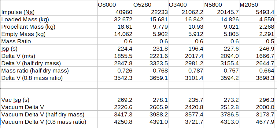
Next, you chose a vacuum isp of 285s for your motors. This is an unreasonable assumption. As stated previously, the O8000 doesn’t use a high isp propellant. I ran some simulations in Openmotor with a motor similar to the ones I was evaluating, and when changing the exit pressure to a vacuum, and enlarging the nozzle exit, I saw about a 20% increase in isp. This seems to match what I’ve been able to find for performance on motors used in industry. Here is the first part of my spreadsheet, with the isp and delta V calculated for each motor, at the stock hardware mass, half hardware mass, and a 0.8 mass fraction.

image.png


Note that while most of the motors aren’t matching your 285s estimate, the M2050 is actually significantly above it, at 296s.
Now we get to the fun part. You didn’t calculate the delta V of any of your proposals. You came up with your numbers, and then plugged them into a launch performance calculator. A launch performance calculator that according to it’s own documentation does not properly consider aerodynamic drag losses from a high thrust to weight ratio rocket. This has been pointed out to you before, and yet you keep on showing off this flawed analysis. For a math professor, you seem to be allergic to running the actual calculations yourself. So let’s calculate the Delta V of each of the motors, at each of the different mass ratios (stock, half casing mass, and 0.8) for both the single motors, and your proposed launch vehicle and see what we get.

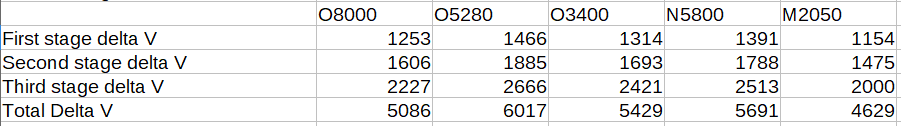
Conventional wisdom is that LEO has a delta V requirement of about 9.4 km/s. I followed the article and made each stage four times the mass of the one above it. I used the vacuum isp for the upper two stages, and the sea level isp for the first stage. The first three rows of the results show the delta V contribution of each stage to the total stack, and the final row is the total delta V of the stack.

First here are the results for a vehicle with unmodified casing masses. The O5280 is the clear winner here, with a calculated delta V of just over 6 km/s. The N5800 and O3400 come a little ways behind, followed by the O8000 and the M2050. The M2050 suffers from a comparatively poor mass ratio, due to a rather thick casing, and the square cube law. Smaller motors will tend to have worse mass ratios, since they have more surface area for their propellant volume.
image.png


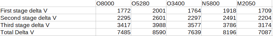
Moving on to calculating delta V for motors with the dry mass halved. The O5280 is the clear leader at almost 8.6 km/s. It’s already a composite cased motor with a relatively high mass fraction, so I doubt that you can cut the casing mass in half by replacing fiberglass with carbon fiber.
image.png


Finally we have the numbers for when the motors are set to the 0.8 mass ratio specified in the article. Since we’re disregarding the initial hardware masses, this ends up just being an isp contest that the M2050 handily wins. It’s also the only configuration to break 9.4 km/s.
image.png


Now comes the elephant in the room. These mass ratios are impossible. You have a habit of disregarding all component masses besides the motor mass. This is wrong. An orbital rocket will require many more systems beyond just the motors. It will need control systems, whether those take the form of a gimbaled nozzle, RCS thrusters, or actuated fins on the first stage. It will need avionics to control those systems to keep it on course. It will need a structure to hold all of these things, and to couple the stages together. It will need a fairing to protect the payload from the atmosphere on the way up. Hell, I didn't even include a gram of payload mass. These calculations are for an unguided stack of motors, not a launch vehicle. A single solid rocket motor with a mass ratio of 0.8 might be possible for a very experienced amateur motor maker really pushing the limits of what’s possible in the hobby. A mass ratio of 0.8 for an entire vehicle is impossible to do at the amateur scale. You have neglected to consider any factors at all besides raw propulsion numbers. There is far more to building an orbital launch vehicle than building something that meets the theoretical delta V requirements.

There’s also the fact that the 9.4 km/s delta V requirement that I’ve been using is likely to be a major underestimate. Accelerating to high speeds within the lower atmosphere will send your drag losses through the roof. You have been told this multiple times before, and yet you keep on trotting out this article as proof that orbital rockets are easy.

image.png


Next, let’s look at the proposed vehicle design. You suggest clustering the motors in the first and second stage. This runs into a square cube law problem, where a cluster of smaller motors will have a worse mass ratio and performance than a single large motor of the same impulse.

image.png


Then we have the part that shows your ignorance about solid rocket motor design. You correctly identify that ignition of 16 motors in the first stage is difficult. The proposed solution of combining four motors into one long motor is patently absurd. While I haven’t made any motors yet, I have spent a fair amount of time talking with people and running simulations in Openmotor. Long motors are hard. Making a motor twice as long as the O8000 or M2050 might be possible, because they are relatively short. It would probably require increasing the core diameter of the bottom grains, which would reduce propellant mass. But extending that to triple or quadruple the length of the initial motor is frankly impossible for amateur motor makers.

image.png


And then at last we have the costs. Your entire budget for a launch in the article is $63,000, which solely comes from the O8000 motors. The budget does not include the carbon fiber casings. It does not include any of the other subsystems I mentioned earlier. It does not include the cost of the tools and machinery to build the rocket. It does not include the cost of building a launcher. It does not include the cost of using the launch site. It does not include the cost of labor. In the end the $63,000 cost of propellant is going to be a relatively small proportion of the cost of an orbital launch.

Finally, let’s take a look at what it takes to launch a cubesat into orbit with solid rocket motors. The Japanese SS-520 sounding rocket with a third stage placed a cubesat into orbit in 2018. The SS-520 rocket weighs 2,600 kg, and at 0.52m in diameter is significantly larger than any amateur rocket I’ve ever heard of. The SS-520 is tiny in comparison to other orbital rockets, but it is well outside the realm of what’s possible for an amateur group.
 
You can get a cube sat into orbit for about $30,000. A suborbital project like kips probably cost about $3K all in. So orbital is 10x harder than suborbital.
 
"Every idea, every suggestion, every hypothesis, every claim sounds reasonable...until you do the math" -- The Prfesser ;)

Neutron95 has clearly demonstrated the difficulty with wild claims. It took him a lot of explanation to overturn a claim that took SmilinBob just a few seconds to copy and paste. And of course the claim---and not the science/technology that debunks it---is what people remember. :(:rolleyes:
 
“It is not the critic who counts; not the man who points out how the strong man stumbles, or where the doer of deeds could have done them better. The credit belongs to the man who is actually in the arena, whose face is marred by dust and sweat and blood; who strives valiantly; who errs, who comes short again and again, because there is no effort without error and shortcoming; but who does actually strive to do the deeds; who knows great enthusiasms, the great devotions; who spends himself in a worthy cause; who at the best knows in the end the triumph of high achievement, and who at the worst, if he fails, at least fails while daring greatly, so that his place shall never be with those cold and timid souls who neither know victory nor defeat.”
Teddy Roosevelt

I just wonder what Kip will do next, because he nailed this one. 😁
Thanks Steve. I was just about to ignore this thread.
 
Thanks for the response.
You are wrong. People have been telling you this on here, on reddit, and on the arocket email list every single time you show up with these proposals.

Why don’t we go through this article line by line, and see what there is to see.

image.png

.

Thanks for the informative response, Neutron95. You are right the SilverbirdAstronautics.com payload estimator is too inaccurate for high T/W rockets to be relied on for the payload possible. I’ll give a calculation that‘ll give an estimate for achieving orbital velocity at the altitude for space of 100km.

The USC rocketry team did not give what propellant fraction they were able to achieve using carbon fiber casing for their Traveler IV rocket that reached 100km. We can probably estimate it though given the maximum velocity and altitude reached, and using reasonable estimates for propellant load and payload.

But a 80% propellant fraction is not particularly high for industry standard solid rocket motors: 90% is common for the solid rocket boosters used in the industry for orbital rockets, and even 95% has been reached.

But for propellant fractions that have been achieved by amateurs using carbon fiber casing, the only one I’ve seen is 63.7% by the Princeton Spaceshot team for their booster stage. I’ll give a calculation for that propellant fraction case as well in a follow up.

As I do think 80% is achievable by amateur teams I’ll use that number in this calculation.

The vacuum Isp for an propellant combination is very largely determined by the expansion ratio. So the 296s vacuum Isp you cited for the M-class motor would be achievable also for the other APCP motors with longer nozzles. I’ll use that vacuum Isp number for my upper stages that will only be firing at high altitude, near vacuum.

The tangential orbital velocity is ~7,800 m/s. But if you launch from a low latitude site such as the Cape you get ~400 m/s for free from the Earth’s rotation. So you only need actually to produce ~7,400 m/s horizontal velocity. I’ll use four stages for this calculation. For the first stage, I’ll use the SpaceLoft rocket as the first stage to first loft the upper stages to the 100 km altitude for space. Then the other stages will be firing horizontally to reach the ~7,400 m/s.

I’ll spilt the ~7,400 m/s into 3 equal parts so ~2,460 m/s for each stage.

For the top stage, i.e, 4th stage, let it use a 4 kg propellant load and 1 kg dry mass. Take the payload as 2 kg. Then with a 296s vacuum Isp this can get a vacuum delta-v of:

296*9.81Ln(1 + 4/(1 + 2)) = 2,460 m/s.

Note the ratios here of propellant mass, to dry mass, to payload mass of 4:1:2. If you keep this same ratio at each stage then each stage will get 2,460 m/s delta-v. For the next below stage, i.e., 3rd stage, use the top stage total mass of 7 kg for its payload, then with the same 4:1:2 ratio:

296*9.81Ln(1 + 14/(3.5 + 7)) = 2,460 m/s.

Then for the stage below that, i.e., the 2nd stage, use the 3rd stage total mass of 24.5 kg as its payload and again the 4:1:2 ratio. Then:

296*9.81Ln(1 + 49/(12.25 + 24.5)) = 2,460 m/s.

These three upper stages with the 2 kg payload that reach’s orbit have a total mass of 85.75 kg.

The SpaceLoft motor has motor mass only, that is excluding the payload section, of 234 kg, and can get a maximum of 120 kg to over 100 km. So you use this as the first stage to get the 85.75 kg total mass of the upper stages to the 100 km altitude for space.

The total of all 4 stages is ~320 kg. So the proportion of rocket gross mass to orbital payload is ~320 kg to 2 kg, about 160 to 1.

Actually since SpaceLoft can get 120 kg to 100 km. We can scale up our orbital payload and stages a bit: 120 kg is bigger than 85.75 kg by a factor of 1.4. So scaling up our upper stages by the same ratio, we can get a payload of 1.4*2 =2.8 kg to orbit.

Note though this is an underestimate because the first stage is only firing straight up; so is only giving altitude to the upper stages. This is not the most efficient use of a first stage. Typically the first stage also contributes some horizontal velocity to the upper stages so the actual orbital payload will be somewhat more.

Bob Clark
 
Thanks for the response.


Thanks for the informative response, Neutron95. You are right the SilverbirdAstronautics.com payload estimator is too inaccurate for high T/W rockets to be relied on for the payload possible. I’ll give a calculation that‘ll give an estimate for achieving orbital velocity at the altitude for space of 100km.

The USC rocketry team did not give what propellant fraction they were able to achieve using carbon fiber casing for their Traveler IV rocket that reached 100km. We can probably estimate it though given the maximum velocity and altitude reached, and using reasonable estimates for propellant load and payload.

But a 80% propellant fraction is not particularly high for industry standard solid rocket motors: 90% is common for the solid rocket boosters used in the industry for orbital rockets, and even 95% has been reached.

But for propellant fractions that have been achieved by amateurs using carbon fiber casing, the only one I’ve seen is 63.7% by the Princeton Spaceshot team for their booster stage. I’ll give a calculation for that propellant fraction case as well in a follow up.

As I do think 80% is achievable by amateur teams I’ll use that number in this calculation.

The vacuum Isp for an propellant combination is very largely determined by the expansion ratio. So the 296s vacuum Isp you cited for the M-class motor would be achievable also for the other APCP motors with longer nozzles. I’ll use that vacuum Isp number for my upper stages that will only be firing at high altitude, near vacuum.

The tangential orbital velocity is ~7,800 m/s. But if you launch from a low latitude site such as the Cape you get ~400 m/s for free from the Earth’s rotation. So you only need actually to produce ~7,400 m/s horizontal velocity. I’ll use four stages for this calculation. For the first stage, I’ll use the SpaceLoft rocket as the first stage to first loft the upper stages to the 100 km altitude for space. Then the other stages will be firing horizontally to reach the ~7,400 m/s.

I’ll spilt the ~7,400 m/s into 3 equal parts so ~2,460 m/s for each stage.

For the top stage, i.e, 4th stage, let it use a 4 kg propellant load and 1 kg dry mass. Take the payload as 2 kg. Then with a 296s vacuum Isp this can get a vacuum delta-v of:

296*9.81Ln(1 + 4/(1 + 2)) = 2,460 m/s.

Note the ratios here of propellant mass, to dry mass, to payload mass of 4:1:2. If you keep this same ratio at each stage then each stage will get 2,460 m/s delta-v. For the next below stage, i.e., 3rd stage, use the top stage total mass of 7 kg for its payload, then with the same 4:1:2 ratio:

296*9.81Ln(1 + 14/(3.5 + 7)) = 2,460 m/s.

Then for the stage below that, i.e., the 2nd stage, use the 3rd stage total mass of 24.5 kg as its payload and again the 4:1:2 ratio. Then:

296*9.81Ln(1 + 49/(12.25 + 24.5)) = 2,460 m/s.

These three upper stages with the 2 kg payload that reach’s orbit have a total mass of 85.75 kg.

The SpaceLoft motor has motor mass only, that is excluding the payload section, of 234 kg, and can get a maximum of 120 kg to over 100 km. So you use this as the first stage to get the 85.75 kg total mass of the upper stages to the 100 km altitude for space.

The total of all 4 stages is ~320 kg. So the proportion of rocket gross mass to orbital payload is ~320 kg to 2 kg, about 160 to 1.

Actually since SpaceLoft can get 120 kg to 100 km. We can scale up our orbital payload and stages a bit: 120 kg is bigger than 85.75 kg by a factor of 1.4. So scaling up our upper stages by the same ratio, we can get a payload of 1.4*2 =2.8 kg to orbit.

Note though this is an underestimate because the first stage is only firing straight up; so is only giving altitude to the upper stages. This is not the most efficient use of a first stage. Typically the first stage also contributes some horizontal velocity to the upper stages so the actual orbital payload will be somewhat more.

Bob Clark


Bob , a extra 5 percent mass fraction gain on a motor means nothing if your rocket is 10 percent over optimal mass. It would be great if we could just launch motors , but sadly no , you need to use mor then just a motor. USC has always published all its numbers , including mass .

Oh one last point , no unguided space shot rocket ever gets launch vertical , I figured you would have known that.


Eric
 
I used to work with a couple of "Physicists" who often got confused with the math. :) But they thought they knew everything, which made life hard for the rest of us. After one made the "add acid" error, my boss realized these guys were dangerous. Those were the guys that wanted to cast their own teflon, lol. One wanted to use methylmercury in an experiment in the MRI machine we were working with. :)
The only really cool thing I learned from the MR stuff was that positrons can be detected in air 60" outside the bore;)(positrons were from a F-18 radioactive tracer). And that PCboards with copper thicker than 8mils will melt off the board. :) Eddy currents are substantial, lol.
 
Finally, let’s take a look at what it takes to launch a cubesat into orbit with solid rocket motors. The Japanese SS-520 sounding rocket with a third stage placed a cubesat into orbit in 2018. The SS-520 rocket weighs 2,600 kg, and at 0.52m in diameter is significantly larger than any amateur rocket I’ve ever heard of. The SS-520 is tiny in comparison to other orbital rockets, but it is well outside the realm of what’s possible for an amateur group.

I am impressed that you went to so much effort to reply to a well known crank; you deserve credit for that effort, even if it is wasted on Smilin' Bob.

I'd like--if possible--to move this discussion toward actual mass fractions as achieved by amateur builders:

My six inch by 60" stages are coming in at just below 60% propellant (using a not fully aluminum loaded propellant). My 9 inch by 84" stage--for which I have actual weights--will come in at a slightly lower propellant fraction than the 6 inch motor (using the same propellant) because the required wall thickness jumps from 0.125" to 0.250". In both cases, the aluminum tube is the single largest contribution to dry mass. I have some parts (tubes, forward bulkheads) for a 12" by 120" motor; using CAD based weight estimates for the not yet built bits, I am showing slightly over 60% propellant fraction for that stage, largely because the tube wall remains at 0.250".

I've looked at both Titanium (Grade 5) tubing and carbon fiber. The former--for the six inch stage--will bring the propellant fraction up to just over 61%; however, that tubing in the required wall thickness in not available. Flow forming that tubing has an about $10K setup cost and then the cost of material and a bit more per tube; for the half dozen tubes that I probably would never get through, that appears to work out to about $1500 per tube...about 10x the cost of the current aluminum tube. In addition, the thin wall on the Titanium tubing would require going to button head fasteners rather than the current countersunk, meaning drag would be significantly higher.

A friend has privately and without any commitment suggested that he could make a carbon fiber tube in 6 inch by 60" dimension including an aerospace grade propellant liner for about $3000 per unit. That would get propellant fraction up to about 63% if no other piece parts changed. As with the Titanium tubing, the much thinner wall would present problems with fasteners; in this case that would most likely be met by using thicker walls at the required locations, those thicker walls would reduce the propellant fraction back toward 61%.

Can others comment on what sort of actual propellant fractions they are seeing in built stages?

Bill
 
Last edited:
Thanks for the response.


Thanks for the informative response, Neutron95. You are right the SilverbirdAstronautics.com payload estimator is too inaccurate for high T/W rockets to be relied on for the payload possible. I’ll give a calculation that‘ll give an estimate for achieving orbital velocity at the altitude for space of 100km.

The USC rocketry team did not give what propellant fraction they were able to achieve using carbon fiber casing for their Traveler IV rocket that reached 100km. We can probably estimate it though given the maximum velocity and altitude reached, and using reasonable estimates for propellant load and payload.

But a 80% propellant fraction is not particularly high for industry standard solid rocket motors: 90% is common for the solid rocket boosters used in the industry for orbital rockets, and even 95% has been reached.

But for propellant fractions that have been achieved by amateurs using carbon fiber casing, the only one I’ve seen is 63.7% by the Princeton Spaceshot team for their booster stage. I’ll give a calculation for that propellant fraction case as well in a follow up.

As I do think 80% is achievable by amateur teams I’ll use that number in this calculation.

The vacuum Isp for an propellant combination is very largely determined by the expansion ratio. So the 296s vacuum Isp you cited for the M-class motor would be achievable also for the other APCP motors with longer nozzles. I’ll use that vacuum Isp number for my upper stages that will only be firing at high altitude, near vacuum.

The tangential orbital velocity is ~7,800 m/s. But if you launch from a low latitude site such as the Cape you get ~400 m/s for free from the Earth’s rotation. So you only need actually to produce ~7,400 m/s horizontal velocity. I’ll use four stages for this calculation. For the first stage, I’ll use the SpaceLoft rocket as the first stage to first loft the upper stages to the 100 km altitude for space. Then the other stages will be firing horizontally to reach the ~7,400 m/s.

I’ll spilt the ~7,400 m/s into 3 equal parts so ~2,460 m/s for each stage.

For the top stage, i.e, 4th stage, let it use a 4 kg propellant load and 1 kg dry mass. Take the payload as 2 kg. Then with a 296s vacuum Isp this can get a vacuum delta-v of:

296*9.81Ln(1 + 4/(1 + 2)) = 2,460 m/s.

Note the ratios here of propellant mass, to dry mass, to payload mass of 4:1:2. If you keep this same ratio at each stage then each stage will get 2,460 m/s delta-v. For the next below stage, i.e., 3rd stage, use the top stage total mass of 7 kg for its payload, then with the same 4:1:2 ratio:

296*9.81Ln(1 + 14/(3.5 + 7)) = 2,460 m/s.

Then for the stage below that, i.e., the 2nd stage, use the 3rd stage total mass of 24.5 kg as its payload and again the 4:1:2 ratio. Then:

296*9.81Ln(1 + 49/(12.25 + 24.5)) = 2,460 m/s.

These three upper stages with the 2 kg payload that reach’s orbit have a total mass of 85.75 kg.

The SpaceLoft motor has motor mass only, that is excluding the payload section, of 234 kg, and can get a maximum of 120 kg to over 100 km. So you use this as the first stage to get the 85.75 kg total mass of the upper stages to the 100 km altitude for space.

The total of all 4 stages is ~320 kg. So the proportion of rocket gross mass to orbital payload is ~320 kg to 2 kg, about 160 to 1.

Actually since SpaceLoft can get 120 kg to 100 km. We can scale up our orbital payload and stages a bit: 120 kg is bigger than 85.75 kg by a factor of 1.4. So scaling up our upper stages by the same ratio, we can get a payload of 1.4*2 =2.8 kg to orbit.

Note though this is an underestimate because the first stage is only firing straight up; so is only giving altitude to the upper stages. This is not the most efficient use of a first stage. Typically the first stage also contributes some horizontal velocity to the upper stages so the actual orbital payload will be somewhat more.

Bob Clark
If I may direct you to the datasheet Aerotech has published for a version of Propellant X, you'll see a figure I've underlined. That is the theoretical Isp a motor using this propellant could have, at 1000 psi chamber pressure, under the theoretical conditions. So no implementation losses like nozzle exit inefficiency, incomplete combustion, heat sunk into the casing, heat sunk into ablating the thermal liner. No motor using this propellant at this chamber pressure can achieve an Isp above the ~290s figure.

Running higher chamber pressures would net a higher Isp, but you pay for that by needing heavier hardware to withstand the higher pressures, eating into your propellant mass fraction.

Propellant X is as close to Space Shuttle SRB propellant as you can get within the hobby motor space, with the highest c* x density.
If you want more performance out of your propellant you'd need to start mixing your own experimental formula and casting your own propellant grains, which is a whole can of beans to do repeatably, not to mention you're trying outdo the performance of a formula like Propellant X.

There's a litany of considerations that go into developing a propellant formulation, and even more here in this hypothetical scenario. We could be going at it all night covering them all. I could tell you what software Aerotech uses, but we all know you'd just take it, plug in unreasonable numbers, shove in basically unobtainium/impractical to work with ingredients, and hack your way to get an output that supports your argument, so I'll leave it unnamed.

As a little tip if you do try to go down that rabbit hole, beryllium is fool's gold.

Christian
 

Attachments

  • Propellant X (2).jpg
    Propellant X (2).jpg
    463.9 KB · Views: 0
I'd like--if possible--to move this discussion toward actual mass fractions as achieved by amateur builders:
There are a lot of really interesting rabbit holes you can go down when trying to optimize rocket designs.

Beyond improving the mass ratio of the motors, I think that there are very few rockets that are fully optimized. The record setting rockets built by Curt von Delius seem to be the best that I've seen done. I'm planning on going down that path a bit next year, with the hopes of taking a shot at one or two Tripoli records.

Improving mass fraction on motors is a completely different kettle of fish. Before you even get to casing designs, you can do things like fancy monolithic grain geometries to increase the volume loading, or using a densified propellant similar to CTI Imax. Although the latter one will give up isp in comparison to other high performance propellants. I've never looked into titanium hardware, but I know a few people who are experimenting with carbon fiber casings. Just replicating an aluminum casing in carbon fiber seems to be pretty suboptimal to me, both from a perspective of making a working motor and for making an optimized motor.

I'm really interested in carbon casings because of the possibilities they offer for better integrating the motor into the rocket. Instead of having a separate fin can, you could seamlessly integrate composite fins into the motor casing, with no step in the OD from tip to tip. You can also have a tailcone integrated into the motor casing and nozzle area, and run the fins down onto that for a drag reduction.

I have some high hopes for improvements to the mass fraction and overall performance of amateur rockets in the next few years. I believe that Mike Passaretti is trying to break 100k with a carbon cased N5800, although he seems to still be having issues getting the motor to be reliable enough.
 
I have some high hopes for improvements to the mass fraction and overall performance of amateur rockets in the next few years. I believe that Mike Passaretti is trying to break 100k with a carbon cased N5800, although he seems to still be having issues getting the motor to be reliable enough.
His first attempt was successful from a boost perspective, and most likely did 100k ft, but the recovery was suboptimal so confirmation was pretty hard.
Post flight stats
 
And more generally, imho from a mass fraction optimisation perspective trading out our over engineered and heavy aluminium casings for something lighter (eg CF casings) is a really good way to add performance, if you can hold it together. Having such heavy cases on the wrong side of the rocket (from a stability perspective) requires correction a lot of the time, or isn't corrected and results in a bad time.
 
His first attempt was successful from a boost perspective, and most likely did 100k ft, but the recovery was suboptimal so confirmation was pretty hard.
Post flight stats

I probably should have mentioned that, I mostly had his flight at BALLS this year on the brain. It also shows how recovery can also become difficult when you start trying to squeeze your parachutes and electronics into the smallest volume possible.

I do believe that he's had two motor failures after the first flight where the motor worked, but the recovery system didn't, which I think shows that we haven't figured out a solid recipe for carbon fiber casings yet. I don't know what the answer will be, whether it's better insulation, or higher temp epoxy in the layup, or something else.
 
Bob , a extra 5 percent mass fraction gain on a motor means nothing if your rocket is 10 percent over optimal mass. It would be great if we could just launch motors , but sadly no , you need to use mor then just a motor. USC has always published all its numbers , including mass .

Oh one last point , no unguided space shot rocket ever gets launch vertical , I figured you would have known that.


Eric

I looked on the USC RPL site and couldn‘t find numbers for the propellant load and dry mass of the motor only for Traveler IV. They have given the total mass including ancillary systems such as payload, avionics, parachutes camera, etc. as 310 pounds:

46656F4F-302A-4B89-9B7B-0D94E9279982.png
http://www.uscrpl.com/traveler-iv
Assuming this diagram is in the right proportion we can estimate the length of the motor only from the full length of the rocket of 13 feet. From known density of APCP we can estimate propellant load. Using OpenRocket or RASAero we can estimate what must have been the total dry mass, including payload section, to get the max velocity and altitude. Then make some reasonable assumptions on payload mass to get dry mass of motor only.

Bob Clark
 
I looked on the USC RPL site and couldn‘t find numbers for the propellant load and dry mass of the motor only for Traveler IV. They have given the total mass including ancillary systems such as payload, avionics, parachutes camera, etc. as 310 pounds:

View attachment 546556
http://www.uscrpl.com/traveler-iv
Assuming this diagram is in the right proportion we can estimate the length of the motor only from the full length of the rocket of 13 feet. From known density of APCP we can estimate propellant load. Using OpenRocket or RASAero we can estimate what must have been the total dry mass, including payload section, to get the max velocity and altitude. Then make some reasonable assumptions on payload mass to get dry mass of motor only.

Bob Clark
I haven't done much searching around, but if they don't explicitly have the density of the propellant they used posted, guessing the mass based on the volume starts to breaks down. I'd wager it's high metals and high solids, based on the exhaust plume, and because that's what converges onto a high performance formulation. A guess based on going with 16% aluminum content and 84-86% solids, and then walking back, could get you somewhat close, but not enough if you plan on using it to analyze the design. The general consensus is that Propellant X has 16% aluminum content, and on the datasheet it has the solids at 86%, so that's a possible starting point.

USCRPL could have used a higher solids formula, given that Propellant X has a low enough viscosity to pour, and the propellant they used was hand packed. But it could also be the same or lower if the particle size distribution isn't as good as what Aerotech uses with Propellant X.

Christian
 
There are a lot of really interesting rabbit holes you can go down when trying to optimize rocket designs.

Beyond improving the mass ratio of the motors, I think that there are very few rockets that are fully optimized. The record setting rockets built by Curt von Delius seem to be the best that I've seen done. I'm planning on going down that path a bit next year, with the hopes of taking a shot at one or two Tripoli records.

I should note that in order to get to about 60% stage propellant fraction in a six inch vehicle I had to eliminate the fuselage (I bolt the fins directly to the motor case / now airframe) and dropped the wall thickness of the 6" motor from the commercial standard 0.250" to 0.125"; I have also eliminated the dry mass of cartridges by going to a monolithic cast grain.

I am working on a Titanium shelled nozzle that should save about 1.5 lbs. compared to the current one (at 10x the cost!); that will also have a smaller throat to push chamber pressure to 1000 psia from the current 700 psia (see below). The coating on the ID of the shell is 0.030" plasma-sprayed stabilized zirconia, FYI.

Ti Nozzle Carrier 2.jpg

Bill
 
My Hamster rockets come out to be right at 66% propellant mass of the complete rocket.
Should be able to push that over 70% for next year.

Nothin fancy or expensive used.

I'm real interested in how you are doing that....

Does "complete rocket" include payload or does that refer to the stage only? What motor are you using?

Bill
 
Darn spiffy nozzle, for sure.
Cutting the wall thickness in half really helps, but 1kPSI is pretty much the limit at 6-inch if it gets hot.....where the mono-grain really helps as long as you can get the nozzle interface insulated.
 
Back
Top