Fully printed K2050 build

The Rocketry Forum

Help Support The Rocketry Forum:

This site may earn a commission from merchant affiliate links, including eBay, Amazon, and others.

lavie154

Member
Joined
Jul 15, 2022
Messages
15
Reaction score
24
Location
Los Angeles, CA
Time for my first build thread on here, except not really, as the rocket's mostly built and already made it to the pad once on a scrubbed flight. More on that and where the project is now further down.
Also, ahead of anything else, shoutout to @Neutron95 for allowing me to borrow his 54/1706 case as well as the tracker and EasyMini. This rocket would not exist without him.

IMG_9053 (4K).jpg
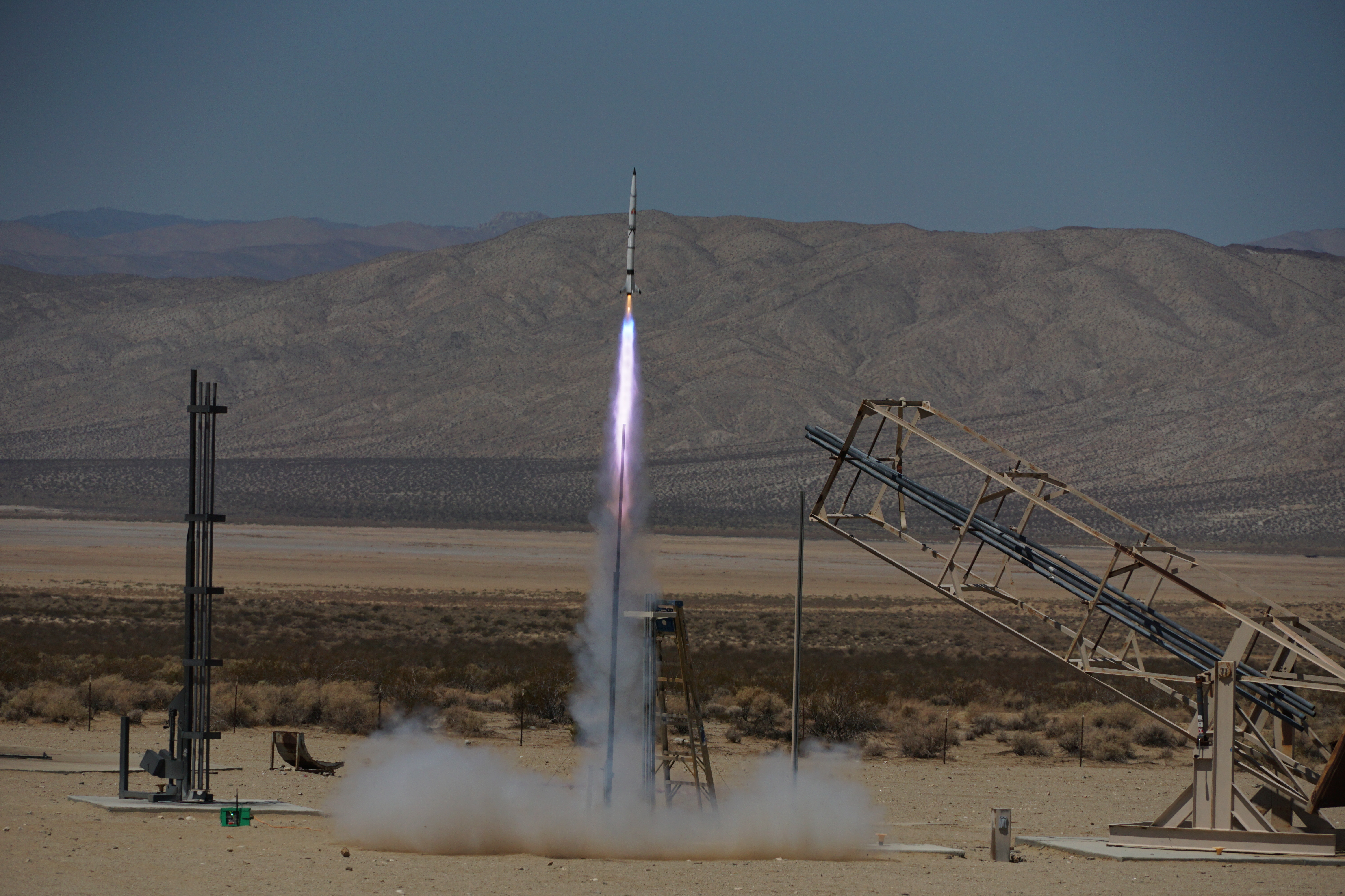
This is Tritium 2.2, a 65mm (~2.55 in) diameter fully printed rocket I've been working on for the last month or so. It's flying on a K2050 from the Friends of Amateur Rocketry launch site in Mojave hopefully as soon as this weekend. OpenRocket says I'll hit about Mach 1.75 on this flight (590 m/s, 1320 mph) and an altitude of 9500 ft / 2.9 km.
Tritium 2.2 (v16~recovered).png

The rocket's printed from primarily standard PETG on my (upgraded) Ender 3. The fin can is printed using a mix of carbon fiber/PETG blend filament for extra tensile strength as well as the standard white PETG. I'm using 5 fins with extremely wide fillets and diamond-shaped airfoils. I'm retaining the motor with a combination of a friction fit (this rocket uses a standard 54mm LOC motor mount tube, epoxied in) as well as head-end retention with a 5/16-18 eyebolt attached directly to the motor through a printed bulkhead and using the threaded plugged closure. The fin can and the first printed segment are epoxied together using RocketPoxy, while the second (blue) segment is held in using five #4 screws. The nosecone is a 7:1 VK printed in three parts—the first two are also epoxied together, while the tip is held in place using the eyebolt on the other side and a threaded insert embedded in the tip.

For recovery, I'm using drogueless head-end dual deploy. The "drogue" is about 12 feet of 1500-pound Kevlar cord, and the main is a 36" Apogee parachute. Motor-attached eyebolt aside, I'm using 1/4-20 hardware wherever possible, which while likely overkill for this rocket, is good practice for my future plans.

Avionics - Front.jpg

As far as avionics, I've got a Featherweight GPS for tracking, and originally planned to use a Raven 1 for primary deployments and Eggtimer Classic as backup. The Raven 1, however, refused to recognize any continuity after being installed. I'm replacing it with an EasyMini, and trying to see if I can keep the Raven as a datalogger. The avionics bay itself is printed with orange PETG and reinforced with two steel #6-32 threaded rods. The eyebolts attached to the avbay are both 1/4-20.

On that note, the Raven was the first of many hiccups with this build. Originally, I had planned to have the bottom end of the "drogue" shock cord attach to the printed body itself, as I was using the open floating forward closure. This worked relatively OK, but I was worried about a failure mode in which if that print tore, the entire fin can, casing and all, would tear off and fall on its own. Last weekend, after the third attempt that day to make it to the pad (first time, range closed before I was ready, 2nd time, installed a charge on the wrong computer), I dropped the nose of the rocket about 3 inches, and the print snapped right where that failure mode I expected would've been. Not great.

That brings me to today. After that attempt, I bought the threaded forward closure and worked to redesign the rocket to the current configuration, in which no printed parts should be under significant tension. It should be noted that printed parts can obviously handle some tension, however, if there's a defect in the part like the first attempt, that can cause an abrupt failure. I'm also adding the EasyMini, since @Neutron95 and I both felt pretty nervous about having an untested Eggtimer Classic handle deployments, and taking the motor apart to glue the grains just to be extra safe. I'll also likely look at making the rocket perhaps a bit prettier, since it's mostly unfinished right now and the FAR dust has left it looking pretty dirty.

The next flight attempt for this, again, should be as soon as 5 days from now (this Saturday) at FAR. I'll post about any progress from here, and glad to answer any questions folks have.
 

Attachments

  • Avionics - Rear.jpg
    Avionics - Rear.jpg
    1.5 MB · Views: 0
  • Exploded view.jpg
    Exploded view.jpg
    2 MB · Views: 0
Working on the extra piece to attach the EasyMini. Pretty simple piece, using the pre-existing mounts for the Eggtimer Classic as well as some zip-ties near the front and pressure against the Raven. Not the prettiest solution, but should work, and small enough that I can do a couple iterations. Vertical clearance is also well within requirement, so no big deal. I'm using almost pencil-like 1s LiPos on this, so shouldn't be very difficult to find somewhere to stick another battery.
1660551695690.png1660551749880.png
 
Well that was fast. Didn't realize how small this piece is, to be honest. 22 minutes. Fits pretty well, it's a little flimsy, but I don't have the actual altimeter to test with (and won't have it until launch day). I'm sure I can refine this a bit, but for now, I need sleep.

1660555040826.png1660555147175.png
 
Nice! Which brand PET+CF are you using?

And I assume the nose tip is also out of PET? I've found that my printed PET nosetips go from returning pristine on 29mm flights to ~mach 1.25 to shredded one use items on larger 38mm loads. Your flight profile is somewhere in between my datapoints, so curious to see how yours returns.

I've been playing with 3d printed molds for casting tips, but haven't gotten something I'm happy with yet.
Using this stuff: https://www.3dxtech.com/product/carbonx-petg-cf/. And yes, the nose tip is also made from the CF PET (mainly for looks, honestly.)

I've noticed that while the heat deflection temperature listed is the same as standard PETG (~85 C), the +CF filament still seems to retain its shape better under heat. Also this rocket should only be at high speed for a relatively short time thanks to the K2050's ridiculous thrust curve. However I'm possibly being talked into flying this on a K1103 at BALLS, if this works and I decide to go. That should put it through a bit more.
 
Also, quick update. Glued the grains of the K2050 yesterday to be safe. The motor doesn't explicitly call for grain gluing, but at high g, I might as well.

1660900851459.png


Today I've been working on just some minor touchups. The rocket's mostly ready for flight. I'll have to integrate the EasyMini on site, so really all I can do at this point is make sure all the batteries are charged and good to go. I painted the nosecone today with just some standard white enamel spray paint and sanded that down until it was decently even. I don't paint my rockets much, I usually leave them as bare plastic and add vinyl decals, but decided it'd be worth a shot this time.

Speaking of vinyl decals. I'm going with some Redstone-inspired graphics on here. I'm about halfway certain on painting a couple of the fins to have a mix between black and white, but with 5 fins, it's a bit troublesome to find a satisfying combo.

1660901092527.png1660901200924.png

All in all though, feeling pretty good about launch tomorrow. FAR's schedule looks absolutely packed, this might be one of the least interesting rockets on the pad, funny enough. ERAU's attempting a N5800-M1378 space shot and Evolution Aerospace are static firing three Q motors. Definitely makes me feel a little inadequate, haha.
 
Two questions -
1) What's the empty weight of your rocket?
2) What wall thickness did you use for the printed body tubes?
 
Two questions -
1) What's the empty weight of your rocket?
2) What wall thickness did you use for the printed body tubes?
1) Just about 1410 grams / 3.1 lb. Actually ended up decently overweight compared to what I originally planned, but that's due to beefing up the recovery system on this as much as I feasibly could.
2) The thinnest walls on here are 1.75 mm. I've printed tubes as thin as 0.6mm (with stiffening ribs) that have survived HPR flights, but not taking many chances on here.
 
The fin can is going to create some extremely interesting base drag as well as shock front interactions.

Looking forward to see the outcome as well as the accelerometer data from the Raven. It should be very interesting data. Would be even better if there was a 3-axis mems onboard as I think there will be some very interesting lateral data.
 
It flew! Then it very abruptly didn't.

1661041932861.pngView attachment 1661041958100.png

About 300 ms into flight, there was some sort of anomaly with the motor. I'm not sure what, gluing the grains should've prevented anything screwy, but some video my dad got (will post when I can) shows a pretty clear off-colored puff in the plume immediately before things went south. Worse, the Raven didn't record anything of use and the Eggtimer Classic's data is (expectedly) a mess. Silver lining: All the expensive bits came back in one piece, some of them very confusingly so.

This is how I found the fin can about 400 feet from the pad. Yes, all of that white stuff was once part of the rocket. What was left of the segment above was turned into literal confetti. It was a sight to behold, but not nearly as much of a sight as the aft closure.
View attachment IMG_9121.jpg

For something I can't imagine many of you have ever seen before: That's the eyebolt of the avionics bay lodged inside of the nozzle. I could not get it out without disassembling the motor. How this happens... is very beyond me. The aft closure took quite a beating but is still intact.
IMG_8067.jpg


Now for some failure analysis. As I said earlier, there was some kind of anomaly with the motor - while not an outright CATO, it definitely surged at one point. Without proper accelerometer data it's hard to make any conclusions, but the folks at FAR who saw the flight have a few theories for some possible causes.

First, the rocket had been on the pad for a solid 2 hours. The fun thing about FAR is due to low launch volume, and practically every launch being special in some way, there's sometimes pretty long wait times. I had to work around a 3-stage rocket on the adjacent pad and a team preparing a liquid rocket for a static fire about 100 feet away, meaning the rocket waited and waited. We had 3 launch attempts due to some issues with the igniter boxes, and each attempt required calling the entire site into bunkers due to the 3-stage and liquids team. Definitely not your normal launch flow. Add that with 110+ degree temperatures, and the motor had been cooking for a while.

Second, there were a few things I noticed I could have personally done better. The avionics bay still had some plastic acting as load bearing under tension, which is why the eyebolts immediately tore out. In the future, if I keep doing av-bays like this, I'm likely going to add metal bulkheads to interface with the threaded rods and eyebolts. It's overkill, but arguably way better than plastic.

Third, I could've definitely printed my parts with some thicker infill. I'm reluctant to add too much mass, this rocket already came in way overweight, but a heavy rocket is better than a rocket that doesn't make it.

All in all, well, when you go searching for the limit, occasionally you find said limit. I don't want to say a printed rocket on a K2050 is impossible, but it's going to take more work than this. All of the expensive bits came back, so if I do decide to re-attempt this in the future, I haven't lost much. But for now, I think I'm going to set my sights back on 38mm for a while and do a bit of smaller-scale testing before returning to this.

If I get any more data or pictures I'll post them here, but that more or less wraps this up for me. Again big thanks to @Neutron95 for supplying a ton of the hardware for this flight. Glad I could get it all back to you in one piece, even if the rocket didn't. Until next time.
 
My .02.... 3D printed parts got nice and hot, took off like a scalded cat, folded (shredded), hence why the avionics bay pieces had an opportunity to connect with the nozzle/aft closure.

Post the video of the motor burn please. :)
 
My .02.... 3D printed parts got nice and hot, took off like a scalded cat, folded (shredded), hence why the avionics bay pieces had an opportunity to connect with the nozzle/aft closure.

Post the video of the motor burn please. :)
Still waiting for the video to be sent to me, but I should note I'm using PETG which should be good to 175 F before any deformation under load. I'm not certain heat was much of a factor on the rocket structurally.
 
That's my thought too rocketkyle, you can see where the I bolt impacted the forward closure, looks like it swung around during RUD and wedged itself in there.

It'd be kinda nice if you had video, I had a K2050 do weird stuff on me but I though I just misassembled the motor. casing and everything was fine but it pressurized the airframe through the forward closure (regular floating closure, but no ejection charge). I could see both ejection charges go after separation so the motor must have separated the rocket. I use a plugged closure now with basically all my 54's.
 
Photo I got of the boost.
DSC07047.JPG
 
K2050's must use the forward seal disk with the o ring installed in the groove. They do NOT require grain bonding. Might I guess that you maybe got glue where it was not suppose to be and compromised an o ring seal?
 
K2050's must use the forward seal disk with the o ring installed in the groove. They do NOT require grain bonding. Might I guess that you maybe got glue where it was not suppose to be and compromised an o ring seal?
I was thinking something similar.

If the instructions do not tell you to bond the grains, I would not do so. The K2050 is probably designed as a BATES grain configuration. The ends of each grain are supposed to burn, as well as the core. Reason behind it is to maintain a nearly-constant chamber pressure. When you bonded the grains, you turned it into a straight core burner, which is a progressive thrust profile. The longer the burn, the higher the propellant surface area, the higher the chamber pressure.

DISCLAIMER: I have not profiled the K2050 with any sort of motor simulation software to see if the above statements are accurate. It is simply a SWAG.
 
I have flown many K2050 ST in an all 3D printed 1/52nd Saturn V. Never Have I bonded the grains. Motor burn has been perfect. KNOCK ON WOOD :)
 
I was thinking something similar.

If the instructions do not tell you to bond the grains, I would not do so. The K2050 is probably designed as a BATES grain configuration. The ends of each grain are supposed to burn, as well as the core. Reason behind it is to maintain a nearly-constant chamber pressure. When you bonded the grains, you turned it into a straight core burner, which is a progressive thrust profile. The longer the burn, the higher the propellant surface area, the higher the chamber pressure.

DISCLAIMER: I have not profiled the K2050 with any sort of motor simulation software to see if the above statements are accurate. It is simply a SWAG.
Grain bonding in this case probably means bonding the grains to the liner to prevent them from collapsing, not bonding the grain ends together.
 
I've never bonded the grains on a K2050ST.

That being said, the acceleration has been hard enough to rip the 3d printed tracker pod (hanging off of the aft eyebolt for the av bay) off of the av bay, and slam it into the motor resulting in a lost signal. Found it later that night with pure luck picking up the signal as I drove by. I've also broken another pod using the same motor.

Something to consider... People underestimate the power of the K2050ST.
 
Grain bonding in this case probably means bonding the grains to the liner to prevent them from collapsing, not bonding the grain ends together.
Okay, point taken. From the description of the failure, it sounded an awful lot like grain faces were inhibited, which could lead to the overpressurization I described.

As @mrwalsh85 mentioned, others have not had to bond grains on the K2050ST, so I found it curious that a failure was seen when the grains were bonded. Correlation? Yes. Causation? Maybe, maybe not.
 
Lavie,

The first 300ms looked good!

We learn 10X more from the fails on the range than the successes, because of all the post flight analysis.

Below are some screen grabs from video I captured and showed you in the office yesterday (while enjoying a moment of A/C). There definitely was a choke point in the burn at the instant parts started coming off. The overpressurization caused by the choke wasn’t too bad, but combined with the insane gees from that motor the release of pressure might have doubled the gees for a few milliseconds.

It appears that you lost your nose or part of the nose first and then it went into a death spiral. Since you found fins 1&2 attached and fin 3 within a few feet of the fin can, I suspect your fins performed well especially under the circumstances. Fin 3 likely detached on impact. It is tough to say if the burn anomaly caused the nose to fail and/or it might have failed given the force of that motor. Or the extreme heat on the pad might have weakened the 3D printed structures.

As mentioned yesterday, I’d recommend glassing the 3D printed airframe with epoxy and reinforce any high stress areas like AvBay bulkheads with more metal for a high gee flights. I’d guess you were very very close to having a successful flight but something up front gave out under maxQ — and maxQ was likely ‘super MaxQ’ due to the pop in the burn.

Mike


4A3B7047-0AE9-4234-8EA4-1CB2D8CEAFE8.png

BD0F529F-C15E-4C15-8D19-00A5B84576B2.png

77D680A1-0759-4C59-BD84-A671EBF85EC5.png
 
People enjoy using the term "max Q" a lot I have noticed. Hard to say that unless you know where "max Q" exists for that airframe profile, on that day, with the 3D print baking in the Mojave sun, and the air density, and the motors thrust profile being modified by the heat soak of the motor in the sun, etc.

As well, all the data was trash on the Raven (as per the OP), so you have no accelerometer data, so you have no data to validate anything related to structural loading and thus, Q.

So how/why did anything happen at "max Q" again??
 
So how/why did anything happen at "max Q" again??
It was not meant to be a literal reference. In general, the point of maximum dynamic pressure in my flights is at the end of motor burnout or when breaking through Mach. Lavie’s flight broke up toward the end of motor burn out, so likely around the time of maximum forces on the airframe. It didn’t happen at apogee or right on the pad — A lot of airframes and fins lose it towards the end of motor burn-out in HPR.
 
I was thinking something similar.

If the instructions do not tell you to bond the grains, I would not do so. The K2050 is probably designed as a BATES grain configuration. The ends of each grain are supposed to burn, as well as the core. Reason behind it is to maintain a nearly-constant chamber pressure. When you bonded the grains, you turned it into a straight core burner, which is a progressive thrust profile. The longer the burn, the higher the propellant surface area, the higher the chamber pressure.

DISCLAIMER: I have not profiled the K2050 with any sort of motor simulation software to see if the above statements are accurate. It is simply a SWAG.
Grain bonding in this case probably means bonding the grains to the liner to prevent them from collapsing, not bonding the grain ends together.

Okay, point taken. From the description of the failure, it sounded an awful lot like grain faces were inhibited, which could lead to the overpressurization I described.

As @mrwalsh85 mentioned, others have not had to bond grains on the K2050ST, so I found it curious that a failure was seen when the grains were bonded. Correlation? Yes. Causation? Maybe, maybe not.


So in this case, I bound the grains to the liner, not to each other. I didn't receive any grain spacer O-rings, however, @AeroTech does not have a drawing of the K2050 for me to confirm this. The thrust curve does point to it likely being a BATES configuration, but a profile like that could be explained by permissible levels of erosive burning and throat erosion, which are likely not negligible with a motor this powerful.

Included is a drawing of the K1103, which is more or less how I flew this motor. This is my first time building a K1103, however, @Neutron95 has said he hasn't ever gotten a K2050 with grain spacers either. Our reasoning for bonding the grains to the liner here was to prevent a possible grain collapse under high G, but that doesn't look like it helped at all.
1661143958998.png


Lavie,

The first 300ms looked good!

We learn 10X more from the fails on the range than the successes, because of all the post flight analysis.

Below are some screen grabs from video I captured and showed you in the office yesterday (while enjoying a moment of A/C). There definitely was a choke point in the burn at the instant parts started coming off. The overpressurization caused by the choke wasn’t too bad, but combined with the insane gees from that motor the release of pressure might have doubled the gees for a few milliseconds.

...


View attachment 533521

Thanks for the video screengrabs. 300 ms puts the point of failure at 225 (±50) m/s, 88 (±2) g, and 100 (±25) ft, so not past the sound barrier. I'm pretty sure that a surge in power like you described could have very well been the cause, as a doubling in G force could have shocked the rocket into failure. Wish I had the acceleration data to know for sure.
 
People enjoy using the term "max Q" a lot I have noticed. Hard to say that unless you know where "max Q" exists for that airframe profile, on that day, with the 3D print baking in the Mojave sun, and the air density, and the motors thrust profile being modified by the heat soak of the motor in the sun, etc.

As well, all the data was trash on the Raven (as per the OP), so you have no accelerometer data, so you have no data to validate anything related to structural loading and thus, Q.

So how/why did anything happen at "max Q" again??

It was not meant to be a literal reference. In general, the point of maximum dynamic pressure in my flights is at the end of motor burnout or when breaking through Mach. Lavie’s flight broke up toward the end of motor burn out, so likely around the time of maximum forces on the airframe. It didn’t happen at apogee or right on the pad — A lot of airframes and fins lose it towards the end of motor burn-out in HPR.

Well, here's where the rocket failed, based on that 300 ms estimate. Though quite honestly I'm looking back at my father's flight of the video and I'm thinking late end of the burn might actually be more accurate. Max Q? Well, technically, if a rocket has an aerodynamic breakup, it's likely maximum aerodynamic pressure by definition. But pedants will be pedants.

Will be uploading that in a second. It unfortunately doesn't show the anomaly, only liftoff and the aftermath.
1661145940560.png
 
Well here's the video from my dad.
Can't tell based on the video itself when the failure happens, but there's a loud pop about 530 ms into the burn (looking at the waveform in my editor). Which would actually put the upper bound of failure (green) at 420 ± 20 m/s (Mach 1.22), around 79 g, and an altitude of 340 ± 35 ft. I do think that altitude sounds a little bit more realistic.
1661147524630.png
View attachment Lavie - K2050.mp4
 
Back
Top