Building the Estes Little Joe II: Tips, Tricks, and Modifications

The Rocketry Forum

Help Support The Rocketry Forum:

This site may earn a commission from merchant affiliate links, including eBay, Amazon, and others.
After opening this thread some 20 months ago, I finally got around to adding the last final little detail to my Little Joe II model. Not long after the model was released, a modeler named Daniel Cavender posted a photo of a display stand for the model that he laser cut from plywood. I thought Daniel's stand was fantastic, so I reached out to him to see if he would share the file so I could cut one for myself. After cutting a kit over a year ago I get distracted by other projects, and the parts started gathering dust.

A few weeks ago I decided to dust them off and put the kit together. Daniel's engineering was fantastic, and the plywood bits fit together exceptionally well. Construction took just a bit of epoxy, and after some quick sanding the structure was hit with some primer, some gloss white, and finally some bright yellow (all Rustoleum).

While the stand isn't strictly scale, it is a great complement to the finished model. Thanks to Daniel for sharing the digital file for the stand, and thanks again to John Boren and Estes for modernizing and revitalizing one of the greatest kits in the history of our hobby!

James

View attachment 329347

PM me with your email address, I talked to my friend at work and is going to look into what he might charge for cutting these. He added some tweaks like "tab and slot" for the cross pieces. He is going to test some other materials as the luan plywood he used for mine charred pretty badly and some of the center plys fell out. This added some more filling work to finish the edges, but the thing fits together really well...you almost don't need any glue! Once he gets things worked out, I can forward your email to him and let you all work out details ;) He is pretty busy at his day job and has some other things going on, so I don't imagine he would be building a bunch of these in production...

If you can get someone to laser cut I would love to buy set.

Seconded! As a new member to the forum, this thread and the insights/information contained in it are outstanding.

I would also be interested in the LJII wooden stand if someone is able to print and sell.

-Mike

If no progress on the stand yet, I contacted a small laser shop in San Diego (FLB Laser), and for a quantity of 6 or more, it would be $50 per stand, including materials (premium 1/4" Baltic Birch ply), sanding and cleaning of the finished cut pieces. Shipping and handling would be extra of course. But this may be a way to go forward on this. My question is, would this be an improper use of Daniel's file, if these stands are sold at cost?
 
I forwarded email addresses of folks who expressed interest in the stand to my friend at work that cut mine for me. He was going to experiment with different materials to see which would provide the best cut (the Luan he used for mine charred quite a bit, and some of the inner plies chipped out on the tiny crossbeams). He has been slammed at work with a hot project, and had some other laser home projects that had priority. He was going to get back on these, and is trying to figure out how to setup a payment system. I have been on vacation, and will check on progress this week.

Meanwhile, I am posting the FB link to the original file, as I'm not comfortable re-posting the file itself here without the creator's permission... https://www.facebook.com/groups/2255560886/permalink/10154885315670887/
 
I built my kit stock with all of the helpful hints here, and it will fly this coming Saturday for the 50th Anniversary Apollo 11 launch...
I'm planning on using a D-12-3 for a sort 300ft hop, where should the balance point be? My model weighs in at 7.60oz empty and 9.20oz with the motor....
I used the 2 1/2 pats of clay in the nose tube, and the other 2 1/2 pats in the nosecone itself...
Any suggestions would be appreciated!

Read this thread to estimate it...https://www.rocketryforum.com/threads/cg-center-of-gravity.10546/

My Rocksim places the CP at 16.7 inches from the top of the escape tower. A rocket width of 2.5 inches places the CG at about 14" from the top. That said, my rocket may be simming out differently because I overbuild the fin can and thus added BB's and epoxy to the escape tower vs. the clay pats (so mine is heavier). If you follow the instructions in the thread above you should be able to determine the CP and CG for your build. The only issue in figuring it out m=now is that if it's unstable, where do you add more weight?
 
I built my kit stock with all of the helpful hints here, and it will fly this coming Saturday for the 50th Anniversary Apollo 11 launch...
I'm planning on using a D-12-3 for a sort 300ft hop, where should the balance point be? My model weighs in at 7.60oz empty and 9.20oz with the motor....
I used the 2 1/2 pats of clay in the nose tube, and the other 2 1/2 pats in the nosecone itself...
Any suggestions would be appreciated!
The instructions clearly state where the balance point should be. Load it up like it will actually fly (motor, wadding, recovery, etc.) and check your balance point.
 

Attachments

  • EstesAPLJII_7227.JPG
    EstesAPLJII_7227.JPG
    109.7 KB · Views: 94
The instructions clearly state where the balance point should be. Load it up like it will actually fly (motor, wadding, recovery, etc.) and check your balance point.

That's interesting, my instruction sheet doesn't have that diagram that you posted....Hmmm, I wonder why?
Thanks for posting your copy though!
 
That's interesting, my instruction sheet doesn't have that diagram that you posted....Hmmm, I wonder why?
Thanks for posting your copy though!
Ah Ha! Found it! Very sneaky! It's an extra page, not folded together with the rest of the instructions!

Thanks again for pointing this out!
 
Ah Ha! Found it! Very sneaky! It's an extra page, not folded together with the rest of the instructions!

Thanks again for pointing this out!
The printed set that came with my kit were in German!!! I had to download the English version from the Estes website :D
 
The printed set that came with my kit were in German!!! I had to download the English version from the Estes website :D
Instructions in most Estes kits now come in multiple languages. There should be an English/Spanish/French set in your kit in addition to the German/Italian(?) set. I usually cut out any templates, guides, and shock cord anchors from the set I'm not going to use before discarding it, so as to keep my English instruction set in one piece. (And to have backup template copies).
 
Talk about a treasure trove of good info. Glad I read this. I have pulled my LJ2 kit out of storage and will probably start work on it this week. There are some things I will be doing with this bird that might be slightly different from the norm.

1. Wrap adhesive- I had very good luck using Bob Smith Industries Finish Cure epoxy to glue the wraps on my Estes #1969 Saturn V, so I will be using that for my build instead of spray adhesive. I believe it may result in stronger bonds around the fin root stems and its more viscous (yet thinner than regular epoxy glues) surface tension should provide more bonding strength surface area.

2. Plastruct Plastic weld for exterior bonding- Yes, the orange glue from Plastruct is the best stuff to use. Ambroid Proweld may also work, although it might be a little too hot for styrene parts while Plastic Weld has just the right amount of bonding strength without melting bits into goo.

3. Tamiya/Aizu tape for small details- The wraps done look great, but I like surface relief. My Saturn made very good use of thin tape strip for details on the 1/100 CSM, so I will be doing something similar on the CSM of the LJ2 for my CSM-002 representation.

4. Plastic detailing added to the BPC and LES- Evergreen and Plastruct strip styrene worked wonders on the BPC of my Saturn, so I will be doing similar work on my LJ2 capsule. I know, Shapeways has a capsule I can print, but I like old school hand detailing to get the BPC looking right.

5. I may use Alclad to do the silver, but Tamiya spray will be my backup as it is very durable paint with an excellent finish.
 
I forwarded email addresses of folks who expressed interest in the stand to my friend at work that cut mine for me. He was going to experiment with different materials to see which would provide the best cut (the Luan he used for mine charred quite a bit, and some of the inner plies chipped out on the tiny crossbeams). He has been slammed at work with a hot project, and had some other laser home projects that had priority. He was going to get back on these, and is trying to figure out how to setup a payment system. I have been on vacation, and will check on progress this week.

Meanwhile, I am posting the FB link to the original file, as I'm not comfortable re-posting the file itself here without the creator's permission... https://www.facebook.com/groups/2255560886/permalink/10154885315670887/
I know, it's weird replying to my own thread, but I wanted to provide an update...my friend James is now ready to cut display stands. From his email:
The cost for Little Joe II stand is $30 via paypal
I am using .210 thick birch plywood. It is stable with little to no warping. So far, I have found no voids in the plywood.
For inquiries, contact James at:
ZStraightline101Z at gmail.com
(note remove the Z's and change the at to @ to get his correct email address
 
I highly recommend using the through the wall technique to mount the fins. I've flown mine 4 times and have not lost or even cracked a fin.
 
That's an interesting thread. I have a 1:25 scale LJ 2 project "idling" and CP location is one of the themes that I am not yet 100% sure about.
It is common knowledge, that CG should be about one caliber ahead of CP.
But there is also "what Barrowman left out": https://argoshpr.ch/joomla1/articles/pdf/sentinel39-galejs.pdf According to this (and I know it is correct), about half a caliber may be good enough.
Accurately modeling the escape tower and its skirt is not neglectable as well.
So I am more or less settled to build a small test rocket on a B motor and to play with the CG location until stability gets marginal.
I shall post the results here if I don't forget ;)
Meanwhile I wonder what CG other LJ 2 builders are using with success?
 
Fat stubby rockets can get away with < 1 caliber of separation. I've taken this to be because of base drag.

1 Caliber is an easy-to-remember rule, But also a bit of a blunt instrument that doesn't take account of everything. But just try and get less than 1 past your RSO...

I've created 3D printed jigs for building the LES tower on the SEMROC LJ II, and they really helped. Will have them up on YouMagine within a few days. Might be helpful to scale up, or point the way to your own design.
 
That's an interesting thread. I have a 1:25 scale LJ 2 project "idling" and CP location is one of the themes that I am not yet 100% sure about.
It is common knowledge, that CG should be about one caliber ahead of CP.
But there is also "what Barrowman left out": https://argoshpr.ch/joomla1/articles/pdf/sentinel39-galejs.pdf According to this (and I know it is correct), about half a caliber may be good enough.
Accurately modeling the escape tower and its skirt is not neglectable as well.
So I am more or less settled to build a small test rocket on a B motor and to play with the CG location until stability gets marginal.
I shall post the results here if I don't forget ;)
Meanwhile I wonder what CG other LJ 2 builders are using with success?
 
I wouldn't worry about modeling the escape tower. Just build it, weigh it, measure the length, find its CG and enter the values into Rocksim. Don't glue the ecsape tower tube to the transition until last. Finish the model, find the CG and CP, model the weight to add to the escape tower until you get 1 caliber and then add the weight to the tower - clay or BB's and epoxy. I added mine first based on some calculations and entered too much weight. lesson learned, adding weight is the very last step in the build.
 
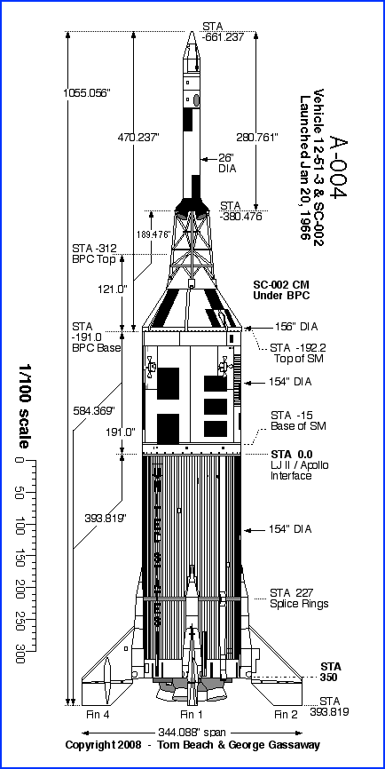
The known-to-be-stable CG location for the Little Joe-II is at, or above, the "N", in UNITED STATES (if the lettering is applied in the proper location). Couple of models I had where the CG was below the N, sometimes went unstable. AT the N or higher, always stable. If you cluster.....make it more nose heavy.

Sim software does not handle very well the complex aerodynamics of a tower-type escape motor and flared-out skirt.

I keep forgetting to modify an old drawing to show where the stable CG is, based on dimensions, rather than the "N".

NOTE - the models I learned this with were ones like A-003 and A-004, with the long Fin Root Fairings, which QTV and A-001 did not have (and A-002 had short fairings).

A-004.gif
 
Last edited:
Cool, thanks for that feedback.
Mike, I have my doubt that the escape tower can be ignored, but modelling it is tricky, as outlined by this: https://apogeerockets.com/education/downloads/Newsletter238.pdf
George, thanks, I'll depart from that.
The ESTES CG (rocketguy101 post) is even a bit less conservative, it seems.
I intend to build A004, igniting 2 x H128 on the ground and airstarting another pair later, to mimick the original. So yes, I need more stability.
Possibly I'll aim at having CG somewhere at STA 0, while pointing the centerline of all motors to the halfway point between CG and CP.
What still leaves the question where that CP is actually ;)

Maybe I have to dig out that old "windtunnel" we used for the Arianne ;) https://www.argoshpr.ch/archiv/Ariane010527/Ariane010521_09.jpg
 
Last edited:
Btw, on "canting clustered motors", here is a little test I did, using only one (!) outboard motor, aimed at midpoint between CP and CG...
Proof of concept, I'd say.
https://argoshpr.ch/piwigo/_data/i/upload/2018/08/06/20180806191848-89c755ed-me.jpg
https://argoshpr.ch/piwigo/_data/i/upload/2018/08/06/20180806191852-3c975943-me.jpg
https://argoshpr.ch/piwigo/_data/i/upload/2018/08/06/20180806191854-55c012dc-me.jpg

(It's not my idea, I took that from an old HPR mag article, but am working on the theme, to document it more)
 
Hello! This is a wonderful thread with lots of information on building the Little Joe II. I just about finished mine (see attached pictures). The only thing I had left to do was glue on one of the four little sets of direction rockets. It was the only thing left because I had to make a small repair on it. Two of my cats have pica syndrome. I left it on my bar overnight, and one of my cats ate it. I noticed that some people on this forum purchased multiple boxes of this model so they can test build as they work on their main model. Does anyone have the five small pieces spare to build the direction rockets that I can purchase? There is a picture of them assembled attached. Thanks!
 

Attachments

  • 20220211_075746.jpg
    20220211_075746.jpg
    135.9 KB · Views: 21
  • 20220211_075802.jpg
    20220211_075802.jpg
    99.1 KB · Views: 20
Hello! This is a wonderful thread with lots of information on building the Little Joe II. I just about finished mine (see attached pictures). The only thing I had left to do was glue on one of the four little sets of direction rockets. It was the only thing left because I had to make a small repair on it. Two of my cats have pica syndrome. I left it on my bar overnight, and one of my cats ate it. I noticed that some people on this forum purchased multiple boxes of this model so they can test build as they work on their main model. Does anyone have the five small pieces spare to build the direction rockets that I can purchase? There is a picture of them assembled attached. Thanks!

I learned that they are called the reaction control system. I found somebody on ShapeWays to 3D print some for me.
 
Here's the video of the vNARCON LJII build, which is essentially a duplicate of the build done for this thread many years ago.


...and here is the finished model, complete with display stand. (Please ignore the forest of Frank Burke-designed gliders in the background.)

IMG_6909.jpeg

James
 

Latest posts

Back
Top