Questions about my DIY Launch Controller

The Rocketry Forum

Help Support The Rocketry Forum:

This site may earn a commission from merchant affiliate links, including eBay, Amazon, and others.
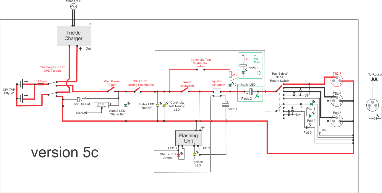
The 1st one is it! No, you won't fry the piezo. C? will work; B2 won't! No, C? won't short out the continuity test. Yes, you will get a light and beep. If you use B2, you will only get the forward voltage drop across the diode to power the piezo, and besides, it doesn't make sense to do it that way.

OK, maybe I'm not using the right words. C may not "short" the continuity test, per se, but getting a light and a beep w/o igniter continuity makes the test invalid and moot.

And version A just looks so incongruous.

A large portion of this thread is guys telling me to use the right (i.e. heavy 16 AWG) wire for this. Esp for the "high power" side of the circuit. The leads on this buzzer are like hair! If I have to place it in the middle of the high power circuit like that, I'm very tempted to cut open the plastic case on this thing and replace the leads w/ at least 22 AWG.

and aren't I getting a forward voltage drop to power the piezo, no matter what I do (A, B2, or C) ?

I love the Fawlty Towers dig! Classic!

I didn't mean it as a "dig" I just meant "Yes!, I know...."
 
OK, maybe I'm not using the right words. C may not "short" the continuity test, per se, but getting a light and a beep w/o igniter continuity makes the test invalid and moot.

And version A just looks so incongruous.

A large portion of this thread is guys telling me to use the right (i.e. heavy 16 AWG) wire for this. Esp for the "high power" side of the circuit. The leads on this buzzer are like hair! If I have to place it in the middle of the high power circuit like that, I'm very tempted to cut open the plastic case on this thing and replace the leads w/ at least 22 AWG.

and aren't I getting a forward voltage drop to power the piezo, no matter what I do (A, B2, or C) ?


I didn't mean it as a "dig" I just meant "Yes!, I know...."
Yes, you do use the heavier gauge wire for your ignition circuit, but the piezo doesn’t require the same high current to operate. It only uses a low current, hence the lighter gauge wire. It doesn’t matter that it’s connected across your high current circuit, it will still only draw what current it needs. So, you do not need to change the piezo leads.

In the B2 configuration of the piezo, the piezo will only have the forward voltage drop of the diode (typically approximately 0.7V, but depends on the type of diode) across the piezo when you press the continuity or ignition switches. You better google “forward voltage drop of diode” so that you understand what I’m saying here, and I’m not trying to be patronising either. This is not enough to operate the piezo - it probably requires 6 - 12V. This, of course, requires an igniter to be installed AND have continuity. Without an igniter you will not have a closed circuit, so no current will flow anyway.

With the C configuration, you are getting the full 12V across the piezo when you use the ignition switch, but I’m not certain what voltage will be across the piezo when you use the continuity switch, as it would depend on the input resistance to the piezo module, which would be in series with the continuity LED and 350 Ohm resistor. It will be less than 12V, though. I know that this configuration is not going to give you exactly what you want, but you are trying to do too much with a single piezo. You will have to increase the complexity of your circuit to achieve this.

You could place a piezo in parallel with the continuity LED and resistor, and another on the output side of the ignition switch and (-). If you do this, you will also need to instal an isolation diode between the output of the ignition switch and where the continuity LED connects to the ignition output line. However, this is, in my opinion becoming unnecessarily complex, but it might work for you. If I had more time I could probably think of something smarter, but it’s getting a bit late!
 
Yes, you do use the heavier gauge wire for your ignition circuit, but the piezo doesn’t require the same high current to operate. It only uses a low current....
I know that part
here:This is a better picture of what we're talking about.
LCS1Schem5c.png

A: we're going from 16 AWG wire down to pubic hair wire, through the buzzer, more thin wire then back to 16 gauge, and out to the launchpad. (?) It is a 3 to 24V DC piezo.

I'll do that if you say it's ok (although I'm not sure why, I haven't asked you for any credentials or anything :) ) It just that most of this thread is guys telling me not to do that.

Maybe just "D" is the answer. I put Piezo 2 on the continuity test only. I get a beep during the test; not during launch, but nothing is in the way of the high power circuit.

BTW: "unnecessarily complex" is (clearly) my middle name. please elaborate. And take your time.
 
Last edited:
I know that part
here:This is a better picture of what we're talking about.


https://benmargolis.com/LCS1Schem5c.png
LCS1Schem5c.png


[OK, MODS WHAT GIVES? THE PIC ABOVE IS BEING HOSTED ON MY OWN PERSONAL WEBSITE AND THE LINK WORKS. WHY DOESN'T IT SHOW UP HERE???]


A: we're going from 16 AWG wire down to pubic hair wire, through the buzzer, more thin wire then back to 16 gauge, and out to the launchpad. (?) It is a 3 to 24V DC piezo.

I'll do that if you say it's ok (although I'm not sure why, I haven't asked you for any credentials or anything :) ) It just that most of this thread is guys telling me not to do that.
LCS1Schem5c.png


Maybe just "D" is the answer. I put Piezo 2 on the continuity test only. I get a beep during the test; not during launch, but nothing is in the way of the high power circuit.

BTW: "unnecessarily complex" is (clearly) my middle name. please elaborate. And take your time.
No, no, no! You’re completely misunderstanding what I’m saying. That schematic above will not work! When I get some time I will draw up what I mean.

For the record, I am a retired electronics engineer, having worked for several decades in university R&D areas.
 
Thank you. For your work and for your patience. (yes, I can read that)

I'm just glad that I could tell that position A was wrong. See, I was paying attention.

I've just been reading about diodes at wiki for an hour. Jeese! I had no idea about reverse leakage current, much less voltage drop. (Boy a guy would need a degree in all that. :))

A THIRD piezo in this thing would be silly. (as if up till now, this hasn't been silly)

So I'll be using a Continuity piezo were you have it, or maybe where I have in D, depending on what that 350 ohm resistor does to the sound. I'm hoping it will go from being a loud, harsh, "TEEEEEET" to being a nice soft "BOOOOP" but i'll find out when the parts get here.

That was the last technical question. :D

I'm realizing that the actual building of the thing, mounting the batteries, drilling the holes in the control panel, that's going most of the job. Soldering all the connections is going to be light easy fun work by comparison.

Thanks again!
 
I put continuity piezoelectric beepers on all of my pad boxes but it was really a complete waste. Even with two continuity leds, the igniter, and a 420 ohm resistor in the continuity test loop the LEDs are very bright.

I would place the upper lead of the ignition buzzer between the arming switch and the ignition switch with the lower lead going to the other side as you already have it. Then it would buzz whenever you’re armed. The way you have it, it’ll only buzz when you push the launch button, and possibly not even then because it’ll only see the forward voltage of the steering diode..

Also, what’s the electrical requirement for the piezo buzzers you intend to use?
 
1. I have and "armed" beep. It actually goes TEEET TEEET TEEET like a truck backing up. And now I have a steady tone for Continuity as well :)

2. Why the beeping? Fair question. The kids usually are the one pressing the launch button. (that's why I'm making it so 'fun') And with beeping, I won't have to be looking over their shoulders to know whats going on. It will also get the spectators' attention (and get them to shut up) and lastly, it will remind the kid to turn off the system after launch.

Which brings us to what I believe is the final schematic.

N1PlZO6g.png


EDIT: oh and they are 12 volt piezos (rated 3 to 24 volts)
 
Last edited:
1. I have and "armed" beep. It actually goes TEEET TEEET TEEET like a truck backing up. And now I have a steady tone for Continuity as well :)

2. Why the beeping? Fair question. The kids usually are the one pressing the launch button. (that's why I'm making it so 'fun') And with beeping, I won't have to be looking over their shoulders to know whats going on. It will also get the spectator's attention (and get them to shut up) and lastly, it will remind the kid to turn off the system after launch.

Which brings us to what I believe is the final schematic.

N1PlZO6g.png


EDIT: oh and they are 12 volt piezos (rated 3 to 24 volts)

And what current do they draw?
 
Ooooh, My diodes have arrived! Now I can finally rectify things around here :D

10 mA (if I'm reading that correctly)
 
I put continuity piezoelectric beepers on all of my pad boxes but it was really a complete waste. Even with two continuity leds, the igniter, and a 420 ohm resistor in the continuity test loop the LEDs are very bright.

I would place the upper lead of the ignition buzzer between the arming switch and the ignition switch with the lower lead going to the other side as you already have it. Then it would buzz whenever you’re armed. The way you have it, it’ll only buzz when you push the launch button, and possibly not even then because it’ll only see the forward voltage of the steering diode..

Also, what’s the electrical requirement for the piezo buzzers you intend to use?
Yes, good suggestion. I don’t see the point of having an ignition beeper, either. I only use one beeper for arming on my pad boxes. Even continuity just uses an LED at the pad box and LC box. If you’re using the heavy duty beepers, then they might draw significantly more current than the smaller PCB style ones.

Yes, if there’s a dead short at the igniter, you will only get the diode voltage drop across the beeper. This is one of the issues I have with this circuit design philosophy. I use a relay-based pad box where I don’t have these issues. It’s also easier for continuity testing.

That is what I use too, relay pad boxes. I use silver satin (flat phone cord) as the connection cabling between the controller and the pad boxes. Everything is simple. It has to be for club launches. The system has lasted for 16 years now.
 
I built our 2 x 4-channel pad club system about 3-4 years ago and it has be a real workhorse since. I have recently retired the 9-core shielded field cable and built some RF modules that expand it to a 5 x 4-channel pad system. Because we now operate with up to 3 pads at distances out to 90 meters, we thought going wireless was a no-brainer. Our OP will probably realise down the track that a relay-based system is the way to do this. But, we all have to start somewhere and learn along the way.
 
I built our 2 x 4-channel pad club system about 3-4 years ago and it has be a real workhorse since. I have recently retired the 9-core shielded field cable and built some RF modules that expand it to a 5 x 4-channel pad system. Because we now operate with up to 3 pads at distances out to 90 meters, we thought going wireless was a no-brainer. Our OP will probably realise down the track that a relay-based system is the way to do this. But, we all have to start somewhere and learn along the way.

Nice!
 
Not wanting to hijack the thread, but as an example of what we've been using for our club DIY launch system, the pics below show 2 x 4-channel pad boxes and the 8-channel LC box. The schematic shows a 4-channel version of this system. It has been a very reliable system for us, except for the fact that I used DB9 connectors for the field cable connections. Not a good plan!
4 Channel Launch Controller.jpg
 

Attachments

  • LC.jpg
    LC.jpg
    248.6 KB · Views: 81
Last edited:
FWIW - a thread I posted about a controller i made a few years ago.

https://www.rocketryforum.com/threa...ds-clear-cliplite-holders-piezo-beeper.61764/

f1SIg0u.jpg


Video shows it being armed, and then the continuity lights and piezo beeper when the clips were connected (offscreen). I use piezo beepers for all launch controls. The beeper "beeps" due to a flashing LED inside the case, wired in series to the beeper.

The LED's are super-bright ones, water-clear, that glow red or green when lit. Clear bezels. Better than old style transparent red or green LED's since sunlight can fool you as to whether they are lit or not. With these, you only see a color if they are lit.


Also these days, my favorite launch battery is a 2000 mAh or so 11.1 volt LiPo battery. Relatively compact and packs a lot of punch. And I have them (and charger) anyway for R/C electric plane flying. Before that, I was using 4 to 5 Ah Gel Cells.
 
Sorry I am a bit late to the party on this thread, but here is a link to one I built a while back. Fairly low-tech but good features.
https://www.rocketryforum.com/threads/homebuilt-launcher-including-pics-schematic.108736/

Launch control 1.jpg

Some of the pics earlier in the thread have dropped off but the text is still good, and pictures towards the end.

I would probably use a LiPo pack these days, maybe add a built-in charger or something. I did build this 11 years ago so I might have learnt something along the way. I still use it :). Feel free to steal any ideas...

Share and Enjoy!
 
(isn't there already a "Show off your Launch Controller" thread?)

I just did a test. The piezo makes exactly the same noise with and without the 350 ohm resister in the circuit.

And looking at schematic 6 doesn't placing the piezo parallel to the continuity LED like that create a path around the 350 ohm resister? And wouldn't that let high power into the test?

shouldn't it be in series with the LED and the resistor?

If the buzzer only draws 10 mA, you can place it parallel to the continuity LED. It’ll simply add 10 mA to the current flowing through the igniter. Or you could use it in series with the resistor and LED, but it will only get a small voltage there, which could result in a weak buzzer and weakly lit LED. You may even be able to use it instead of the 350 ohm resistor. You can calculate the current that flows through the igniter or you could test it in these different positions to see what you like. Put an ammeter in place of the igniter and record what you see.
 
If the buzzer only draws 10 mA, you can place it parallel to the continuity LED. It’ll simply add 10 mA to the current flowing through the igniter. Or you could use it in series with the resistor and LED, but it will only get a small voltage there, which could result in a weak buzzer and weakly lit LED. You may even be able to use it instead of the 350 ohm resistor. You can calculate the current that flows through the igniter or you could test it in these different positions to see what you like. Put an ammeter in place of the igniter and record what you see.

1. I just put it in series w/ the resistor its a loud clear noise. (why do you say it will only get a small voltage there")

2. I'm sorry I guess I still just don't get electricity.
The buzzer consumes 10mA, so it's only going to add 10mA to the current going through the igniter. OKaaaay, but the ignition switch consumes zero electricity and its going to add ALL of the current to the igniter?? do you see my confusion here?

My (mis)understanding was that circuits like this were governed by how much power is available, and how much power the components pull. And if there are 20amps available and the igniter has a clear path to it (though the piezo) isn't the ignite just going to pull it though the piezo?
How current draw works is every component acts as a resistor. The piezo is around a 1.2kOhm resistor (12V / 0.01A) Just treat it like that.

Switches do not draw zero current. If you put a switch directly across the battery, it would draw hundreds of amps and melt everything concerned, basically acting as an electric heater. The only reason it doesn't is that the rest of the circuit (igniter, cables, etc.) limits the current to a few amps.
 
How current draw works is every component acts as a resistor. The piezo is around a 1.2kOhm resistor (12V / 0.01A) Just treat it like that.

I see, so when I have the piezo (which is a resister) and the resister and the ignitor (which is a resister) which I didn't do in my test, all in a line, THAT's when I'll have no power.

AAHH
 
I see, so when I have the piezo (which is a resister) and the resister and the ignitor (which is a resister) which I didn't do in my test, all in a line, THAT's when I'll have no power.

AAHH

Well, you also must look at the voltage drop through every component in a series circuit. So, if you place a 350 ohm resistor in series with a piezo buzzer, an LED, and an igniter, each component represents a voltage drop, proportional to the resistance of that component times the current flowing through the series circuit. LEDs also have a forward voltage which must be surpassed in order to get current to flow at all. When I asked for the specs for the buzzer, you gave one spec only, the optimal voltage. It’s crucial to know all of the specs, which could be numerous. Then, when I asked about current, you answered tentatively that it was 10 mA.
In general you add all the resistance in a series circuit then divide that into the voltage drop across the entire series circuit minus forward voltage of the LED, which in this case is probably around 0.7 volt. So, the voltage that drops through the circuit is probably about 11.3 volts, assuming 12 volts from the battery, which of course is incorrect, but okay for this example. So, divide 11.3 volts by the total resistance. That will give you the circuit current. Every component in a series circuit has the same current passing through it which is limited by the total resistance of the circuit.
Then you multiply the circuit current times the impedance, or resistance, of each component to find out the voltage drop for that component. The voltage drops will add up to the total voltage across the circuit.
So the reason I said the piezo buzzer and the LED might be muted (and the word might is important because I don’t know all of the specs about your buzzer or LEDs) is because the buzzer, which you told me is a 12 volt device might only see 9 volts, or 6 volts, depending on the calculations above and because if the buzzer limits the current to 10 mA, that might result in a dim LED.
 
Yes, but I think the folks here (myself included) were hoping to give you some examples of their design work to assist your endeavours. It’s not our intention to hikack your thread.

No prob.

Actually I'm surprised how much mine is going to going to look like yours. I'm using the orange version of that box.

I don't have access to that fancy circuit board printer, nice control panels.
 
I don't have access to that fancy circuit board printer, nice control panels.
Circuit boards are surprisingly easy to make if you want a relatively simple board with relatively large features.
Once you have your design planned and sketched out (probably on paper in this case):
  • Get some bare PCB material (start off with single sided ;))
  • Cut a piece the required size
  • Use steel wool to remove any oxide from the surface and clean it up
  • Draw the track pattern on the copper using a permanent marker (Artline, Pilot etc) or a paint marker, or one of the purpose-made markers if you are keen.
  • Once dry put the board in a tray of ferric chloride etchant to remove the unprotected copper. Keep gently swishing it till the exposed copper is gone.
  • Remove from FeCl3 and wash. (Note: FeCl3 stains clothing, skin and surfaces!)
  • Drill holes where needed. In your case you probably only need a 1mm bit for the smallest holes.

I would suggest etching a small test coupon first to check the marker works (so many different types).

It really is not that hard and the only things you are likely to need to buy are the F3Cl3 and bare PCB laminate. Give it a go and add another skill to your repetiore ;)
You can use ammonium persulphate as an etchant but you need to heat it so it is more nuisance value to use.

Don't forget space for mounting holes.


Thank you.
I'm certain you think that's "surprisingly easy" and that I should try it. But to a lot of us that reads like: "Its easy, just replicate some duranium, set your warp core manifold to 300,000 kelvins, then inverse the polarity of the main deflector ...." :)

For my attempt, I've already bought some clear lexan the right size. I'm planning inkjet printing the artwork on one sheet, and sandwiching that between the lexan and some (as yet still undermined) backing material. If this was the 20th century I'd be thinking thin plywood. Today, I'm wondering about 1/16" MDF board or something. At Home Depot they had masonite and stuff but that all seemed too heavy.

I'd like to see the inside of those boxes of yours actually.

How did you mount the panel to the pelican case? Did you buy the official pelican little pieces of plastic? Did you buy the official 3M $40 bottle of glue with the $9 applicator gun and the $3 single use nozzles?

I bought a square dowel that I'm fitting in the corners of the case with $4 loctite plastic glue that claims it will do the job. We'll see.

On another note. please explain grounding:
Grounding ("earthing") involves hammering a copper steak into the ground. I have to ground all the coax cable running around the outside of my house. That's not the same as V- out of a battery. (right?) On your schematics, is your system actually grounded? or is that just graphical shorthand for a common V-?
My panels were simply mounted on 10 mm Aluminium angle, as shown in the images below. There are small extrusions near the top of the inside of the case that the angle sits on. I just cut the appropriate lengths of Aluminium and glued them in place with 5 minute epoxy. I then drilled and secured them with self-tapping screws. Cheap, easy and solid.

Grounding is all done with reference to the battery negative (V-) as the common connection. All the earth or ground symbols on my schematic are referenced to the battery V-. It is an implied connection without drawing any wires.

All my circuit boards were bolted to the underside of the front panel. As you might see in the images below, the cases are bigger than the ones in the original images I posted. The larger cases were used so that I could include the 12V gel cell inside the case, rather than connecting externally, as they were originally. I can recharge them via the two 4mm banana connectors, or still use an external battery if required.
 

Attachments

  • IMG_20180714_232752 (2).jpg
    IMG_20180714_232752 (2).jpg
    113.6 KB · Views: 115
  • IMG_20180714_232814 (2).jpg
    IMG_20180714_232814 (2).jpg
    58.3 KB · Views: 113
  • IMG_20180714_232537 (2).jpg
    IMG_20180714_232537 (2).jpg
    160.4 KB · Views: 124
  • IMG_20180714_232416 (2).jpg
    IMG_20180714_232416 (2).jpg
    213.8 KB · Views: 121
  • IMG_20180714_232939 (2).jpg
    IMG_20180714_232939 (2).jpg
    162.3 KB · Views: 124
  • IMG_20180714_233148 (2).jpg
    IMG_20180714_233148 (2).jpg
    208.8 KB · Views: 102
I was joking with WarnerR about using my eGGtimer Quantum as a wireless launch controller - he quickly reminded me it has no physical key to lock and remove and no spring loaded fire button.

Perhaps I will test LPR at a non sanctioned class 1 launch

Kenny
 
Back
Top